A three-dimensional numerical model of a disk brake to study temperature on a discrete contact of rough surfaces has been developed. It includes the system of equations formulated based on thermotribological postulates of heat dynamics of friction and wear with mutual influence of contact pressure, velocity, properties of materials, and temperature. Two approaches of calculation of the flash temperature and its influence on the maximum temperature during a single braking application were studied. Changes in the contact temperature, sliding velocity, and the thermomechanical wear during braking were shown and discussed. It was found that two of the examined variants of calculation of the flash temperature agree well for the three considered materials of the brake pads combined with the cast iron disk, at each initial sliding velocity in the range from 5 to 20 m s−1.
Modeling of non-stationary processes of frictional heat generation with interdependent temperature, coefficient of friction, sliding velocity, contact pressure, and wear requires taking into account complex mathematical and physical aspects. Mechanisms of interactions between the operating parameters and the phenomenon of formation of a micro-contact on the friction surfaces were analyzed with reference to models of frictional heating proposed by Blok, Jaeger, Archard, and Kuhlmann-Wilsdorf in the review article.1 These solutions concern mainly specific geometrical objects, which are difficult to implement in real friction couples. The comprehensive research on thermal processes in brakes and clutches with the development of new materials and methods for their testing was carried out by Chichinadze and his co-workers. The experimental studies and mathematical modeling contributed to formulate theoretical fundamentals of the system of integral–differential and algebraic equations and further simulation of the friction and wear with the interdependent governing parameters.2,3
In the case of a single braking, the main point of such system is hypothesis of the dependence of a coefficient of friction on a maximum temperature , being the sum of a mean temperature of a nominal area of contact and a flash temperature of a real area of contact.3 Most of the known solutions of the heat dynamics of friction and wear (HDFW) systems of equations are based on the analytical solutions of the boundary value heat conduction problems related to the determination of the mean temperature of friction surfaces and the flash temperature .4 A model for calculating is a one-dimensional (1D) boundary value problem of heat conduction for two sliding semi-spaces or layers with variable during the process (in general linearly decreasing) in the friction power density.5–7 The analytical or analytical–numerical solutions of the boundary value heat conduction problems for semi-spaces with the moving local area of frictional heating8–10 are used to estimate the flash temperature . Both solutions are linear—in their formulation, constant value of the coefficient of friction and properties of materials, corresponding to the initial temperature, are used. These constants are determined from the empirical formulas for a bulk temperature , averaged over time.11
Based on the 1D HDFW systems of equations, approximate estimations of the maximum temperature can be obtained. These solutions do not also take into account the spatial distribution of the temperature field, changes in properties of materials during frictional heating, and convective cooling of a given braking system. In the most cases of the known numerical computations using the finite element method (FEM) of the three-dimensional (3D) HDFW systems of equations, mutual relationship of a sliding velocity, temperature, and thermosensitive materials of pads and a disk is neglected.12–14 This is mainly due to the fact that an emphasis is laid on examining other important parameters of the braking process, that is, heat dissipation from the ventilated brake disk12 or thermal stresses, taking into account non-uniform contact pressure distribution.13 A review of the studies on numerical modeling of the thermal stress in disk brakes and clutches was reported previously.14
The most general axisymmetric (two-dimensional (2D)) HDFW system of equations for the description of frictional heating during the simultaneous operation of a disk brake were formulated and solved using FEM in previous studies.15,16 A detailed explanation of the structure of the HDFW systems and a background of their evolution was reported in Grzes.16 The 3D HDFW comprehensive system of equations has not so far been considered. A simplified 3D variant of the HDFW system for a disk brake, at constant properties of materials, and taking into account the flash temperature , was developed in Yevtushenko and Grzes,17 and using thermosensitive materials in Yevtushenko and Grzes.18 The above-mentioned investigations16–18 have demonstrated that taking into account the change in the coefficient of friction affects the braking time and slightly changes the peak value of the mean temperature.
This study is a generalization of the 2D HDFW equations16 to the 3D problem. It includes the following:
Initial value problem for the equation of motion with time-varying contact pressure during braking;
Spatial non-linear thermal problem of friction for determining the mean temperature on the nominal area of contact of pads with a brake disk. It contains a frictional heating on the nominal area of contact, convection cooling of the free surfaces, as well as the thermosensitive materials of the pads and the disk;
Formulas for calculation of the flash temperature on the real area of contact. Two variants were examined. In the first, the temperature dependence of the hardness of material and parameters of microgeometry of the rotor (harder material) were taken into account (variant 1), whereas variant 2 is a functional relationship of the flash temperature and the mean temperature;
Formulas for calculating the wear rate of the material of the pads and the disk with temperature-dependent coefficient of wear rate.
Mutual relationship of the above-mentioned problems is based on the assumption of dependence of the coefficient of friction f (at each time step) on the maximum temperature of the friction surfaces .1
Sliding velocity in a pad–disk tribosystem
Consider a braking system consisting of a solid disk of a thickness and two pads of a thickness (Figure 1).19 The disk is attached to the wheel, which rotates about its axis of symmetry with the velocity , where is the linear velocity of the vehicle and is the outer radius of the wheel. When the brake is applied , the clamping force exerts pressure on the pads, and due to friction the angular velocity of the disk decreases from the initial value to zero at the stop . Friction on the contact surfaces of the sliding components transforms kinetic energy into heat and their temperature increases from the initial value . On the free surfaces of the pads and the disk, convection with the constant average value of the heat transfer coefficient h takes place. Materials of the friction couple are thermosensitive, namely, thermal conductivity and specific heat vary with temperature. From here on, the subscripts p and d will refer to the pads and the disk, respectively.
FE mesh of the pad–disk tribosystem and schematic diagram of the discrete contact of rough surfaces.19
According to the HDFW conception, change in the maximum temperature on the friction surfaces can be represented as the sum of the mean temperature on the nominal contact region and the flash temperature on the real area of contact103,4
and the coefficient of friction f depends on (equation (1)) as follows
where
where and are the known coefficients of approximation of the experimental data for a specified friction couple.20,21
The assumptions in equations (1)–(3), regarding temperature dependence of the coefficient of friction, allow investigating the mutual influence of temperature and angular velocity during braking. If the contact pressure p increases monotonically over time, from zero to the nominal value according to the formula22,23
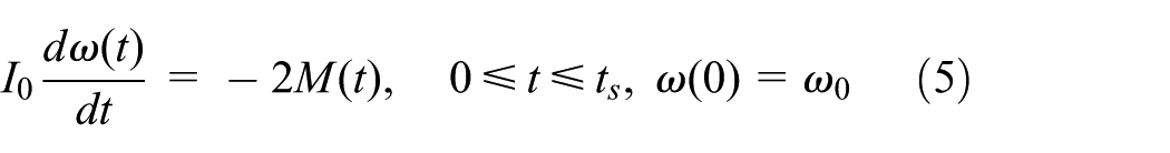
the change in the angular velocity during braking will be determined from the solution of the initial value problem for the equation of motion
where
is the moment of inertia of the friction couple with the initial kinetic energy
is the braking torque
is the equivalent radius of the contact region ,24 and and are the inner and outer radii of the pad (nominal area of contact), respectively. It is should be noted that for calculations of temperature in the pad–disk tribosystem, typically the following formula is used25
which is a special case of formula (8), at small values of the cover angle .
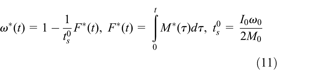
The solution of the initial value problem (equations (4)–(8)) has the form
where
Taking into account the solution (equations (10) and (11)), from the condition of a stop , the functional equation for the calculation of the total braking time is obtained
It should be noted that when the contact pressure p (equation (4)) reaches the nominal value instantly , and the coefficient of friction is constant ; then from formulas (7) and (11), , , , and . Thus, the parameter (equation (11)) represents the time to a stop at braking with constant deceleration.
Temperature on the nominal area of contact
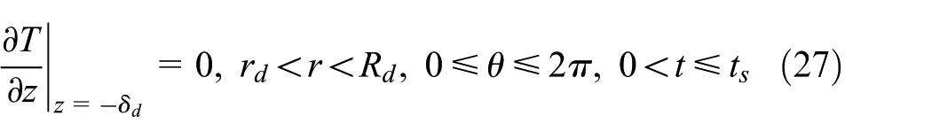
Due to the geometric and load symmetry of the analyzed braking system, only one pad sliding on a disk of a thickness , with adiabatic condition on a surface in the midplane, will be taken into consideration. In a cylindrical coordinate system , the pad and the disk occupy the regions and , respectively (Figure 1). The nominal contact region is denoted , and its area is equal to .
To determine the change in the mean temperature during braking
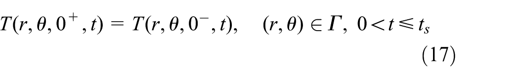
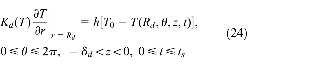
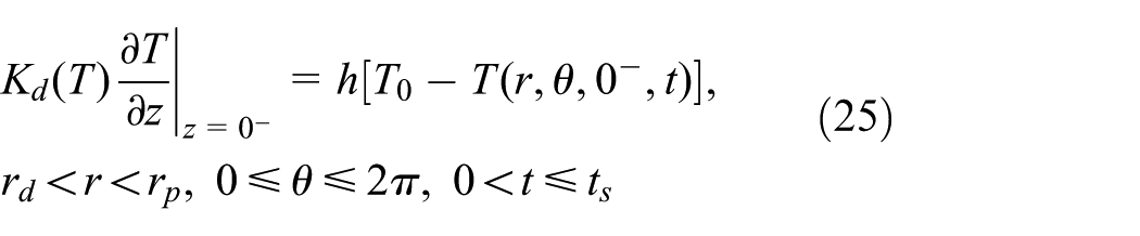
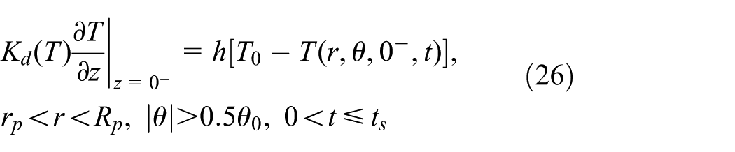
the distribution of temperature on the contact region has to be known. Assuming the perfect thermal contact of friction between the pads and the disk, the distribution of the transient 3D temperature field in the pad–disk tribosystem will be found from the solution of the following non-linear boundary value heat conduction problem
where
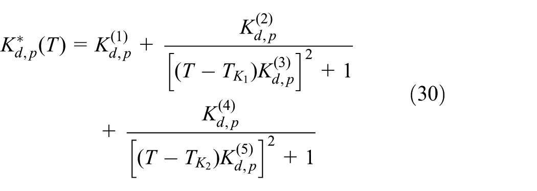
, and , are the coefficients approximating the experimental data on the temperature dependence of the thermal conductivity and specific heat for the materials of the disk and the pads.
The specific friction power appeared in the boundary condition (equation (16)) is equal to15,16
where the dependence of the coefficient of friction f on the maximum temperature (equation (1)) has the form of equations (2) and (3).
Flash temperature
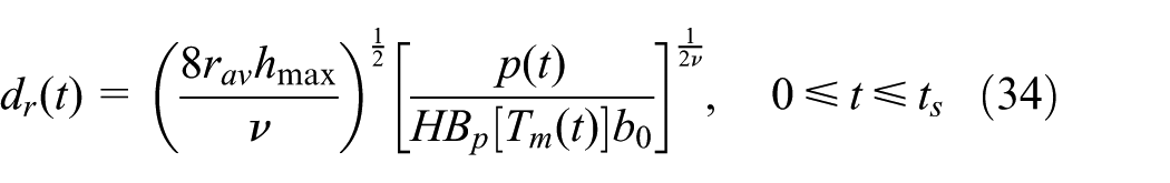
Surface asperities of the sliding bodies are subject to elastic, elastic–plastic, and plastic mechanisms of deformation.26,27 The temperature of discrete zones of rough surfaces during frictional heating is termed the flash temperature.9 During the plastic deformation, one of the materials of the friction couple has noticeably smaller hardness, rigidity, and roughness. Usually, it is a material of brake pads. Plastic micro-contact during braking is the most likely, due to a significant amount of mechanical energy being converted into heat in a short period of time. The parameters characterizing the flash temperature are the real area of contact and the diameter of an average spot of a real contact . In the case of plastic mechanism of deformation, their changes are determined using the following formulas28
where the Brinell hardness of the pad material has the form
with and being known coefficients of approximation of the experimental data for the pad material, p the contact pressure (equation (4)), and the mean roughness radius and the maximum roughness height of the rigid element, respectively, and and being the parameters of the rigid element reference surface curve (usually a disk).29
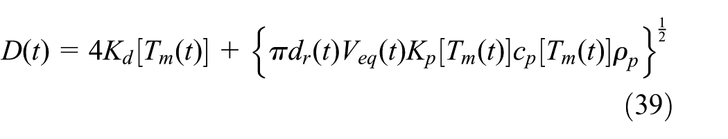
The formulas for calculating the flash temperature during braking were obtained using the monographs.2,24 With regard to the taken notation, those formulas can be written as
where
and the specific friction power q at the equivalent radius (equation (8)) is calculated from formula (32), the change in angular velocity over time is presented in formulas (10)–(12). The evolutions of the real area of contact and the diameter of an average spot of the real contact are obtained using formulas (33)–(36).
The calculation of temperature on the real contact spot depends on the correctness of the estimation of the individual parameters included in formulas (33)–(40). It can be seen that the flash temperature is determined not only by the parameters of friction and properties of materials, but also by the characteristics of contacting surfaces. It is known that the calculation of flash temperature without taking into account the temperature dependence of the thermophysical and mechanical properties of materials leads to incorrect estimation of , hence also (equation (1)).30 The values of thermal conductivity , specific heat , and hardness in formulas (33)–(40) were taken at the mean temperature (equation (13)) of the area of contact and are determined from the solution of the boundary value problem (equations (14)–(32)).
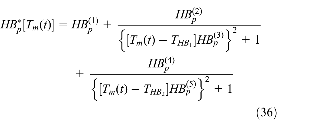
Use of the current values of physical properties of the materials, corresponding to the mean temperature , in the calculation of the flash temperature is obviously possible. Then the data of the current values of characteristics of the microgeometry of the sliding surfaces, practically do not appear. Usually, for calculating , the data obtained from the investigation of the contact surface of the component after the end of the process of frictional sliding are used. This assumes that the surface roughness, which has established after the break-in period, does not change during friction.31 However, it may be acceptable only for the stationary regime of friction. For non-stationary frictional heating, which takes place during braking, the roughness of the rubbing surfaces can be noticeably changed and consequently the characteristics of microgeometry in formulas (33)–(40). According to the hypothesis of summation of the temperature on frictional contact (equation (1)), the value of the flash temperature depends on the mean surface temperature , which affects the mechanical and thermophysical properties of the contacting asperities, and therefore the size of the real area of contact. The experimental studies have shown that the flash temperature decreases with an increase in the mean temperature.32 It was found that the relationship between and has the form3
where the dependencies of the parameters B and C on the contact pressure p (equation (4)) and the sliding velocity (equation (40)) were obtained in Mamchegov et al.33 It was shown that these relations can be approximated in the following form3
where are the known coefficients.
The use of formulas (41) and (42) allows reducing significantly the calculation time of flash temperature, since having the coefficients eliminates the introduction of the dependencies of the mechanical and thermophysical properties of materials, as well as changes in parameters of microgeometry of the friction surface during braking. The calculations based on formulas (41) and (42) were verified experimentally by the character of the structural transformations in a thin subsurface layer, and their good convergence has been established in the assessment of the maximum temperature (equation (1)).34
Wear
The change in braking time of the amount of wear I of the friction surfaces of the pad–disk system was calculated by the formula35
where Q is the friction power (equation (38)), whereas the dependence of the wear rate on the maximum temperature (equation (1)) has the form
General recommendations for determining the coefficients and , can be found in a previous study.36
Some details of calculations
All the three problems of the HDFW system of equations, namely, the initial value problem for the equation of motion (5) and its solution (equations (10)–(12)), the boundary value problem of heat conduction (equations (14)–(32)) for determining the mean temperature (equation (13)), and the formulas (33)–(40) or (41) and (42) for the calculation of flash temperature , are interrelated through the coefficient of friction f (equations (2) and (3)), dependent on the maximum temperature (equation (1)). The solution of the HDFW system of equations, for the pad–disk friction couple, was obtained using the implicit time-stepping algorithm—a backward differentiation formula (BDF) with an adaptive time step.37 The algorithm seeks the solutions at up to five previous time steps to find the solution at the next time step.
The solution of the boundary value non-linear heat conduction problem (equations (14)–(32)) was obtained using the FEM implemented in COMSOL Multiphysics® version 5.3 software.37 The 3D FE mesh of the pad–disk braking system used in thermal analysis is shown in Figure 1. The computational region was divided into 8520 second-order hexahedral elements (1320 elements for the pad and 7200 elements for the disk). The number of degrees of freedom (DoFs) solved was equal to 308343. The minimum element size was equal to 0.917 mm and the maximum element size was 6.02 mm.
The dimension of elements in the z-direction decreased with the distance from the contact surface , both for the disk (four elements) and for the pad (six elements). The ratios of the largest to the smallest element were 2 and 4 for the disk and the pad, respectively. In the radial direction, also non-uniform distribution of elements was set. The strict time step Δt for the results shown was equal to , except for the temperature T from Figure 4, for which the time step was equal to .
In order to calculate the flash temperature (equation (37)), it was necessary to have the friction power Q (equation (38)), which depends on the coefficient of friction . Therefore, for calculations of the coefficient of friction on the nth time increment , the iterative procedure with at has been established. Based on this relationship, the software finds the solution of the initial value problem for the equations of motion ((10)–(12)). The calculations were performed until reaching the braking time through checking the condition .
Numerical analysis
The procedure outlined in the previous sections is applied to the simulation of the braking process under the operating parameters shown in Table 1. Three different pad materials—the cermet FMC-11 (64% Fe, 15% Su, 3% SiO2, 6% BaSO4, 3% of asbestos, and 9% graphite), MCV-50 (64% Fe, 10% Сu, 5% V4С, 5% SiC, 5% FeSO4, and 3% of asbestos), and the FC-16L Retinax (produced on the basis of phenol–formaldehyde resins and reinforced by a wire with the addition of the brass shavings)—combined with the cast iron ChNMKh brake disk were examined. The values of the thermophysical , (equation (29)) and mechanical (equation (35)) properties of the materials at the initial temperature are listed in Table 2. In the same table, the approximation coefficients, for the dimensionless functions (equation (30)), (equation (31)), and (equation (36)) are presented. The graphs of these functions are shown in Figure 2. One should note that the thermophysical properties of the above-mentioned materials, except for the FC-16L Retinax, are temperature dependent. The density values are 7100, 4700, 5300, and 2500 kg m−3 for ChNMKh, FMC-11, MCV-50, and FC-16L, respectively.
Operating parameters for thermal analysis.
Parameter
Value
Mechanical work per one braking system Ws (kJ)
50.7
203
456.7
812
Initial velocity on the equivalent radius Veq (m s−1)
5
10
15
20
Nominal contact pressure p0 (MPa)
1.47
Heat transfer coefficient h (W m−2 K−1)
60
Initial/ambient temperature T0 (°C)
20
Rise time tm (s)
0.5
Inner/outer radius of the disk rd/Rd (mm)
66/113.5
Inner/outer radius of the pad rp/Rp (mm)
76.5/113.5
Cover angle of the pad θ0 (rad)
1.126
Coefficients in the approximation formula for the dependencies of the thermophysical properties of materials , and Brinell hardness on temperature T.
FMC-11
35
1.125
−0.6393
900
0
0
0
MCV-50
30.78
−0.0621
0.5717
−2037
0.544
−100
FC-16L
0.79
–
–
–
–
–
–
–
ChNMKh
52.17
4.223
−2543
0
0
0
FMC-11
478.9
0.7748
0.7385
1059
0.4992
573
MCV-50
397.3
−0.786
2.759
1306
0.02
44
FC-16L
961
–
–
–
–
–
–
–
ChNMKh
444.6
−0.8461
6.598
4903
1.372
443
FMC-11
1372.9
−0.926
0.823
546
2.02
−233
MCV-50
1225.8
−0.5665
1.08
−246
0.553
−57
FC-16L
392.3
−0.686
1.271
362
41.7
−141
Dependencies of the dimensionless thermal conductivity , specific heat , and Brinell hardness on the temperature T for cast iron ChNMKh (solid line), FMC-11 (dashed line), MCV-50 (dotted line), and FC-16L (dash-dot line).
The components of the HDFW system of equations, essential to perform calculations, are the temperature dependencies of the coefficients of friction (equation (2)) and the wear rate (equation (44)). The values of these parameters at the initial temperature and , as well as the coefficients in dimensionless functions (equation (3)) and (equation (45)) for the three friction couples analyzed, are presented in Table 3. The functions and are plotted in Figure 3. These dependencies are usually obtained as a result of processing of the experimental data from the experimental studies on the heat stability of the friction couples.20
Coefficients in the formula for the dependencies of the coefficient of friction f and wear rate I on the temperature T at the nominal contact pressure .
FMC-11
0.839
0.602
0.437
105
0.672
790
MCV-50
0.543
0.282
1.877
−300
1.877
870
FC-16L
1.479
0
3.412
850
0.93
0
f1
f2
f3 (°C−1)
f4
f5 (°C−1)
FMC-11
0.45
1.071
−250
0
0
0
MCV-50
0.45
0.08
0.26
−167
0.73
−106
FC-16L
0.28
0.072
1.041
95
0.723
800
Dependencies of the dimensionless coefficient of friction and coefficient of wear on the temperature T for the friction couple consisting of the cast iron disk and pad made of FMC-11 (dashed line), MCV-50 (dotted line), and FC-16L (dash-dot line).
The evolution of the mechanical work was calculated by the formula
where is the current friction power (equation (38)). In order to compare the obtained results, the mechanical work was kept constant , for all of the three friction couples and the applied input parameters. The calculations were conducted at the four initial velocities , and the corresponding mechanical work done per one braking system is shown in Table 1.
The flash temperature was calculated using two different approaches. The first of them (variant 1) is based on the formulas (33)–(40) and uses the following parameters of roughness of the friction surface of the rigid material (cast iron disk): , , , and .2 The corresponding values of the coefficients , which were used in the calculations according to formulas (41) and (42) (variant 2) are presented in Table 4.2,33 The results of calculations, shown in Figures 4–8 for each of the three analyzed friction couples, obtained using variant 1 are marked with solid lines, whereas the dashed lines correspond to those obtained using variant 2. When analyzing the obtained results, it should be taken into account the fact that the set of dimensionless time , in Figures 4, 5, 6, and 8, requires specific approach, for example, the maximum values reached can occur at different moments of braking time.
Coefficients in formulas (41) and (42) to calculate the flash temperature (variant 2) for the three pad materials combined with cast iron disk.
Pad material
FMC-11
0.981
2 × 10⁻²
1.9 × 10⁻³
MCV-50
1.177
2 × 10⁻²
1.9 × 10⁻³
FC-16L
4.609
4 × 10⁻²
2.0 × 10⁻³
Changes in the flash temperature on the contact surface during braking for cast iron disk and the pad made of (a) FMC-11, (b) MCV-50, and (c) FC-16L. Solid line represents the calculation of using variant 1 and dashed line using variant 2.
Changes in the mean temperature on the contact surface during braking for cast iron disk and the pad made of (a) FMC-11, (b) MCV-50, and (c) FC-16L. Solid line represents the calculation of using variant 1 and dashed line using variant 2.
Changes in the maximum temperature on the contact surface during braking for cast iron disk and the pad made of (a) FMC-11, (b) MCV-50, and (c) FC-16L. Solid line represents the calculation of using variant 1 and dashed line using variant 2.
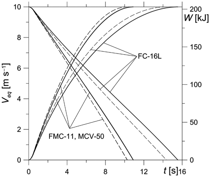
Evolutions of the sliding velocity and the mechanical work W for . Solid line represents the calculation of using variant 1 and dashed line using variant 2.
I of the pad and the disk working surfaces for . Solid line represents the calculation of using variant 1 and dashed line using variant 2.
The flash temperature increases rapidly at the beginning of the braking process and reaches the maximum value, approximately at the same time for each of the three pad materials, and both variants of calculation of (Figure 4). However, for the second variant, the flash temperature decreases more rapidly after reaching the maximum. When increasing the initial velocity , the dimensionless time of reaching the peak value of the flash temperature decreases. It shows that for longer braking durations the flash temperature becomes less important. The time of reaching the peak value of for all of the studied velocities and materials is in the range . Selection of one out of the two variants considered affects the peak values of the flash temperature , particularly at high initial velocities and for harder materials of the pads (Table 5). It was also found that all of the obtained results are similar for the pads made of cermet materials (FMC-11, MCV-50). This stems directly from comparable properties of materials and their dependencies on temperature (Figures 2 and 3).
Peak values of temperature at two variants of their calculation for the three studied pairs of materials and four initial velocities .
Peak value of temperature
Pad material
FMC-11
MCV-50
FC-16L
Variant of
1
2
1
2
1
2
154
143.9
141.9
135
74
70
234.2
188.9
215.5
177.4
118.7
97.8
288.8
215.1
264.5
202.7
148.2
116.2
330.4
234
301.5
220.2
170.8
129.5
Evolutions of the mean temperature , determined by formula (13) on the basis of the transient temperature field , are shown in Figure 5. In addition, changes in temperature for the fixed point on the friction surface of the brake disk T(, , ) at the velocity of are presented. The mean temperature change , determined by this analysis at the linear initial velocities of and , agrees with the corresponding results of calculations carried out in Yevtushenko and Grzes,17 obtained for the same dimensions of the braking system, but constant properties of materials, coefficient of friction dependent on the mean temperature , and a nominal contact pressure of 1.47 MPa. In that study, the peak value of the mean temperature, at the analyzed initial velocity ( at the wheel radius ), was approximately equal to .
As shown in Figure 5, an increase in the mean temperature for each studied velocity is smooth. This is partly an effect of the applied contact pressure and a result of change in the specific friction power.38 An influence of the flash temperature on the mean temperature is insignificant—for any initial velocity, the mean temperature for the two variants considered almost coincides. A slight difference is more evident at the highest of the studied initial velocities . It can be seen that the mean temperatures obtained using the cermet pads are almost equal (Figure 5(a) and (b)), whereas the maximum value of and its change during braking vary for the pads made of FC-16L Retinax (Figure 5(c)). It is also necessary to note that at low initial sliding velocities the maximum values of the mean temperatures for the cermet pads are smaller than the corresponding peak values of the flash temperatures. Probably, this is due to the fact that the hardness of the cermet materials (FMC-11, MCV-50) is considerably (almost three times) higher than that of FC-16L Retinax.
The evolutions of the maximum temperature during braking are shown in Figure 6. The maximum temperature is more “sensitive” to the selection of the computational variant of the flash temperature than the mean temperature on the pad–disk contact surfaces. For the specified variant of calculation of the flash temperature, the difference between the corresponding values of the mean and maximum temperatures is the most significant at the initial stage of braking, when the flash temperature is the highest. With the increase in the braking time and the heating of the rubbing surface, this difference decreases.
The corresponding results (Figures 4–6) obtained using the analytical methods for the simplified geometrical model of the shoe brake were obtained using the monograph.19 The drum was made of steel 30KhGSA with similar thermophysical properties to cast iron ChNMKh used in this study, and the shoe was made of FC-16L Retinax. It was found that the peak value of the flash temperature at braking from the initial velocity of (braking time 3 s, contact pressure 0.5 MPa) was equal to 450°C. This value was three times higher than the mean temperature of the nominal contact region of the drum and two times higher than the corresponding value for the shoe .
The changes in the velocity and the mechanical work W (equation (46)) occurred during braking at are shown in Figure 7. Except for the short time interval at the beginning, decreases almost linearly. It can also be seen that an effect of flash temperature on the duration of braking is evident. The braking time for the first variant of calculations of the flash temperature is longer than that for the second by 8% when the pads are made of FC-16L Retinax and by 6% for cermet materials (FMC-11 and MCV-50). According to the formulated initial value problem for the equation of motion for each studied pair of materials and at the given initial velocity, the mechanical work is equal to , whereas the braking time varies. This approves the carried out comparisons of the obtained results. The differences in braking durations for the examined materials stem from the applied changes in the coefficient , where in this study is 0.45 (cermet) and 0.28 (Retinax A) (Table 3). Other approach, as reported in Belhocine and Omar,39 is to find the coefficient of friction from complex relations and methods (e.g. Lagrange multipliers) implemented in thermomechanical analysis.
Changes in the wear rate I (equations (43)–(45)) during braking are shown in Figure 8. The amount of wear increases monotonically over time, reaching a maximum value at the stop. By comparing all the solid and dashed curves in Figure 8, it may be easily observed that the selection of the variant for the calculation of flash temperature affects wear, both for the cermet and Retinax pads. The least value of wear over the braking duration was obtained for the cermet MCV-50 pads and was the highest for the pads made of FC-16L Retinax. This corresponds with the values of the initial coefficients of wear rate (equation (44)) shown in Table 3. In the case of the pads made of Retinax, the mass of the material worn at the stop , found using variant 1, is 5.5% lower than the corresponding mass obtained by means of variant 2.
Summary and conclusion
Computer simulations of a single braking to study the flash temperature, found based on two Chichinadze’s methods, as well as mutual influence with the braking parameters, were carried out. The proposed spatial model of the disk brake is an extension of the axisymmetric 2D model using the first computational variant of the flash temperature (equations (33)–(40)).16 The analysis of the three different materials of the brake pads and four initial velocities in the range from 5 to 20 m s−1, covering the majority of cases occurring under real conditions of braking of motor vehicles, allowed formulating the following conclusions:
The flash temperature (variants 1 and 2) calculated on the basis of the spatial system differs slightly compared to the corresponding results obtained by means of the axisymmetric model.16 As observed, the flash temperature has significant influence on the hardness of the material. In the case of brake pads made of FMC-11 and MCV with the Brinell hardness values of and 1225.8 MPa, respectively, compared to FC-16L material with a hardness of , it led to an approximately two times higher flash temperature, at each of the initial sliding velocities examined.
For the sliding velocity of of the two analyzed cermet materials (FMC-11 and MCV-50), the flash temperature is lower than the average temperature of the nominal contact region. Below that velocity, exceeds an average temperature . However, for the softer material (FC-16L), is less important.
Temperature changes (Figures 4–6), at the velocity of , are nearly coincident for all the materials. Above that velocity, the differences increase to around at .
The best agreement of the flash temperatures (variants 1 and 2) was obtained at the beginning of the heating process until reaching the maximum and at the moment of stopping. Approximately in the middle range of the braking time , the flash temperature calculated using variant 1 is higher than the corresponding value calculated by the second variant, for each velocity and each material.
The peak values of the mean and the reached maximum temperature calculated by means of the two different approaches vary slightly when the initial velocity is high . Since the maximum flash temperature is reached at the beginning unlike the mean dominant temperature, the resulting maximum temperature remains unchanged even for greater difference in the flash temperature.
Durations of braking determined using both variants calculated for differ by 6% for cermet and by 8% for Retinax material.
The impact of the method of calculation of on the amount of wear, at the velocity of , is the most noticeable at the end of braking for the pad made of FC-16L Retinax. This is a complex relation of several parameters and properties of materials but the most direct are the function of temperature dependence of wear and the constant value of corresponding to the temperature of 20°C. As shown in Table 3, for cermet material is equal to for FMC-11 and for MCV-50.
The carried out calculations are an attempt to gain a better understanding of the influence of flash temperature on the frictional heating during the braking process. In reviewing the temperature curves shown in Figure 4, it might be concluded that the empirical formulas based on the relationship between the flash temperature on the real area of contact and the mean temperature of the nominal area of contact are fully justified in estimating the maximum temperature of the pad–disk tribosystem. Experimental methods of obtaining such formulas for the single braking, including the construction of the nomograms, were presented in the literature.2,33,34
Footnotes
Appendix 1
Handling Editor: Noel Brunetiere
Declaration of conflicting interests
The author(s) declared no potential conflicts of interest with respect to the research, authorship, and/or publication of this article.
Funding
The author(s) disclosed receipt of the following financial support for the research, authorship, and/or publication of this article: This study was performed within the framework of the research project No. 2015/19/D/ST8/00837 financed by the National Science Centre, Poland.
ORCID iD
Piotr Grzes
References
1.
BogdanovichPNTkachukDV.Thermal and thermomechanical phenomena in sliding contact. J Frict Wear2009; 30: 153–163.
2.
ChichinadzeAVBraunEDGinsburgAGet al. Designing, testing and selecting frictional couples. Moscow: Nauka, 1979 (in Russian).
3.
ChichinadzeAV.Processes in heat dynamics and modelling of friction and wear (dry and boundary friction). Tribol Int1995; 28: 55–58.
4.
ChichinadzeAV.Theoretical and practical problems of thermal dynamics and simulation of the friction and wear of tribocouples. J Frict Wear2009; 30: 199–215.
5.
GinzburgAG.Theoretical and experimental bases for calculation of the single braking process with help of the system of equations of heat dynamics of friction, optimal use of friction materials in friction units of machines. Moscow: Nauka, 1973, pp 93–105 (in Russian).
6.
AwrejcewiczJPyryevYu.Nonsmooth dynamics of contacting thermoelastic bodies. New York: Springer, 2009.
7.
YevtushenkoAAKuciejM.One-dimensional thermal problem of friction during braking: the history of development and actual state. Int J Heat Mass Trans2012; 55: 4118–4153.
8.
JaegerJC.Moving sources of heat and the temperature of sliding contacts. J Proc R Soc NSW1942; 76: 203–224.
9.
BlokH.The flash temperature concept. Wear1963; 6: 483–494.
10.
KennedyFE.Frictional heating and contact temperatures. In: BhushanB (ed.) Modern tribology handbook. Boca Raton, FL: CRS Press, 2001, pp.235–272.
11.
ChichinadzeAVKozhemyakinaVDSuvorovAV.Method of temperature-field calculation in model ring specimens during bilateral friction in multidisk aircraft brakes with the IM-58-T2 new multipurpose friction machine. J Frict Wear2010; 31: 23–32.
12.
BelhocineAOmarWZW. CFD analysis of the brake disc and the wheel house through air flow: predictions of surface heat transfer coefficients (STHC) during braking operation. J Mech Sci Technol2018; 32: 481–490.
13.
BelhocineA.FE prediction of thermal performance and stresses in an automotive disc brake system. Int J Adv Manuf Technol2017; 89: 3563–3578.
14.
YevtushenkoAAGrzesPAdamowiczA.Numerical analysis of thermal stresses in disk brakes and clutches (a review). Numer Heat Transfer Part A2015; 67: 170–188.
15.
YevtushenkoAAGrzesP.Maximum temperature in a three-disc thermally nonlinear braking system. Int Commun Heat Mass Transfer2015; 68: 291–298.
16.
GrzesP.Determination of the maximum temperature at single braking from the FE solution of heat dynamics of friction and wear system of equations. Numer Heat Transfer Part A2017; 71: 737–753.
17.
YevtushenkoAAGrzesP.3D FE model of frictional heating and wear with a mutual influence of the sliding velocity and temperature in a disc brake. Int Commun Heat Mass Transfer2015; 62: 37–44.
18.
YevtushenkoAAGrzesP.Mutual influence of the sliding velocity and temperature in frictional heating of the thermally nonlinear disc brake. Int J Therm Sci2016; 102: 254–262.
19.
ChichinadzeAV (ed.). Polymers in friction assemblies of machines and devices: a handbook. New York: Allerton Press, Inc., 1984, p.280.
20.
ChichinadzeAVMatveevskiRMBraunEP.Materials in tribotechnics non-stationary processes. Moscow: Nauka, 1986 (in Russian).
21.
YevtushenkoAAGrzesP.Axisymmetric finite element model for the calculation of temperature at braking for thermosensitive materials of a pad and a disc. Numer Heat Transfer Part A2012; 62: 211–230.
22.
YevtushenkoAAKuciejMOchEet al. Effect of the thermal sensitivity in modeling of the frictional heating during braking. Adv Mech Eng2016; 8: 1–10.
23.
GaoCHLinXZ.Transient temperature field analysis of a brake in a non-axisymmetric three-dimensional model. J Mater Proc Tech2002; 129: 513–517.
24.
ChichinadzeAV.Estimation and investigation of external friction during braking. Moscow: Nauka, 1967 (in Russian).
25.
WauerJSchweizerB.Dynamics of rotating thermoelastic disks with stationary heat source. Appl Math Comput2010; 215: 4272–4279.
26.
KragelskyIVDemkinNB.Contact area of rough surfaces. Wear1960; 3: 170–187.
27.
BhushanB.Introduction to tribology. 2nd ed.New York: Wiley, 2013.
28.
DemkinNB.Contact of rough surfaces. Moscow: Nauka, 1970 (in Russian).
29.
DemkinNBKorotkovMAAlekseevVM.Method of calculating the characteristics of frictional contact, calculation and simulation of working mode of brake and friction devices. Moscow: Nauka, 1974, pp.5–15 (in Russian).
30.
PowellDIEarlesSWE. An assessment of surface temperature predictions in the high speed sliding of unlubricated SAE 1113 steel surfaces. Trans ASLE1972; 15: 103–112.
31.
KragelskyIVDobychinMNKombalovVS.Friction and wear: calculation methods. Oxford: Pergamon, 1982.
32.
EarlesSWEHaylerMGPowellDG.A comparison of surface temperature theories and experimental results for high speed dry sliding. Trans ASLE1971; 14: 135–143.
33.
MamchegovMAZinovyevaZVGinzburgAG.Questions of calculation of the maximum temperature at non-stationary friction with intensive heat generation, friction and wear. Moscow: Nauka, 1977, pp.46–53 (in Russian).
34.
MamchegovMA.Determination of the maximum temperature of the sliding contact. Mashinostroeniye1977; 1: 107–112 (in Russian).
35.
GinzburgAGChichinadzeAV.To calculation of wear during braking using the equations of thermal dynamics of friction, friction and wear of friction materials. Moscow: Nauka, 1977, pp.26–30 (in Russian).
36.
YevtushenkoAAGrzesP.Axisymmetric FEA of temperature in a pad/disc brake system at temperature-dependent coefficients of friction and wear. Int Commun Heat Mass Transfer2012; 39: 1045–1053.
37.
COMSOL Multiphysics®v. 5.3. www.comsol.com. COM SOL AB, Stockholm, Sweden.
38.
YevtushenkoAAKuciejMTopczewskaK.Analytical model for investigation of the effect of friction power on temperature in the disk brake. Adv Mech Eng. Epub ahead of print 11 December 2017. DOI: 10.1177/1687814017744095
39.
BelhocineAOmarWZW. Three-dimensional finite element modeling and analysis of the mechanical behavior of dry contact slipping between the disc and the brake pads. Int J Adv Manuf Technol2017; 88: 1035–1051.