
Abstract
In order to enhance the efficiency of the image transmission system and the robustness of the optical imaging system of the Association of Sino-Russian Technical Universities satellite, a new framework of on-board cloud detection by utilizing a lightweight U-Net and JPEG compression strategy is described. In this method, a careful compression strategy is introduced and evaluated to acquire a balanced result between the efficiency and power consuming. A deep-learning network combined with lightweight U-Net and Mobilenet is trained and verified with a public Landsat-8 data set Spatial Procedures for Automated Removal of Cloud and Shadow. Experiment results indicate that by utilizing image-compression strategy and depthwise separable convolutions, the maximum memory cost and inference speed are dramatically reduced into 0.7133 Mb and 0.0378 s per million pixels while the overall accuracy achieves around 93.1%. A good possibility of the on-board cloud detection based on deep learning is explored by the proposed method.
Introduction
As far as the CubeSat satellites are concerned, the capability of the data transmission system would be largely limited by power consumption and covering time due to its low cost and lack of ground stations.
For example, The Association of Sino-Russian Technical Universities (ASRTU) satellite is designed by the Research Center of Satellite Technology (RCST) in Harbin Institute of Technology (HIT). The planned launch time is in 2019. The sketch of ASRTU is illustrated in Figure 1. And its hardwares and corresponding parameters related to optical payload are shown in Figure 2. Take the LilacSat-2 satellite as a reference which was also designed by HIT and launched on 20 September 2015. With downlink frequency of 437.2 MHz and orbit height of 524 km, the downlink data rate is less than

The sketch of the ASRTU satellite.
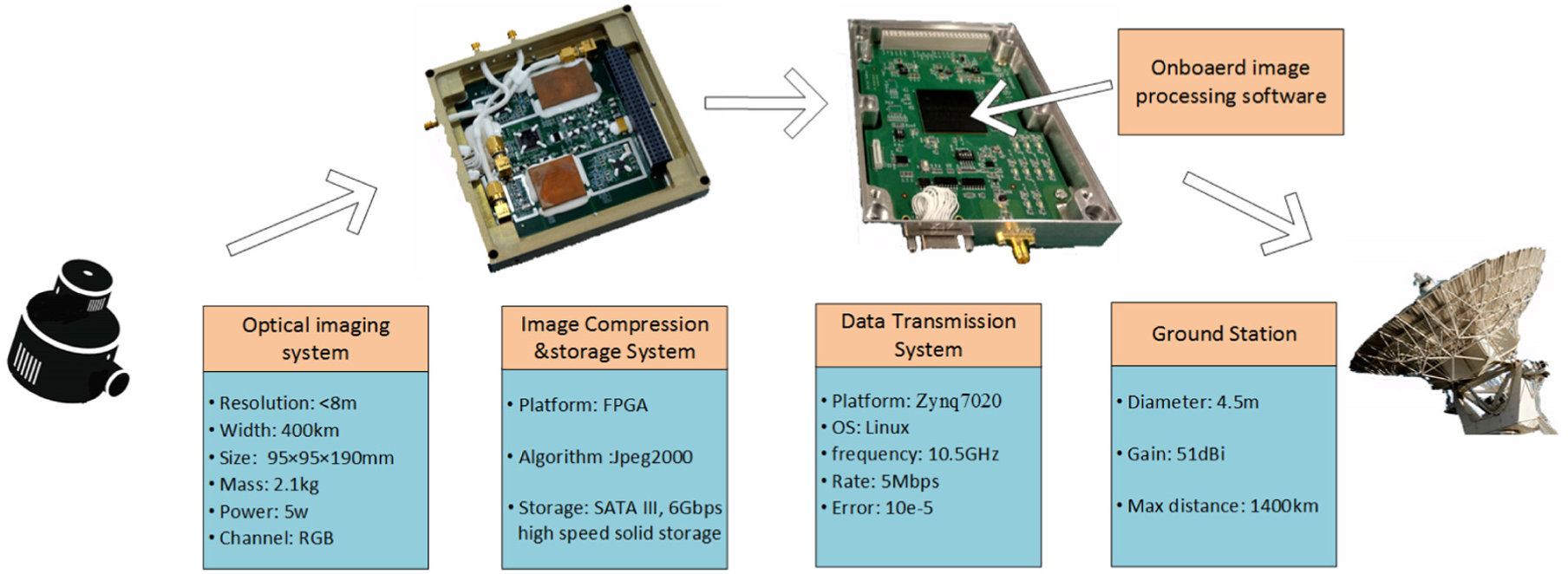
Hardwares and parameters of the ASRTU satellite.
On the other hand, over 66% of the land surfaces on Earth is covered by cloud, and it often appears and covers objects on the surface in remote-sensing (RS) images to make much difficulty for further image processing. Therefore, it is necessary to apply the on-board image cloud-detection algorithms in the ASRTU mission.
Generally, it is difficult to deploy the creative and novel classification algorithms in the satellite platform for several reasons, such as the requirement of high reliability in satellite engineering and the real-time demands for numerous downlink data. The development of the CubeSat satellites demonstrates a solid edge for the verification of the novel missions such as on-orbit RS justification, 1 space debris identification,2,3 visual navigation aids,4,5 and others.
In recent years, the impressive results of deep-learning networks for computer vision applications brought fresh air to the satellite applications. Real improvements in several applications could be observed such as image classification and scene recognition, image retrieval, and many others. Deep-learning method offers a great opportunity for breakthroughs of the on-board optical sensor data processing, especially in CubeSat missions. However, the mainstream deep-learning networks require extremely high computation capability of hardware, which is intolerable for the platform of the small satellites. Therefore, two strategies are applied here to improve the efficiency of the network. First, considering that the JPEG2000 compression method is utilized in ASRTU mission as demonstrated in Figure 2, a careful compression strategy is required to create the low-resolution images for image classification and detection. Furthermore, the image processing algorithm would be deployed on the compressed images to reduce the required memory of the network. Second, several improvement such as lightweight network layers, depthwise separable convolutions are introduced to shrink the network and improve its inference speed.
Many different machine-learning algorithms have been applied in cloud detection for recent years,6–9 while few of them considers on-board cloud detection. The IPEX mission by NASA in 2013 is the first time that a machine-learning system has been trained on a sub-orbital flight and then successfully utilized on orbit. 10 However, the data compression problem is not under its consideration due to the low-resolution raw images. The STU mission launched on 25 September 2015 utilized the optical sensor data taken from Antarctic region to calibrate its exact position with the openly available Modis 250 data. 4 In addition, random forest method is introduced into the hyperspectral images for object classification.11,12 An improved texton-based approach is demonstrated in article 13 to categorize the cloud image patches. In addition, article by Lin et al. 6 introduces a cloud-removal approach based on information cloning which could remove cloud-contaminated portions of a satellite image and then reconstruct the information of missing data utilizing temporal correlation of multitemporal images. Besides, a green channel background subtraction adaptive threshold (GBSAT) algorithm is applied in the green channel of the visual images 14 to detect the cloud automatically.
To summarize, the main contributions of this work are: (1) a novel framework including special image-compression strategy and a lightweight U-Net combined with depthwise separable convolutional layers for cloud detection and (2) verification and comparison of two mainstream semantic segmentation networks and three wavelets for image compression.
The article is structured as follows. Section “JPEG2000 compression system” gives a brief recap of JPEG2000 compression and a carefully designed compression framework in order to provide the image input for the proposed deep-learning models, introduced in section “Deep-learning classification.” The experiment of the model training and test using different algorithms is illustrated in section “Experiment results,” while the conclusion and discussion in section “Conclusion and discussion.”
JPEG2000 compression system
JPEG2000 is an international standard compression technology based on wavelet transform, created and maintained by Joint Photographic Experts Group. 15 It is a powerful and convenient tool which is widely utilized in RS image processing and storage. The JPEG2000 compression standard enables both lossless and lossy storage and became popular for its two major advantages: progressive transmission and region of interest coding. 16 Progressive transmission means that in the image transmission process, the general content of the image would be transmitted first, before the details of the image information. 17 With the gradual increase of the received image data, higher resolution pictures would be created. In this task, the compression system with progressive transmission would help the satellite platform judge and classify the RS images on orbit by using compressed images. Furthermore, the satellite bandwidth would be saved since the compressed images covered by thick cloud could be detected. The architecture of the basic JPEG2000 encoder and decoder are shown in Figure 3.

Basic architecture of JPEG2000 encoder and decoder.
Basic discrete wavelet transform
In Figure 3, the discrete wavelet transform (DWT) would be utilized to reduce the image size without losing much of the resolution. 18 It could be applied to a whole original image and provide a different level of decomposition with image coefficients blocks, and the block of the transformed coefficients are classified into types like High-High (HH), High-Low (HL), Low-High (LH), and Low-Low (LL). These types are described as diagonal, horizontal, vertical, and image approximation. The sub-band structure generated by a three-level DWT algorithm on an original image is depicted by Figure 4.

Three-level DWT sub-band structure.
Where H0 and H1 represent the row transformation and column transformation of the DWT, respectively. After two transformations a new image with half resolution in two directions would be obtained, which is the LL in Figure 4. Furthermore, the decomposition process of the multi-level DWT and the results of each level decomposition are shown in Figure 4. The image block in upper left corner named by LL represents the low-frequency coefficient of the raw image, which could be treated as the image approximation of the original image, while other three different types contains the high-frequency coefficients along with the details of the raw image. When the DWT method reaches higher level, compressive images with lower resolution could be retrieved, which shows one of the good nature of DWT method: multi-resolution compression.
In the image matrix subjected to wavelet transform, the elements in the upper left corner (LL) show the average of the pixel values of the entire image, while the rest is the detail factor of the image block. According to this fact, if some high-frequency details of the coefficient are removed, it turns out that the reconstructed image quality is still acceptable. Furthermore, a large number of coefficients in the transformed matrix would become zero after the quantization process. Therefore, the matrix would become easier to be compressed without losing the accuracy by using a proper encoding method.
Progressive transmission
The operation platform of the compression system is based on a field-programmacle gate array (FPGA) processor in ASRTU satellite due to its efficiency requirement and power limit. However, the machine-learning algorithms are always deployed on a ARM processor, which means that the entropy decoding inverse quantization and inverse DWT are demanded in ARM processor to retrieve the raw image in low resolution. Therefore, the progressive transmission is introduced here to simplify the problem.
The definition of the progressive transmission is that reconstructing successively higher fidelity versions of an image along with the receiving data. The goal of the progressive transmission is thus not only efficient overall compression, but efficient compression at every step 19 especially under the condition while the data rate available for image transmission is unexpectedly low or the volume of the compressed data exceeds expectations. The progressive transmission would provide an opportunity to make more efficient usage of the data channel, since the less-value data would be detected in advance and not be transmitted with the original resolution.
There are several different types of the progressive transmission orders supported by JPEG2000 standard in different application scenarios. Take the component-position-resolution-layer (CPRL) order as an example, the brightness component in the outermost compression loop would be transmitted prior to the color component in the multispectral image transformation, which would guarantee maximum recovery of the original data with only the bright image when the other component of the data is not available. In this article, the resolution-position-component-layer (RPCL) order becomes a good choice to create the low-resolution images and encode them first.
Compression framework
In order to retrieve the low-resolution images from the compressed file without decoding and inverse quantization, a new compression framework is introduced. Considering that the compression algorithms and the machine-learning methods are deployed in different platform, the framework is expressed in Figure 5.
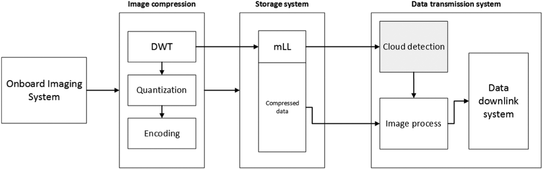
The proposed compression framework.
In Figure 5, one can see that the raw image obtained from on-board imaging system is introduced into the compression system. The mLL image means the m-level low-frequency image data after applying DWT, and it would be directly introduced into the machine-learning algorithm to detect the cloud, m could be adjusted by the resolution of the raw data and the training data of the machine-learning methods. The result of the methods would determine whether the compressed image is qualified to be transmitted to the ground station.
By utilizing the mLL images from the compression system, the cloud-detection system would calculate the cloud fraction of each image, and further decide the quality of the data. Considering the limited transmission resources for small satellites, the raw cloud data would be thrown away directly if its cloud fraction is above the default threshold. In addition, for images that are partly covered by cloud, the value in cloudy area would be transformed into zeros to improve the compression efficiency. The classification map combined with compressed images would be transmitted to the ground station in order to distinguish the cloud area.
It is worth mentioning that the mLL image block is retrieved without quantization and encoding. And the mLL data combined with other compression data are stored in the on-board hard disk in
Generally, the Le Gall 5/3 DWT would be the popular choice to obtain the mLL image data. The mLL data could be obtained by the following equation

where
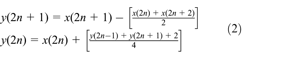
Besides, other wavelets such as Haar and Symlet could also be introduced to the image-compression system. The function of the two equations is well known, and the details can be seen in a study by Yadaiah and Ravi. 20 Therefore, m-level low-frequency DWT result would be restored after m times DWT operation.
Deep-learning classification
A standard artificial neural networks consists of many simple, connected processors called neurons, each producing a sequence of real-valued activations. These neurons are heavily inspired by way biological nervous systems (such as the human brain) operate. The basic structure of artificial nerual networks consists of input, hidden layers, and output. The hidden layers will make decisions from the previous layer and weigh up how a stochastic change within itself detriments or improves the final output, which is referred as learning.
Convolutional neural networks (CNNs) are analogous to traditional full-connected neural networks, from the input raw image vectors to the final output of the class score, the entire of the network will still express a single perceptive score function (the weight). The last layer will contain loss functions associated with the classes. 21 Compared with full-connected neural networks, CNN becomes much more popular in image detection tasks due to its great performance in the field of pattern recognition within images.
Pixelwise semantic segmentation
As far as the RS community, the progress of the on-orbit image processing is difficult due to the power and time limit of the satellite. For the ASRTU satellite, several requirements of the algorithm are listed in order to guarantee a good result in space. First, the algorithm needs to be fast enough since the time window of the downlink process is limited. Second, the algorithm operation platform is based on ARM9, which means algorithms that is vaguely complex and heavily depends on graphics processing unit (GPU) processors may be unacceptable. Third, the algorithm should be robust enough to deal with the complex electromagnetic environment in space. Deep-learning methods have been widely applied in different areas including RS image classification. However, most of the popular deep-learning networks contain more than 10 layers which reduce the possibility of on-board deployment due to the limited power and computation capability of the CubeSat satellite. Therefore, only the lightweight networks with fewer parameters should be considered here. In addition, unlike most cases, the size of the data set would exponentially reduce after image compression, and the existing deep-learning network combined with super pixel methods for cloud detection can hardly work. Therefore, the semantic segmentation neural network should be considered here to classify the cloud in the compressed data set.
Actually, there are two mainstream strategies for the pixelwise neural network. One is deconvolution network which was utilized in SegNet 22 and Deconv-Net. 13 Another is the upsampling layers which was utilized in fully convolutional network (FCN) 23 and U-Net. 24 Since the size of the cloud area varies from different scenes, the information from high-resolution layers should be remained and utilized in later layers. Therefore, U-Net with upsampling layers is introduced here as the main architecture of our network. Besides, the architecture of Deconv-Net with deconvolution layers is also introduced here to make a good comparison. The deconvolution layers is the transpose convolution layer to turn the convoluted images into their original size by reversing convolution. It would help the neural network achieve the pixelwise detection precision.
Depthwise separable convolutions
In order to further reduce the peak memory cost of the network in ARM processor and improve the inference speed of the network, the depthwise separable convolution from MobileNet
25
is illustrated and combined with the proposed network. The standard convolution operation includes two steps, one is filtering image features based on the convolutional kernels, another is combining features to produce a new representation. And the filtering and combination steps can be split into two steps by utilizing the factorized convolutions called depthwise separable convolutions for substantial reduction in computational cost. Depthwise separable convolution is composed of two layers: one is depthwise convolutions which apply a single filter in each input channel and remains the same channels after the convolution. Another is pointwise convolution, which uses simple


where C1 and C2 are, respectively, the convolution computation cost of the input layers and the output feature map, respectively. It is obvious that the depthwise convolution is extremely efficient relative to standard convolution. Generally, the
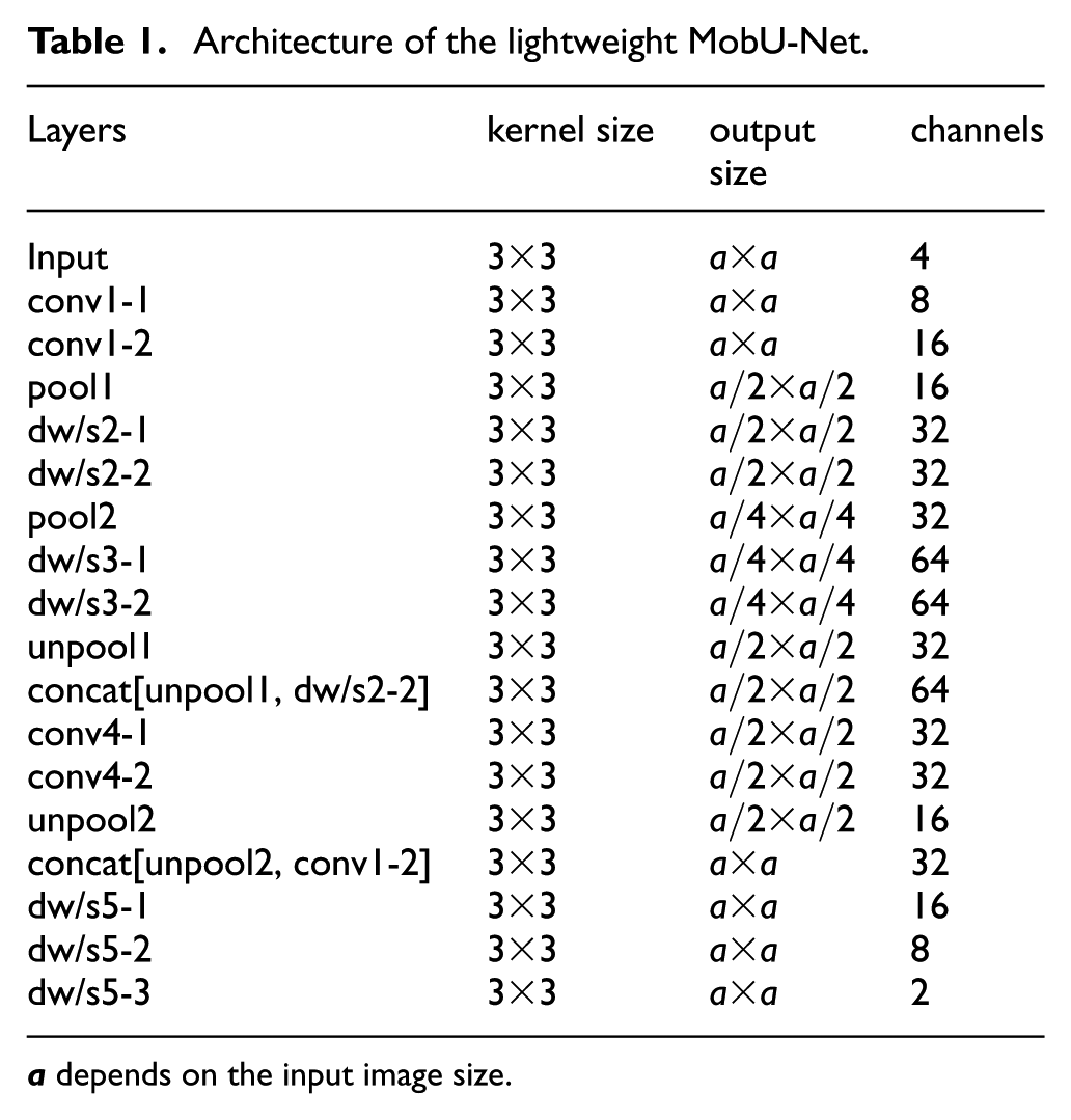
Combining with the depthwise separable convolution networks, the U-Net-based architecture MobU-Net and the Deconv-Net-based architecture MobDeconv-Net are illustrated in Tables 1 and 2, respectively. The
Architecture of the lightweight MobU-Net.
Architecture of the lightweight MobDeconv-Net.

Experiment results
The main objective of this article is to evaluate the generalization capacity of the effective deep-learning algorithms in on-board cloud detection for the ASRTU mission. In order to acquire better results, the open-source Landsat data SPARCS (https://landsat.usgs.gov/sparcs) is downloaded and utilized here as the training and test data set. The SPARCS data set was created by M. Joseph Hughes from Landsat 8 operational land imager (OLI) level-1B scenes. The overall images are separated into two groups: 80% as training set and 20% as test set. We carefully pick 12 representative scenes as test images and 64 scenes for training to make sure that every class is included and each class ratio in two groups keep approximately the same. The distribution of the scene for training and test is demonstrated in Figure 6. In order to make better simulation of the images from ASRTU satellite, several pre-processing steps are required here.
Considering that the ASRTU satellite products contains only four bands, in SPARCS data set only band 2, 3, 4, 5, which is red, blue, green, and infrared bands are utilized for training and testing, and the classes are reclassified as two classes including cloud and non-cloud.
All the images are splited into sub-scene with size of
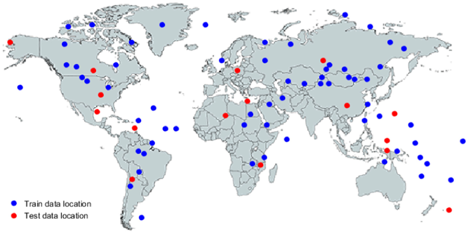
WRS2 path/row data location of imagery utilized for training and test.
All the networks are deployed in Windows-based TensorFlow environment with a single NVIDIA GTX-1060 GPU. The Google Cloud Platform is also utilized to train the data set.
The overall accuracy, recall, and F1-score are introduced here to evaluate the performance of different compression algorithms. F1-score could be retrieved from the following equation

where Acc means the overall accuracy, and Rec represents the recall of the neural network. The results of the neural network with different wavelets are illustrated in Tables 3–5, respectively.
Cloud-detection result of different networks with Haar wavelet.
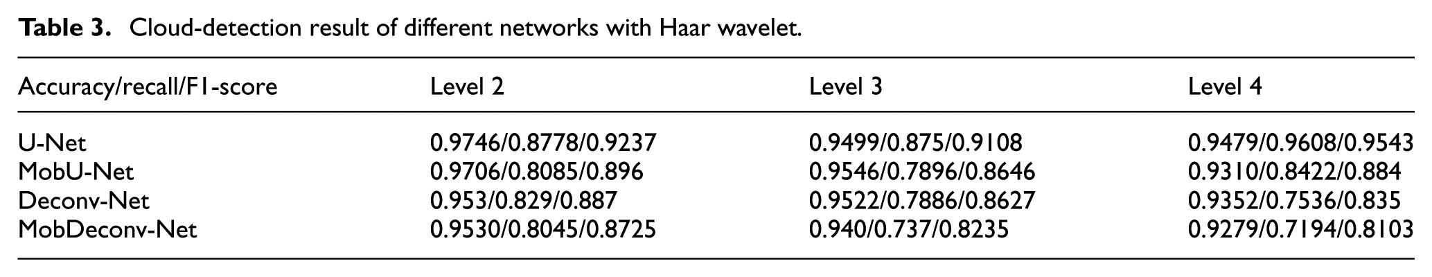
The architecture of the MobU-Net and MobDeconv-Net have already been demonstrated in Tables 3 and 4. The U-Net and Deconv-Net in the tables represent the lightweight U-Net and Deconv-Net with the same architecture in Tables 3 and 4, while the convolution process is achieved by the standard convolution layers. The results from the three tables show the following:
The overall accuracy and the recall are decreased when the depthwise separable convolutional layers are introduced into the networks, and its influence on the recall is more obvious.
Generally, U-Net shows the best performance on the data set with different levels and different wavelets. And correspondingly, MobU-Net illustrate higher F1-scores than MobDeconv-Net.
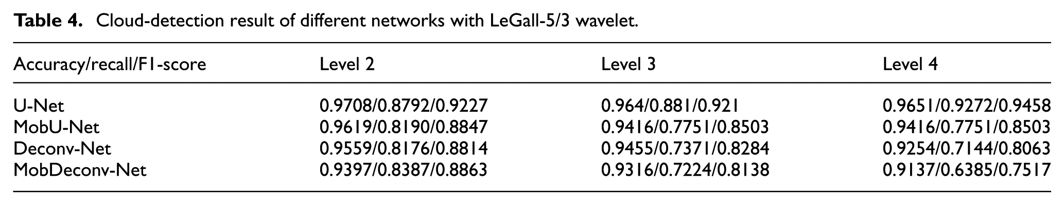
Cloud-detection results on Haar wavelet data set shows slightly better overall performance than other wavelets. For example, the recall of U-Net in Table 3 achieves 0.9543, while with other two wavelets the recall could only achieve 0.9272 and 0.7803, respectively. Considering that the high recall represents the low rate of the misclassified cloud areas, Haar wavelet is therefore selected in the JPEG2000 compression system for further process.
Cloud-detection result of different networks with LeGall-5/3 wavelet.
Cloud-detection result of different networks with Symlet-2 wavelet.

Table 6 demonstrates the average iteration time cost during training process for different networks with Haar wavelet. It is clear that the training time becomes shorter when the level of compression becomes deeper. Besides, the MobU-Net and MobDeconv-Net cannot save training time as we expected, which we think due to the reason that calculation for depthwise separable convolution layers in TensorFlow framework would not save too much time. However, the peak memory cost of the layers are much more economic, as shown in Table 7.
Average iteration time cost in training process for different networks with Haar wavelet.

Maximum memory cost and inference speed of the four networks.

Figure 7 shows the training losses with iteration increasing for different neural network models. It is obvious that U-Net model achieves slightly better performance at the end of the tracks. And the four models have similar convergence trajectory. It is worth to mention that the training losses would still decrease after 3000 iterations, but the validation loss stops decreasing around 3000 iterations.
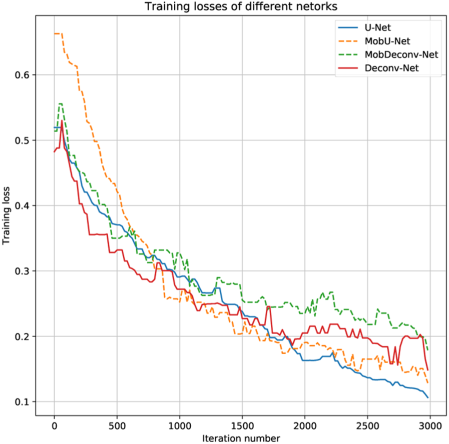
Training losses of different networks.
Figure 8 illustrates the statistic results of the classification accuracy on different models. The test data set was created on Haar algorithm with level-4 compression. U-Net in Figure 8 expresses out-performance compared with other methods, while MobU-Net have better performance than MobDeconv-Net. In summary, the statistic results keeps with the uniformity in Table 3.

Mean and standard deviation of networks accuracy.
To further verify the performance of the four networks, the inference speed of the networks on test data and the peak memory cost is calculated and demonstrated in Table 7. The inference speed is evaluated when the trained model is implemented on a laptop computer with i7 CPU, 4 GB Memory, and integrated GPU.
The results in Table 7 demonstrate that the peak memory cost of the MobU-Net has been greatly reduced compared with the U-Net utilizing standard convolutional layers and the model with uncompressed data set. The two architectures have similar inference speed with stand convolution layers or depthwise convolution layers, while the architecture based on U-Net shows better potential of reducing memory cost by depthwise separable convolutional layers. In summary, the MobU-Net expresses better overall accuracy and recall than the MobDeconv-Net in Level-4 data set, and its memory cost is small enough for the ARM9 processor in ASRTU satellite. In addition, the inference speed of MobU-Net model based on the simulation satisfies the speed requirement of data processing. Thus, the MobU-Net would be selected for the cloud classification in this mission.
Figure 9 illustrates the classification results by MobU-Net combined with Haar wavelet compression algorithm. In Figure 9(d), white areas represents cloud areas that are classified correctly, red area means non-cloud area misclassified as cloud area, and pink area represents cloud area misclassified as non-cloud areas. It is obvious that the major part of the cloud area are distinguished directly while some edge areas and corners with thin cloud is hard to classify.

Cloud-detection results of level-0 and level-4 images. (a) raw image, (b) groundtruth of raw image and white class represents the cloud, (c) level-4 compressed image, and (d) classification result on level-4 image, red and pink represent the misclassification areas.
Conclusion and discussion
The increase of the spatial resolution of RS missions with small size and lightweight proposes more requirements of downlink capability, the on-board detection and classification of the RS images are of great value to improve the downlink efficiency and enhance the performance of the optical imaging system, especially in small satellites with low cost.
A framework of the on-board cloud-detection system is investigated, and the experiment results have demonstrated that MobU-Net network combined with Haar wavelet compression algorithm shows the best performance in general on the SPARCS data set for the ASRTU mission. The experiment results illustrate that the overall accuracy of the MobU-Net can achieve 93.10%, while its maximum memory cost only requires
There are still several aspects left for future improvement. Other data sets should be introduced to testify the algorithms and improve its performance. And careful system engining is required to find the balance between the cost and the efficiency of the data transmission system. Moreover, more strategies that could reduce the model size should be testified and compared.
Footnotes
Handling Editor: ZW Zhong
Declaration of conflicting interests
The author(s) declared no potential conflicts of interest with respect to the research, authorship, and/or publication of this article.
Funding
The author(s) received no financial support for the research, authorship, and/or publication of this article.