
Abstract
The calculation of the dynamic stress of a large and complex welded carbody is the key to the fatigue design and the durability evaluation of the carbody. Adopting the advanced structural stress based on the finite element method, a new finite element transformation method between random loads and dynamic stresses is proposed to be applied in carbody for high-speed trains. The multi-axial random dynamic load spectrums of full-scale carbody are obtained by the vehicle system dynamics method, and the shell finite element model of a full-scale carbody is established. Adopting the concept of a surrogate model, the finite element transformation relationship between the random load and the dynamic structural stress at concerned points is constructed by using multidisciplinary methods to compute the dynamic stress spectrums of concerned points at the welding seam, and dynamic structural stresses are compared and validated through carbody rig-test. The analysis methods of dynamic structural stress are performed systematically for a full-scale welded structure, which provides reference methods for the fatigue durability evaluation of large-scale welded structures.
Keywords
Introduction
The high-speed EMU (Electric Multiple Units) trains adopt a lightweight design and power distributed technology. The structures and loads are different from those of traditional railway vehicles. The carbody is made of aluminum alloy material with extrusion sections, and it is assembled as a whole by the welding process. With the development of technology and the improvement of trains’ running speed, the random loads bearing by the carbody have the characteristics of high-frequency and small-amplitude dominant. The weld of the carbody is easy to fatigue failure. The structural strength and reliability of the carbody are challenged.1–3 In the actual operation process, the carbody is subjected to complex multi-axial alternating loads, and its operational safety is directly related to the safety of passengers. Therefore, the anti-fatigue design and evaluation of welded structures are very important. The critical step in the fatigue durability evaluation of welded structures is to obtain the dynamic stress.
Regarding high-speed trains, many works have been done about the structural design method, the strength assessment method, and welding quality evaluation of railway equipment and other aspects in countries such as Germany, Japan, and so on. All kinds of standards have been worked out and widely used in early bogies and steel carbody structures.4,5 The fatigue strength analysis of carbody is mostly based on the vibration acceleration load in the industry standards, and the fatigue strength is evaluated by Goodman fatigue curve,6,7 or based on S-N curve and fatigue cumulative damage rule to predict its fatigue life under constant or variable amplitude loads.8–11 Luačnin et al. 12 used the UIC (International Union of Railways) standard and the finite element method to analyze the fatigue of a diesel railcar bogie, comparing the fatigue crack location of the bogie in service, and pointed out that it is not accurate to use the standard to determine the dangerous position of fatigue, and fatigue analysis should be carried out according to the stress spectrum which is more in line with the actual condition. The fatigue damage of the high-speed train is mainly caused by the stress cycle that the structure is subjected; the key to evaluate the fatigue reliability is to obtain accurate stress–time history. As for the carbody structure, the actual operating test is the most effective way to obtain the dynamic stress, but it is not realistic for the carbody at the design stage. To evaluate the fatigue life of the carbody at the design stage, it is necessary to use the computer simulation to calculate the load–time history. Then, the random stress–time history of the carbody is obtained by a certain method, which provides the stress data for the fatigue reliability evaluation.
The nominal stress method and hot spot stress method are usually used for the fatigue analysis of welded structures, and the application of the notch stress method has also entered the initial stage at present. The nominal stress analysis method is widely used both at home and abroad to predict the crack initiation life of structures, which is more effective for the low stress and high-cycle fatigue life prediction. Multidisciplinary methods integrate application of the vehicle system dynamics method, the finite element method, the polynomial fitting method, and so on. Lu et al. 13 used multidisciplinary methods to obtain the nominal stress of the carbody and analyzed the dynamic reliability of the carbody. Wu et al. 14 used the shell element and the beam element to perform finite element analysis, obtained the stress–time history of boom girders of a concrete pump truck, and compared it with the stress–time history obtained from the lab test to verify the accuracy of results. Then, the nominal stress method and linear damage cumulative criterion were used to evaluate the fatigue of boom girders. 15 The bogie frame and carbody belong to the typical low stress and high-cycle fatigue problems, so the nominal stress analysis method is widely used to predict the fatigue life, but there are many types of welded joints used in the carbody, so it is very difficult to determine the nominal stress of welded joints in practical calculation. Based on the fatigue failure characteristics of welded structures, Radaj et al. 16 and Hobbacher 17 adopted the hot spot stress analysis method and notch stress analysis method, which effectively eliminated the dispersion of the nominal stress of joints. Nykänen et al. 18 calculated the notch stress range under the constant amplitude load by using the master S-N curve and Miner’s linear cumulative damage rule. Then, the fatigue strength of welded structures under variable amplitude loads was predicted by the notch stress method considering local stress ratio. Leitner et al. 19 utilized a linear-elastic notch stress calculation to investigate the numerical influence on the notch stress based on the fatigue strength assessment of non-welded and welded components. In view of the wheel-rail, some methods of stress fatigue analysis with thermal stress are put forward. Jing and Han 20 explored the impact response of the wheel-rail under the vertical impact force and considered the thermal stress caused by the wheel-rail sliding friction; then, a comprehensive dynamic finite element simulation method based on a three-dimensional (3D) rolling contact model is proposed. However, there are some defects in the hot spot stress method; the literature 21 has pointed out that the stress of the welding seam in IIW (International Institute of Welding) standard is obtained by extrapolation based on the surface stress near the weld toe or surface stress values. It is an empirical treatment method and cannot be reasonably explained by the mechanics theory, and some researches have pointed out that the stress extrapolation method is very sensitive to the mesh size at the weld toe and the stress value obtained by the extrapolation of models with different mesh sizes were very inconsistent. Furthermore, the uncertainty in fatigue evaluation is increased, and the reliability of fatigue analysis results is reduced. Dong and colleagues22–26 from the University of Michigan presented the structural stress method with mesh insensitivity, which can effectively analyze the fatigue strength of welded structures. Nominal stresses of welded joints were corrected by this method, and the dispersion of fatigue data was greatly eliminated, thus a unified master S-N curve was obtained. This method has become a popular method for fatigue analysis of the carbody. It is also widely used in automobiles. Zhao et al. 27 used a torsion beam rear axle from a sport utility vehicle as an example. According to the four different damage accumulation rules, the fatigue lives were calculated with structural stresses at failure positions, and the calculated lives were compared with the experimental results, which resulted in the proposal of an improved Miner rule.
This article takes a welded aluminum alloy carbody of the high-speed train as a research object. First, load spectrums of the carbody bearing positions are obtained by establishing a system dynamics model of the carbody, and a full-scale finite element shell model of the carbody is established. Then, the load conditions design of the carbody is carried out by using the polynomial fitting and Box–Behnken matrix design. Based on the inertial release method, the stress distribution of the welding seam under load conditions is calculated, and thus the relation function between random loads and structural stresses at concerned points is constructed. Finally, the dynamic structural stress–time history is obtained and validated.
Dynamic structural stress analysis theory of welded structures
Comparison of traditional stress analysis methods
The different stress parameters used in the welded structure analysis represent the different stress concentration types shown in Table 1.
Nominal stress method: If the stress at a fatigue prone location cannot be determined with a mesh insensitivity in using finite element methods, finite element–based fatigue evaluation cannot be carried out in any meaningful manner. This is the reason that in the welding seam classification method in BS 7608, the nominal stress definitions in the context of material strength is used in presenting the fatigue test data in the form of S-N curves. For different joint types and loading modes, different fatigue S-N curves must be used. The welding seam classification method as descried in the procedures such as BS 7608 is not intended to be used for design by analysis purpose using finite element methods since the design curves in BS 7608 can only be used when nominal stresses for a given joint class is available in the context of materials strength. In analyzing realistic welded components, such nominal stress definitions can be difficult to define.
The hot spot stress method: The hot spot stress method described in the IIW standard mainly obtains the hot spot stress result by extrapolating the reference point stress near the weld toe point to the hot spot. The precondition for this method is to assume the location of crack initiation at the weld toe. The hot spot stress method in the IIW standard is suitable for fatigue life prediction of the weld toe. And the IIW standard can also evaluate the fatigue life of weld root by extrapolation procedures. 28 Due to the lack of a mechanics basis in relating surface stresses or extrapolated stresses to the stress state at the weld toe, these methods can only be viewed as a series of empirical stress extrapolation procedures. In determining the hot spot stress at the weld toe, most of extrapolation programs is affected by the sensitivity of mesh size and element type. The above regarding extrapolation-based hot spot stresses that the lack of a consistent finite element–based stress calculation procedure is one major problem shared by the new codified procedures.
Notch stress method: From the calculation method of notch stress, it can be seen that the calculation has very strict requirements for the mesh precision of the finite element model. The fatigue life prediction by this method is more complicated than the nominal stress method and hot spot stress method in the finite element modeling stage. Therefore, this method is rarely used in the current fatigue analysis literature.
Different types of the stress concentration in fatigue analysis methods.

Based on the above reasons, this article uses the structural stress method with the mesh insensitivity. This method can effectively analyze the fatigue strength of welded structures, and it is also included in the American Society of Mechanical Engineers (Section VIII, Rules for Construction of Pressure Vessels, Division 2).
Structural stress method
The main fatigue stress analysis methods include the nominal stress method, the hot spot stress method, and the notch stress method. The difference of several methods is mainly due to the description of stress parameters corresponding to the stress concentration effects. The structural stress method is mainly aimed at the local stress and weld location of welded structures. The fatigue stress evaluation is performed using the structural stress method because this method is applied in the calculation of large-scale structures with less mesh sensitivity. Other stresses (e.g. equivalent stress, maximum principal stress, etc.) have serious mesh sensitivity. And in these stress methods, the control of the mesh greatly increases the cost of computation. The mesh size is sensitive to the stress results, which affects the accuracy of the fatigue strength evaluation.
The true stress of the weld toe section includes three parts:

Structural stress distribution of the weld toe section.
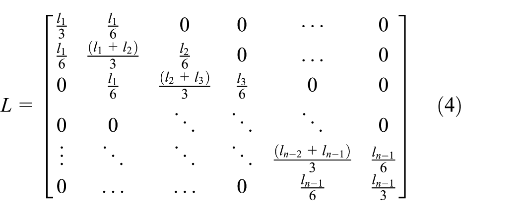
The structural stress method takes the nodal force as the basic parameter, according to the energy conservation law, and then, transfers the nodal force to the linear force on the element boundary

where F is the nodal force vector, L is the transformation matrix, and f is the linear force on the element boundary.
Nodal force expressions on the local coordinate system


where
The diagram of the relation between the linear load and nodal load is shown in Figure 2. In Figure 2,

The relationship between the nodal force (the nodal moment) and the linear force (the linear moment).
The equation can be established by the relationship shown in Figure 2


and
Similarly, the linear moment and the nodal moment can be established by the same relationship and calculated as follows


The stress on the element surface can be deduced by the linear force calculated in equation (1). Therefore, the structural stress at any point on the welding seam can be calculated by the distributed load on the welding seam

where
Dynamic structural stress calculation method
When calculating the fatigue damage of carbody, the dynamic structural stress should be obtained first. The methods of obtaining the dynamic structural stress are the analytic method and finite element method. For the welded carbody, the finite element numerical simulation method is usually used at present. Based on the finite element analysis, the fatigue stress calculation methods include the quasi-static method, the transient analysis method, and polynomial fitting method. 29 In the quasi-static method, without considering the elastic vibration, the quality, and inertia of structural components, the main idea is to calculate the elastic stress–strain state caused by the unit static load under the same position and direction at any time, and then, load–time histories are obtained by corresponding measurement or dynamic simulation. This method is suitable for engineering structure with the loading frequency far less than the structural natural frequency; however, with the increase of running speed, the external loading frequency range of the vehicle expands gradually, and the quasi-static method is not applicable to the conversion of stress–time history. The transient analysis method can obtain stress results with high accuracy, but this method requires significant computing resources. This method is difficult to perform in a stress solution with complex loads and long duration. 30 Therefore, this article does not use these methods. The surrogate model constructed by the polynomial fitting method can be used to replace the finite element model of the complex structure to calculate the dynamic stress of the complex structure.
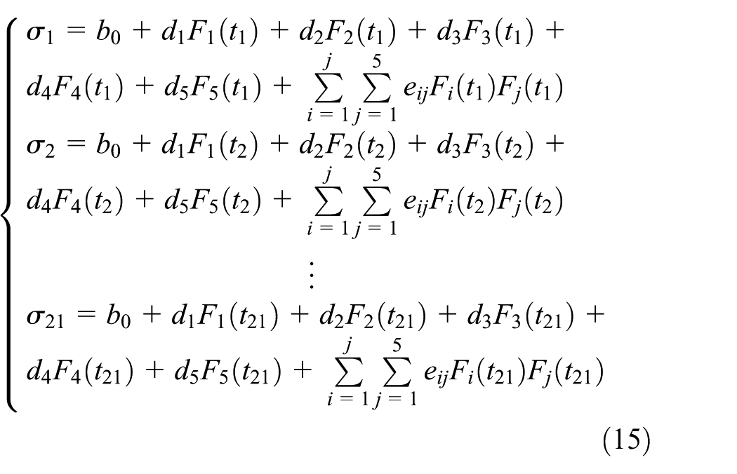
The complex structure may lead to a nonlinear constitutive relation between the structural stresses and external loads. Therefore, it is necessary to select the quadratic polynomial with a cross-term to establish the relation function (see equation (12))

where
Before the polynomial fitting function is established, a series of input variable values are sampled to form a number of test points. The output response is obtained by analyzing the real model, and then, the unknown functions of the fitted functions are obtained. The most commonly used experimental design method in polynomial fitting is the Box–Behnken matrix method, which is a second-order experimental design method based on the three levels. Since each input variable only needs to design three levels, it is more efficient than the other methods.
Dynamic structural stress calculation of the carbody
The above structural stress method is applied to the carbody, and then, the dynamic structural stress of the carbody is analyzed and calculated. First, the multi-body system dynamics is used to obtain the random load–time history, and the load–time history is transformed into the stress–time history. That is, the dynamic structural stress of the carbody is obtained. For the complex welded carbody, the structural dynamic stress is effectively calculated by a new finite element transformation method.
Load spectrum calculation of the carbody
The vehicle system is mainly composed of the wheel, the frame, the beam, the carbody, the primary and secondary suspensions, the shock absorber, and so on. It is a nonlinear vibration system with multiple degrees of freedom. 31 In this article, the dynamics simulation software is used to establish the vehicle system dynamics model (see Figure 3). The model considers the wheel, the frame, the beam, and carbody as the rigid body. The axle spring, the air spring, the anti-yaw vibration absorber, and the lateral/longitudinal vibration absorber are treated as force elements. To be closer to the actual operation, the nonlinear factors in the system are considered, including the geometric nonlinearity of wheel-rail contact, the nonlinearity of wheel-rail creep force, the nonlinearity of suspension system parameters, and so on. The measured track spectrum of the Beijing–Tianjin intercity rail is adopted in the simulation.

Vehicle system dynamics model.
Dynamic reliability analysis of the carbody must determine the load–time history. According to the actual railway condition and operating speed, two calculation conditions are selected: 275 km/h variable speed stage and 350 km/h constant speed stage, and the vertical load–time history of the air spring is calculated. Then, with 200–350 km/h acceleration stage, 350 km/h constant speed stage, and 350–200 km/h deceleration stage as calculation conditions, and the longitudinal load–time history of the coupler is calculated. Therefore, the vertical dynamic load on the air spring and the longitudinal force at the coupler are the loads considered in this article. The calculated load–time history has experienced a total of 600 s, 0–200 s is the acceleration condition, 200–400 s is the constant speed condition, and 400–600 s is the deceleration condition (see Figures 4–6).

The vertical load–time history for different sides air spring on first end: (a) left side and (b) right side.

The vertical load–time history for different sides air spring on second end: (a) left side and (b) right side.

The longitudinal load–time history.
As shown in Figures 4–6, the maximum load variation range is 18 kN, which is consistent with results of tested vehicle operational loads.
Establishment of the carbody finite element model
For the calculation of the carbody finite element analysis, modeling is the key to get the accuracy results. The aluminum alloy grade of the carbody analyzed in this article is A7N01. And mechanical properties for the aluminum alloy are as follows: Young’s modulus is 6.90 × 10⁴ MPa, the yield strength is 295 MPa, the Poisson ratio is 0.29, and the density is 2.70 × 10³ kg/m3. And the welding process is MIG (Metal Inert-gas Welding). The high-speed train is welded by aluminum alloy hollow extrusion sheet profile. The carbody is a typical thin plate structure with a thickness of 3, 4, 6 mm, and so on. Relative to the thin plate length of 25,000 mm and width 35,000 mm, the thickness is much smaller than its length and width. Therefore, based on the Kirchoff plate shell theory, it is established that the finite element model of the carbody is able to meet the requirements of the solution with accuracy. The finite element model should be established using the shell element. Taking into account that the carbody in service will be subject to a vertical bending load, longitudinal tensile load, and compression load, the use of the shell element can effectively simulate the bending and tensile mechanical properties of the shell. Then, the shell element (first order element) is selected to carry out the meshing of the carbody. The overall finite element model of the carbody is shown in Figure 7. The carbody model consists of 1,215,440 elements and 1,068,972 nodes.

Finite element model of the aluminum alloy carbody.
Before the subsequent finite element analysis, the mesh convergence of the carbody finite element model is checked to eliminate the error caused by the mesh factor. Take a long welding seam on the sidewall (see Figure 8(a)) as the object of inspection; three discrete models with different mesh sizes (50, 30, and 15 mm) are established, and one time gravity acceleration load is applied. Then, the structural stress calculation is carried out by extracting the nodal force, nodal moment, and other data of the element node of the welding seam. As shown in Figure 8(b), structural stress results are basically consistent. The structural stress of the welding seam with the element size of 15 mm is selected as the standard result. Calculation of the maximum relative error of the structural stress of the welding seam with the element size of 30 mm is 0.7%, and the maximum relative error of the structural stress with the element size of 50 mm is 2.3%. These results indicate that the structural stress method is less sensitive to the mesh in the calculation of carbody.
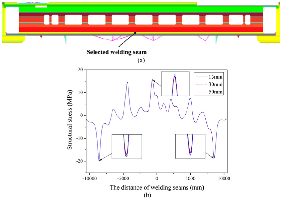
Structural stress results of the carbody welding seam: (a) the selected welding seam and (b) structural stress results.
The carbody model is discretized by the shell element. Because of the simplification of the welding seam, the joint shape has not been established for the butt joint and the lap joint. Although the calculated results are still insensitive to the mesh, the geometric stress concentration effect is not included in the results, so the structural stress is closer to the nominal stress. Since the structural stress method is used to predict the fatigue life of carbody, it is necessary to modify the calculated structural stress by multiplying the correction factor (see equation (13)); otherwise, the calculated structural stress results are unsafe

where
The correction factors for two types of joints are calculated as follows:
Butt joint: According to the butt joint form of the actual carbody, the joint finite element models of element dimensions 4 mm, 2 mm, and 1 mm (as shown in Figure 9, 0.5 t, 0.25 t, and 0.125 t, t is joint thickness and equal to 8 mm) are established. The element is set as the plane strain, and the stress concentration factor of the weld toe in the middle of welding seam is to be calculated. The results are shown in Figure 9(a). It can be seen that the concentration factors calculated by three different element dimensions are basically the same, with a maximum value of 1.34. For the sake of safety, the correction factor of the butt joint should be selected as 1.35 in the life prediction to ensure the reliability of the life.
Lap joint: The lap joint in the carbody mainly appears in the sidewall and underframe, in which the side beams of underframe and floor are connected with a long lap welding seam. In the same manner, three mesh sizes of lap joints are established. The calculated correction factors are shown in Figure 9(b), with a maximum value of 3.61. In the subsequent calculations,

Correction factors of the butt joint/lap joint under different mesh sizes: (a) butt joint and (b) lap joint.
The calculation procedure of the polynomial fitting method
Establishment of the carbody polynomial fitting formula
Since main loads of the high-speed train are the loads at the air spring and the coupler, and it is denoted as

where

The load position of the carbody.
Determination of design conditions and finite element analysis
The input loads are vertical dynamic loads of four air spring parts and longitudinal dynamic loads of the coupler. Considering that the maximum value of fluctuating variation of the load–time history is 116.62 kN and the minimum value is 98.93 kN, three levels of the experiment were 98.93, 108.49, and 116.62 kN, respectively. And the maximum value of fluctuating variation of the longitudinal load–time history is 39.32 kN, and the minimum value is −36 kN, so three levels of experiment were −36,0.93, and 39.32 kN. Using the Box–Behnken matrix to design the five factors, the three levels test method can determine 41 test points, and each test point corresponds to a load condition. Box–Behnken matrix design
32
is the most commonly used orthogonal test design method in polynomial fitting. Box–Behnken matrix design is a three-level second-order test design method. Compared with other methods, Box–Behnken matrix design is more efficient because only three levels need to be designed for each test variable. The total number of tests determined by Box–Behnken matrix design is
In the finite element calculation, the stress responses are calculated by applying different loads at the air spring and the coupler. Because the inertia relief method being applied to virtual constraints can eliminate stiffness matrix singularity of the carbody finite element model, the inertia relief method is used to calculate the stress distribution of the carbody finite element model under 21 conditions, and get finite element results under different conditions. The basic principle of the inertia release method is to balance the external force with the structural inertia (mass) force and construct the self-balancing force system in the calculation process. To prevent the displacement of the rigid body, it is necessary to set up the virtual constraint to constrain the six-degrees-of-freedom of the carbody.
Definition of the welding seam and calculation of the structural stress
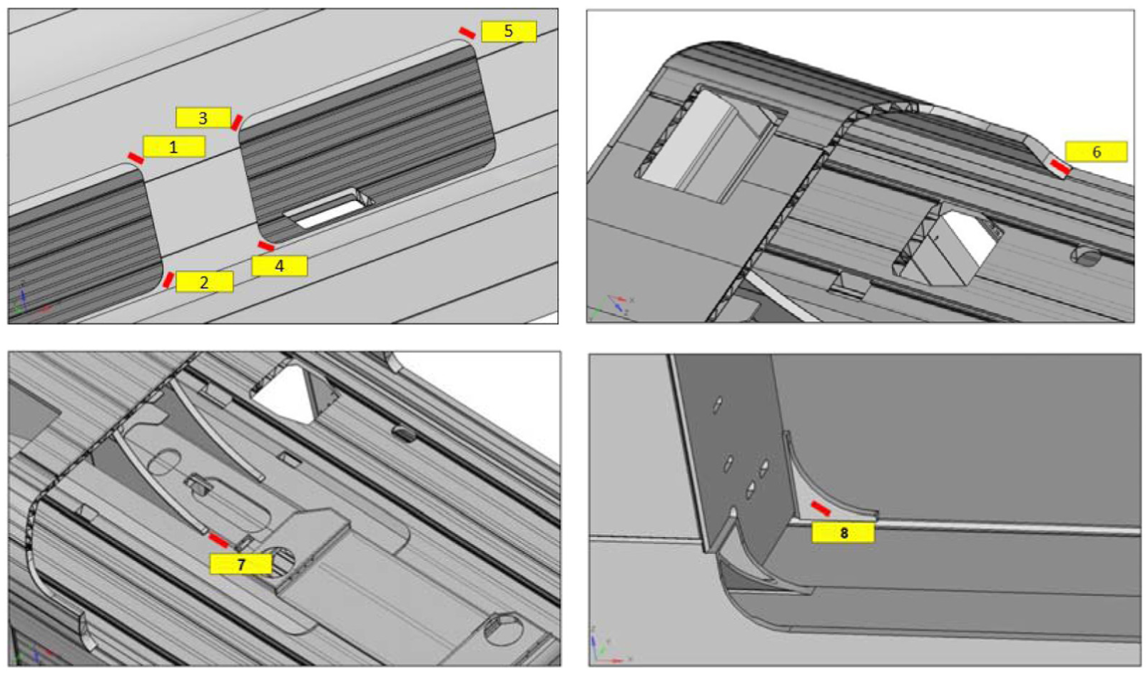
Before the structural stress calculation is carried out, the location of the welding seam that needs to be analyzed is determined. In the calculation, the vertical random load of the air spring and the longitudinal random load of the coupler as the loads to be taken into account, so loads on the end wall and the end of the underframe are large. Through the above analysis, 10 welding seams are distributed in the sidewall and the underframe floor and the top of carbody. Then, the structural stress distributions and stress ranges of selected welding seams are analyzed, and the structural stress distributions under design conditions are obtained.
The nodal force and nodal moment results of the typical welding seam on the carbody are extracted by the structural stress calculation method. The structural stress distribution of each welding seam under 21 conditions is obtained by using the homemade program. That is, the structural stress

The selected concerned points of the carbody welding seams.
Through the outputs of
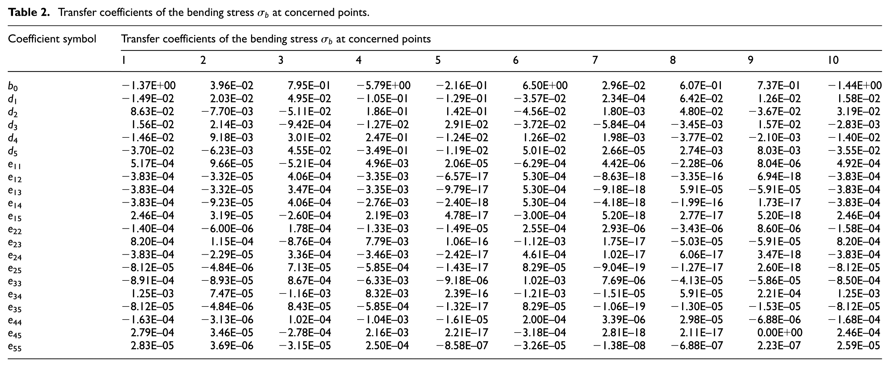
Calculate the transfer coefficients of concerned points
The load data under different conditions and data of
Transfer coefficients of the bending stress
Transfer coefficients of the membrane stress

Fitting results of the dynamic stress–time history at concerned points
Bring the transfer coefficients and load–time histories into equation (14). Then, construct the polynomial fitting relationship between the input loads and stresses of concerned points, and the dynamic structural stresses of concerned points are calculated. There are 21 polynomial fitting coefficients in equation (14), so it is necessary to determine 21 independent equations of loads and responses to establish the quadratic polynomial equations. The undetermined coefficients obtained by solving the equations are used for transformation of the load spectrum into the dynamic structural stress, and stress–time histories of fatigue concerned points are obtained. Figure 12 shows the structural stress histories of the concerned point 5 and point 8. It can be seen from Figure 12 that the structural stress variation range of concerned point 5 is 9.52 MPa and its mean value is 48.49 MPa, and the structural stress variation range of concerned point 8 is 2.75 MPa and its mean value is 61.11 MPa.

The structural stress–time history of concerned points: (a) concerned point 5 and (b) concerned point 8.
Verification of the dynamic stress results
Based on the structural stress method to predict fatigue life of the carbody, the fatigue test is carried out on the carbody to compare the calculated results. And the lab test adopts the dynamic test, the loading frequency is 4 Hz. The fatigue test rig is shown in Figure 13.

The fatigue test rig of the high-speed train aluminum alloy carbody: (a) physical photo and (b) test rig diagram.
Before the dynamic stress test of the carbody, the load conditions must be determined. According to the standard of “EN 12663: Railway Applications—Structural Requirements of Railway Vehicle Bodies,” the external loads that cause fatigue damage of the carbody mainly include the longitudinal, vertical, and lateral loads of the track caused by the train traction and brake, and the vertical and lateral loads caused by the track irregularity.
According to EN 12663, the dynamic stress test of the carbody is carried out under the longitudinal, vertical, and lateral loads. The conditions are shown in Table 4.
The dynamic stress test conditions of the carbody (unit: m/s2).

According to the specified conditions, the dynamic stresses of the carbody on the side wall and underframe are tested, and the influence of loads in three directions on fatigue strength of the carbody is analyzed.
The carbody simulates the vertical load distribution of the real vehicle by applying the weight block. The vertical forces of the air spring, and the lateral and longitudinal forces of the central pin are dynamically loaded by the six-degrees-of-freedom platform (see Figure 13(b)). The test bench mainly consists of two six-degrees-of-freedom loading platforms, including two vertical actuators, two longitudinal actuators, and one transverse actuator, which can be used to load the six directions of the carbody.
The strain gauge should be set up before the test to determine the stress test position on the carbody. The position of the strain gauge is mainly determined by the strength weak point in strength analysis of the carbody. The window corners of the side wall in the vertical condition, the end of underframe in the longitudinal tension, and compression condition are the concerned location for the designer. Therefore, the locations of the strain gauges are mainly concentrated on the window corners and the slave board of the underframe (see Figure 14).
Test positions of strain gauges.
In the signal acquisition, the signal variation is obtained through abnormal signal processing, filtering processing, the omission of the invalid amplitude, and the processing of removing zero drift. Through the conversion and statistics of stresses, the stress range variation of each strain gauge is obtained. According to the fatigue damage theory, the fatigue failure is easy to occur in the location with a larger stress range. Based on this, the impact of the three-way dynamic load on fatigue strength of the carbody is analyzed.
From Table 5, it can be seen that the stresses corresponding to the longitudinal and lateral loads are very small. In general, the vertical load dominates the stress at concerned points. The vertical load range at the air spring position is about 30 kN under this condition, and the maximum variation range of the load spectrum used in fatigue analysis is about 18 kN. Therefore, the measured stress range is the transformed data corresponding to the calculated results (see Table 5). Since the calculated structural stress considers the vertical load and longitudinal load, the measured vertical stress and longitudinal stress must be superimposed and then compared with the calculated structural stress range (see equation (16))

where
The range of stress variation under dynamic load conditions in each position.

And the maximum dynamic stress range of the window corner is 10.023 MPa in the vertical and longitudinal dynamic load test, and the maximum structural stress range of the window corner is 9.517 MPa in the calculation. Therefore, the relative error between the measured dynamic stress range and the calculated dynamic stress range is 5.05%. The reasons for the difference between the calculated stress range and the measured stress range are as follows: (1) A large amount of structural details are neglected during modeling, so the calculated stress distribution is more uniform than the measured stress distribution. (2) The random load is used in calculation, and the constant amplitude load is applied in the lab test. The difference in load results causes a large difference in local stress re-distribution. (3) In the lab test, the quality of the suspension equipment is distributed by evenly placing sandbags in the carbody. And in the calculation process, the suspension equipment adopts a local-rigid connection. (4) The measured stress is the measured uniaxial (longitudinal and vertical) stress separately, and the stress values are linearly superposed. However, the calculated stress results under the longitudinal and vertical loads are simultaneously considered in the finite element analysis. The above reasons lead to differences in stress results. The relative errors between the calculated results and measured results are less than 6.50%, and the calculated structural stress ranges are effective.
Summary and conclusions
In this study, an aluminum alloy welded carbody for high-speed trains is taken as the research object, and the finite element transformation method of dynamic structural stress was proposed. First, the finite element model and multi-body system dynamics model of the carbody were established, and the vertical and longitudinal load spectrums of the carbody were calculated. The polynomial fitting method and orthogonal experimental design were used to achieve the transformation from the load spectrum to the dynamic structure stress. Finally, the validity of dynamic structural stress results obtained in this article was verified, which provides the basis for calculating the time history of dynamic structural stress of the welded structures. The conclusions are as follows.
In the mesh convergence analysis, the structural stress results are calculated by the finite element model of carbody with different mesh sizes (50, 30, and 15 mm). The results show that the structural stress method is less sensitive to the mesh in the calculation of the carbody, and the results obtained by a coarser finite element model still have some accuracy; the fatigue analysis of carbody by means of structural stress effectively reduces computational cost.
According to the theory of structural stress, the stress of welded structures calculated by shell model neglects the geometrical stress concentration effect at welded joints. Therefore, it is necessary to use the correction coefficient to correct the structural stress; calculating the typical welded joint model, it can be seen that the correction factor of the butt joint is 1.35, and the correction factor of the lap joint is 3.65.
The Box–Behnken matrix design and polynomial fitting methods are used to establish the surrogate model of carbody, which can effectively transform the load spectrum into the dynamic structural stress–time history. When the simulation results are compared with the measured dynamic stresses, the effectiveness of dynamic stress results in the fatigue analysis is verified.
Footnotes
Appendix 1
Handling Editor: Luca Furgani
Declaration of conflicting interests
The author(s) declared no potential conflicts of interest with respect to the research, authorship, and/or publication of this article.
Funding
The author(s) disclosed receipt of the following financial support for the research, authorship, and/or publication of this article: This research was supported by the National Natural Science Foundation of China (Grant No. 51275428, U1334206) and Sichuan International Scientific and Technological Cooperation and Exchange Research Project (Grant No. 2018HH0072).