
Abstract
The fatigue assessments for boom girders of a concrete pump truck, which is typically a welded box girder structure, were investigated in this study. Finite element analysis were conducted using shell and beam elements to obtain the stress histories of the boom girders. Field tests were performed to verify the finite element model. Then, the loading spectrum was developed using the rain-flow counting method. The fatigue assessments for the boom girders were evaluated using the nominal stress method and Miners cumulative damage rule based on the International Institute of Welding recommendation. It is found that some critical locations of the boom girder were at risk for fatigue failure. To overcome this problem, it is suggested to add diaphragms to boom girders.
Keywords
Introduction
Construction machinery is widely used in construction engineering because of its characteristics of high productivity and low cost. A concrete pump truck is one type of construction machinery that is used to pump concrete to a desired location. 1 The main components of the concrete pump truck are typically welded box girder structure. Generally, welding causes local stress concentrations and other types of defects. These welded components subjected to fluctuating loads may experience serious fatigue failure and catastrophic results. To avoid the premature fatigue failure of these welded components, a fatigue assessment should be performed to ensure that these welded components resist fatigue failure for a predicted service life.
Principal factors affecting the fatigue life of welded components are the range of stress that the component is expected to experience and the number of cycles. Caglayan et al. 2 presented fatigue results for welded crane runway girders. Finite element (FE) and quasi-static load tests were conducted to acquire the load spectrum of crane runway girders. The remaining fatigue life of the crane runway girders was evaluated based on the AASHTO specification. Wang et al. 3 presented a fatigue assessment of fixed offshore platforms. Li et al. 4 proposed a new fatigue life analysis method based on six-sigma robust optimization to optimize the weight of collector head support. The reason for fatigue failure of a rear axle housing prototype that is used in the heavy commercial vehicles was investigated by Topaç et al. 5 Detailed finite element analyses (FEA) were performed to estimate the stress distributions for the stress concentration regions. The fatigue analysis were performed using an estimated S–N curve for the housing material. A practical solution of redesigning the banjo transition area and increasing the thickness of the reinforcement ring has been proposed to increase the fatigue life. The fatigue life of a railway rail subjected to welding residual and contact stresses was presented by Lee et al. 6 The FE method was used to predict the residual stress. The contact stress when a wheel rolled over a weld was calculated based on the elastic elliptical contact model. Then, the fatigue damage was evaluated by combining with the residual stress and contact stress. Yin et al.7,8 presented research work for assessing the fatigue life of heavy mining equipment. In their study, the stress histories of a boom were obtained from field tests based on field operating conditions. Then, the load spectrum was developed from tests results using the rain-flow counting method. Furthermore, the fatigue life of a boom was evaluated using the fatigue crack growth model. Goyal et al. 9 proposed a robust, sufficiently accurate, and efficient stress analysis method for fatigue life estimation of welded structures based on three-dimensional (3D) FE coarse mesh models. Chen et al. 10 used the equal strength design of rim to reduce the weight of the wheel based on stress and fatigue analysis. Łukaszewicz 11 presented a method of assessing fatigue strength for a body in conditions of cyclical tension and torsion. Based on International Institute of Welding (IIW) recommendation, the fatigue life of a welded A-stay beam structure used in construction machinery was investigated by Pettersson and Barsoum. 12 The nominal stress, structural hot spot stress, effective notch stress, and linear elastic fracture mechanics (LEFM) were used to estimate the fatigue life of the beam structure. Rother and Rudolph provided some discussion on the analysis methods for fatigue assessment of a welded structure and recommended a hierarchical two-step procedure for the fatigue assessment of large welded structures. Fang et al.13,14 has used the strain-life method for fatigue life assessment of a truck cab. Furthermore, structural optimization for the fatigue durability was conducted to improve safety and performance of the truck cab with minimum cost. Lei et al. 15 and Li et al. 16 investigated fatigue issues of boom structures of concrete pump trucks. The load spectrum of boom structures was obtained from tests and FEA. Furthermore, fatigue life was assessed using the MSC Fatigue and Ncode DesignLife software. Fatigue behavior of very high strength (VHS) circular steel tube to plate T-joints under in-plane bending was given by Jiao et al. 17
In this study, stress histories were acquired by FEA and filed tests. Based on the results, load spectrum was developed using the rain-flow counting method. Furthermore, fatigue damage assessments of the boom system were conducted by the linear damage accumulation theory.
Investigated component
The object investigated in this study is a boom system of a concrete pump truck. The main function of the boom system is to adjust the end of the boom system by unfolding the boom system. The boom system subjected to cycled loading may lead to fatigue cracking near the welds, which results fatigue failure of the boom system. A failure of this component may lead to loss of production and expensive secondary damages.
The boom system consists of five box girders, four sets of connecting rods, and five sets of cylinders shown in Figure 1. Different cross sections are used in the five box girders. The material used is high yield strength steel WELDOX960 as specified in the EN standard. 18 Its mechanical properties are listed in Table 1. The box girder lengths vary between 6 and 10 m. Box girder heights vary between 220 and 630 mm with flange widths between 158 and 520 mm. Flange and web thicknesses vary from 4 to 12 mm. Types of boom girders are given in Figure 2. Hammer peening is used in the welding process to introduce beneficial compressible residual stresses.
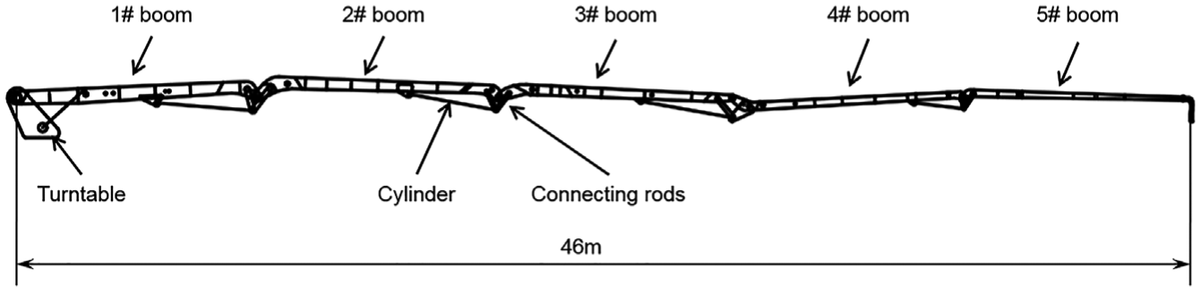
Boom system.
Mechanical properties of WELDOX960.


Types of boom girders (mm).
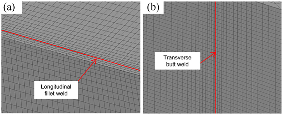
During the pumping operation, the boom system unfolds by the cylinders and rotates by the turntable. So, the end of the boom system can adjust to the desired location. The typical loading of the boom system consists of the friction of the concrete and the self-weight of the boom system. Two typical types of welds of the boom system are given in Figure 3. Longitudinal fillet weld is used between the flange plate and the web plate. Transverse butt weld is used in the conjunction of the two web plates and the two flange plates.

Critical locations of the 1# boom girder.
In this study, the fatigue life of the welds of the boom girder is investigated. First, FE model of the boom system is built using the commercial software Abaqus, and the stress histories are computed through the FEA. Second, field tests are carried out on the concrete pump truck to verify the FE models. Finally, the fatigue life of the boom girders is calculated based on the IIW recommendation.
FEA
Detailed FE models of boom system were built using commercial software Abaqus. The boom girders essentially consists of sets of thin walled shells, which meshed using shell elements S4 and S3. The connecting rods, which similar to boom girders, were meshed using shell elements S4 and S3 too. The cylinders and the pins were meshed using beam element B31. To save computational time, the contact between the pins and boom girders were modeled using the coupling constraints. The FE model of boom system is shown in Figure 4. Typical mesh styles near the welds are shown in Figure 5.

Finite element models: (a) 1# boom and 2# boom and (b) the coupling constraints and pin elements.
Typical mesh styles for (a) longitudinal fillet weld and (b) transverse butt weld.
The working conditions are different as the boom girders at different angles. In this study, six typical working conditions of the boom system which are most used in construction engineering are selected to analyze.
15
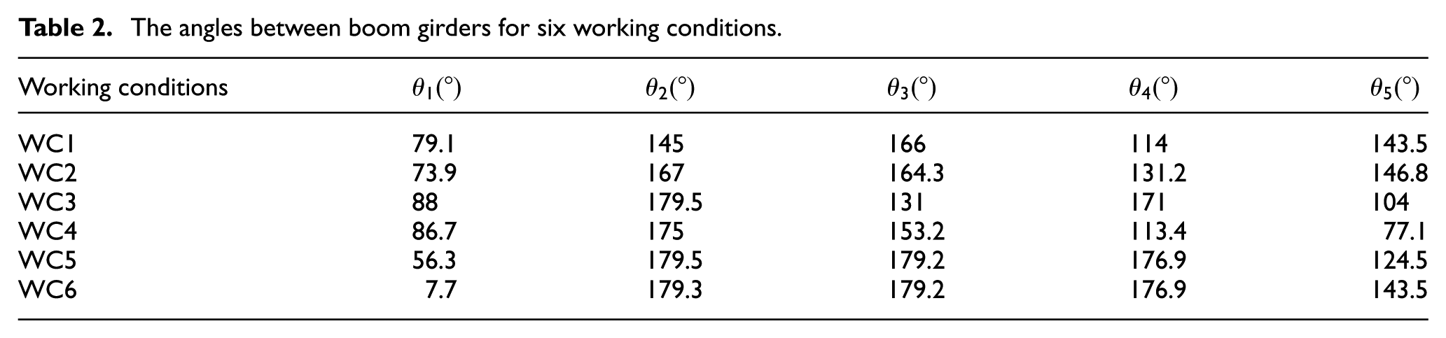
These working conditions (WC1, WC2, …, WC6) are shown in Figure 6. The angles between five boom girders for six working conditions are listed in Table 2, where
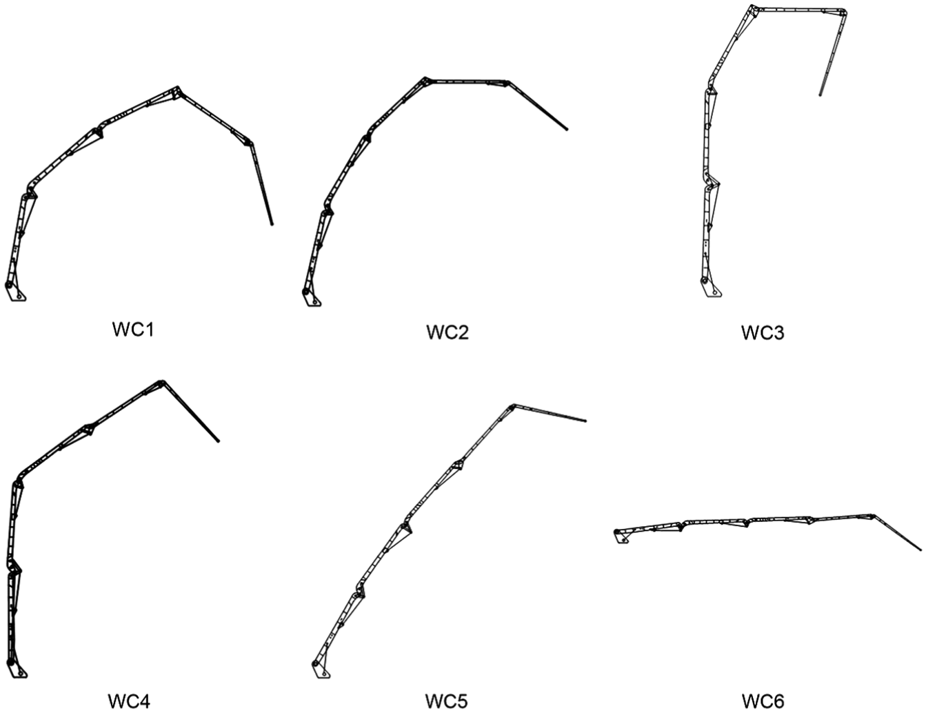
Six working conditions of boom system.
The angles between boom girders for six working conditions.

Stress plots for (a) longitudinal fillet weld and (b) transverse butt weld.
Model verification
To verify the stress histories obtained from FEA, field tests were performed on a concrete pump truck. The field tests were performed on the construction site as shown in Figure 8. Stress histories from field tests were compared with results from the FEA. To measure the stress histories of the boom structures, strain gauges were mounted on the boom girders. BAB Series Mid-Temp. Strain gauges, which manufactured by the ZEMIC (Zhonghang Electronic Measuring Instruments Co., Ltd), were used to measure the stress histories of the boom girders. There were total 90 sets of strain gauges mounted on the five boom girders. Take 1# boom as an example, the orientation and location of the strain gauges are given in Figure 9. The strain histories of each operating condition were measured during field tests. For each operating condition, 2-h stress measurements were performed on the boom girders. While the field tests were performed on different construction sites, the loading sequence did not account in the stress histories results. All measured data were collected at a rate of 150 readings per second using a portable computer.

Examples of field tests: (a) WC5 and (b) WC4.

Strain gauge arrangements for 1# boom girder.
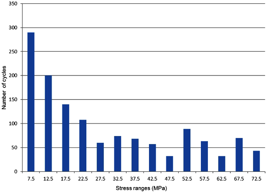
Generally, the measured strains included high-frequency electronic noise. Therefore, the measured strain data were filtered to eliminate the electronic noise through a low-pass finite impulse response (FIR) filter. 19 The high-frequency components of the measured strain data were attenuated and transformed to stress data. We compared the results of FEA and field tests of the five boom girder. The good agreements were found, which indicated that the FEA results can be used for prediction of fatigue life. A sample of the stress histories and stress histogram of the 1# boom girder is shown in Figure 10.
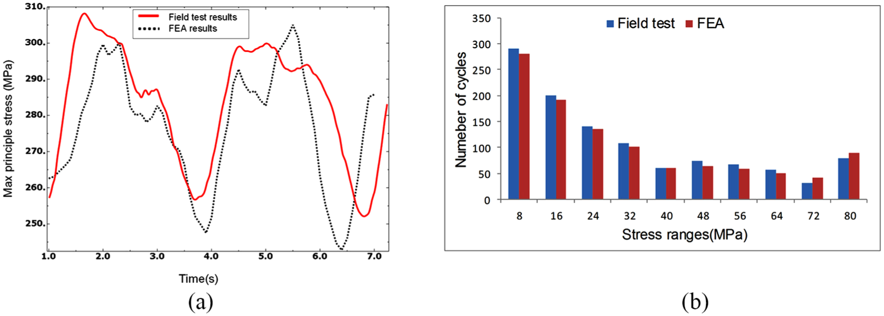
Comparison of the results of field tests and FEA for 1# boom girder: (a) stress histories and (b) stress histogram.
Prediction of fatigue life
Load spectrum
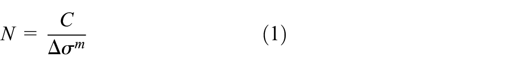
To predict the fatigue life of the boom girders, the load spectrum must be constructed based on the stress histories. First, the stress histories of six typical working conditions were obtained by the FEA. Second, the load spectrum of each working condition was constructed using the rain-flow counting method.20,21 It should be noted that the loading sequence did not account for the load spectrum. Stress ranges less than 10% of the endurance strength were neglected in the calculations because these stress ranges are small and would lead to negligible fatigue damage.
To construct the real load spectrum of the boom structures, the service time of each working condition was counted. Then, the proportion of each operational conditions service time was calculated from the results. The load spectrum of the boom structures was constructed by combining the six typical load spectra. The constructed load spectrum for a 1-h period for the 1# boom structure is shown in Figures 11 and 12.

Stress histogram for longitudinal fillet weld of 1# boom girder (1 h).
Stress histogram for transverse butt weld of 1# boom girder (1 h).
Nominal stress method
According to the IIW recommendation,22,23 the nominal stress is defined as the stress calculated in the sectional area under consideration, disregarding the local stress raising effects of the welded joint. Nonetheless, the effects of the macro-geometric features of the component and stress field in the vicinity of the concentrated loads must be included in the nominal stress. Therefore, the spot of estimating the nominal stress should be apart from the stress concentration area in both the analysis and field measurement. It is recommended to use the stress at a spot that is 1 or 1.5 times the wall thickness apart from the weld toe as the nominal stress. In this study, the nominal stress is assumed to be the stress at a spot 1.5 times the wall thickness apart from the welded toe. The fatigue strength curves can be written as6,24
where N is the number of cycles permitted for
For variable amplitude loading, it is recommend that the stresses below the fatigue limit must be included in the cumulative damage calculation related to welded joints. The modified

Modified fatigue
Because the fatigue classes are developed from laboratory samples, the true fatigue class,

where
For complex two-dimensional (2D) or 3D welded components, the stress ratio factor is
Constants of the fatigue strength

Based on Miner’s rule, the damage increase in each stress range is taken into account, and the fatigue damage can be expressed as25,26

where D is the damage sum,

where
The fatigue life of details of the boom structure can be estimated as follows. First, the fatigue class of a detail should be determined according to the IIW recommendation. Then, the accumulated damage
where
Fatigue life prediction of the weld details of the boom structure
All the weld details of five boom girders can be classified using the nominal stress concept into fatigue class 216 and fatigue class 323 represented by

Classification of the welded details. 22
Taking the 1# boom girder as an example, fatigue life evaluation of critical locations in 1# boom girder by taking histograms into account are summarized below.
Longitudinal fillet weld of 1# boom girder is an example of the detail of

In this study, the critical damage value is set to 0.75, the fatigue life of the longitudinal fillet weld detail was calculated as follows

The designed service life of the concrete pump truck is 6000 h, which is provided by the manufacturer. Thus, the critical location of longitudinal fillet weld of 1# boom is at risk of fatigue failure.
Transverse butt weld of 1# boom girder is an example of the detail of

In this study, the critical damage value is set to 0.75, the fatigue life of the transverse butt weld detail was calculated as follows
The designed service life of the concrete pump truck is 6000 h, which is provided by the manufacturer. Thus, the critical location of longitudinal fillet weld of 1# boom satisfies the fatigue requirement.
A summary of the results of the fatigue life calculations for the investigated boom girder details is given in Table 4. It can be easily observed that the longitudinal fillet welds in boom girders are at risk of fatigue failure. To overcome this problem, the diaphragms were added to decrease the stress concentration of longitudinal fillet weld detail.
Results of the prediction fatigue life.

Conclusion
The study presented here is detailed research that aims to investigate the fatigue assessment for boom girders of concrete pump truck subjected to fatigue loading. Field tests were performed on six operational conditions to obtain the realistic load spectrums of the boom structures. The fatigue life of the boom structures was evaluated using the nominal stress method and linear damage accumulation criterion based on the IIW recommendation. The results show that some critical locations of boom girders are at risk of fatigue failure. To overcome this problem, diaphragms were introduced to boom girders. Taking 1# boom as an example, the diaphragm of 1# boom was shown in Figure 15, while the fatigue life was improved to 7226 h.
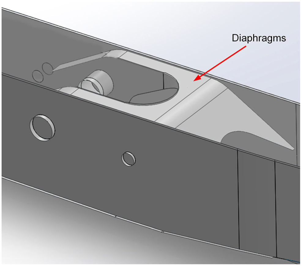
Illustration for the diaphragms of 1# boom.
Footnotes
Acknowledgements
The authors appreciate the engineers Jiantao Li and Qi Zhong at Sany Heavy Industry Co., Ltd for their assistance on the tests and test data analysis.
Handling Editor: Hiroshi Noguchi
Declaration of conflicting interests
The author(s) declared no potential conflicts of interest with respect to the research, authorship, and/or publication of this article.
Funding
The author(s) disclosed receipt of the following financial support for the research, authorship, and/or publication of this article: This work was supported by the National Key Technology Support Program of China (Grant No. 2012BAF02B01).