
Abstract
Taking the hydraulic cylinder for the miter gate in Dateng Gorges Water Conservancy Project as the object, a large slenderness ratio test hydraulic cylinder was designed based on the similarity theory. The buckling analysis of the test hydraulic cylinder was carried out by the finite element method, considering the friction at the supports, the misalignments between piston rod and cylinder tube, and gravity. The results indicate that the stability safety factor is 10.55. A buckling experimental system was established, and the buckling stability of the test hydraulic cylinder was tested for the sliding bearing support and the rolling bearing support at the piston-rod end, respectively. The stability safety factor is over 9.01 and 6.82 relevantly. The similarities and differences among the results of the finite element method, experimental method, NB/T 35020-2013, and two-sections pressure bar method were analyzed. Experimental and analytical results clearly show that the friction at the supports is a key factor in determining the magnitude of the stability safety for large slenderness ratio horizontal hydraulic hoist and utilizing the sliding bearing can effectively improve the stability safety factor.
Keywords
Introduction
Hoist hydraulic cylinder is the core mechanism of the gate hydraulic hoist. The reliability and stability of the hoist hydraulic cylinder are directly related to the safety of the hoist structure. The working stroke of the hydraulic cylinder for the miter gate in Dateng Gorges Water Conservancy Project is 7500 mm, and the total length is 10900 mm when the gate is fully open. The outer diameter of the cylinder is 770 mm and the diameter of the piston rod is 380 mm. The slenderness ratio is 111.24, so this cylinder belongs to large slenderness ratio horizontal hydraulic cylinder. This kind of horizontal hydraulic cylinder has an initial deflection and its buckling mode is the ultimate load coefficient problem (extreme point buckling instability).
Based on the similarity theory, a physical experiment scale model has been built. Using the “Design Specifications for Hydraulic Hoist in Hydropower and Water Resources Projects,” 1 two-sections pressure bar method (TSPBM) 2 , and the finite element method (FEM), the critical buckling load of hydraulic cylinder has been calculated and the test of stability has been conducted. In this paper, these four methods have been compared and analyzed.
Several methods for calculating the critical buckling load of hydraulic cylinder
There are several influencing factors in the calculation of critical buckling load of large slenderness ratio horizontal hydraulic cylinder: one is the friction at supports, the other is the deflection caused by the clearance between the piston and the inner wall of the cylinder and the clearance between the piston rod and the guide sleeve. In general conditions, these factors are ignored in the calculation.
PJ Gamez-Montero et al.3,4 and S Baragetti and A Terranova 5 defined the numerical model that considers self-weight, misalignment, and friction of the hydraulic cylinder. The critical buckling load of the cylinder was calculated and tested. L-H Liu et al. 6 assumed the hinge joints at both ends to be ideal and calculated the horizontal hydraulic cylinder. He held that it was the press bend combination problem (the ultimate load coefficient problem). Tomski and Uzny 7 defined a slender system that considered the rigidities in the constructional nods. Theoretical and numerical research into the stability and free vibrations of the system was carried out. E Narvydas 8 and Y-S Tao 9 used the beam element to simulate the hydraulic cylinder and completed the buckling analysis by FEM.
The method for calculation of critical buckling load on hydraulic cylinder in “Design Specifications for Hydraulic Hoist in Hydropower and Water Resources Projects” NB/T 35020-2013 1 was based on Euler equation and empirical formula


where
Ying-long Guo 2 proposed TSPBM to calculate critical buckling load (Figure 1).
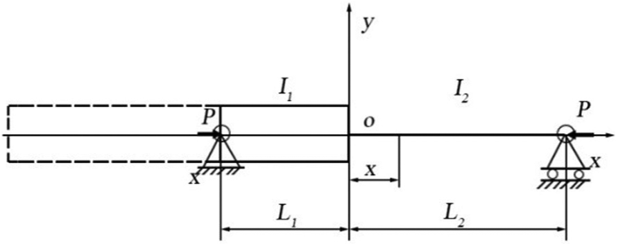
Two-sections pressure bar model of cylinder tube and piston rod.
If the hydraulic cylinder under the axial force P is in a small bending balance, then the pressure P is the critical buckling pressure. A differential equation can be established as

Boundary conditions

Coefficient equations for general solution of equation (3)

Critical buckling load can be determined when the coefficients determinant value of equation (4) is zero. The critical buckling load is obtained by solving the transcendental equation.
TSPBM ignores the initial defect caused by gravity and misalignment, friction at supports, and overhanging section of hydraulic cylinder.
Hydraulic cylinder structure and main parameters
Based on similarity theory, a test hydraulic cylinder has been designed, taking the hydraulic cylinder for the miter gate in Dateng Gorge Water Conservancy Project as prototype. Basic scales have been determined as
Scales of the main parameters.

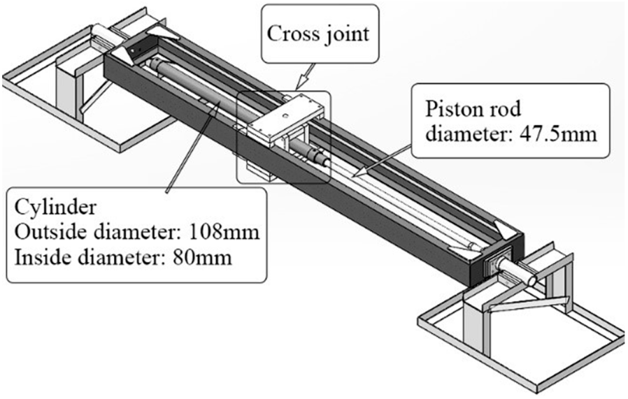
The scheme of structure of test hydraulic cylinder is shown in Figure 2. Full extension of the test hydraulic cylinder (

Structure of test hydraulic cylinder.
Finite element analysis
Eigenvalue buckling analysis of FEM was used in this research using ANSYS. The SOLID185 element is used to simulate the hydraulic cylinder. The material of test hydraulic cylinder is 45 steel so that the elastic modulus is

Finite element model and contact pairs.
Two types of the friction condition are considered: one is ignoring the friction at the joints and the other is considering the joints as rolling friction (
The calculation results indicate that the safety factor considering the friction at joints is 48% larger than ignoring the friction. The frictional condition at both joints is an important factor that affects the buckling safety factor of the hydraulic cylinder.
Experimental work
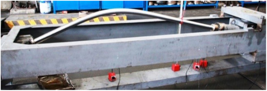
A test bench for critical buckling load has been designed (Figure 4), and the test bench consists of hydraulic cylinder, cross joint, rectangular channel steel frame, and pedestal. In the test, the digital dial indicators are used to monitor the additional deflection caused by the axial load. Six measuring points are arranged (Figure 5). When there is no axial load, the 1# point is the maximum deflection point of the hydraulic cylinder and 5# point is the maximum deflection point of the piston rod. Figure 6 shows the test site.
Test bench.
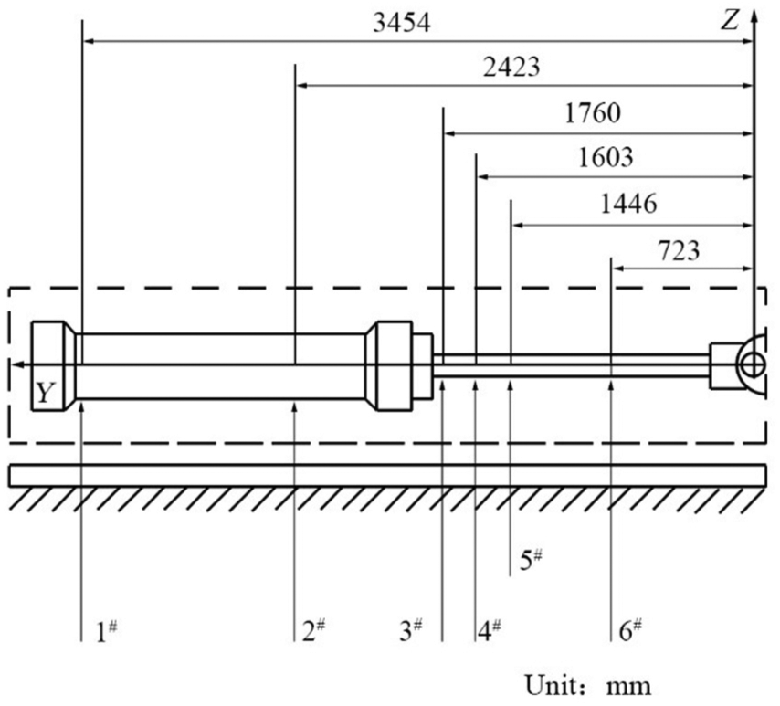
Measuring points arrangement.

Test site.
In the test, the pressure increment is set to 1.0 MPa between 0 and 16.0 MPa. After reaching 16.0 MPa, the pressure increment is set to 0.5 MPa and the pressure is raised until the buckling occurs, then the pressure is determined as the critical buckling load.
In order to analyze the influence of the friction at joint in the piston rod, two types of bearings were used in the piston rod end: sliding bearing (GE50ES) and rolling bearing (21310 cc), and the details are shown in Table 2.
Bearings parameters.

1. Sliding bearing (GE50ES)
When using sliding bearing, the test results show that the critical buckling load is greater than 35.0 MPa and the safety factor is over 9.01.
The pressure–deflection curve of 5# point (Figure 7) shows that in the range of 0 ∼ 35.0 MPa, with rising of pressure, the deflection is close to linear growth and when the axial load reaches 35.0 MPa, the piston rod still does not appear to be unstable.
2. Rolling bearing (21310 cc)
When using rolling bearing, the test results show that the critical buckling load is 26.5 MPa and the safety factor is over 6.28.
The pressure–deflection curve of 1# and 5# point (Figure 8) clearly shows that before 26.5 MPa, with pressure rising, the deflection increases slowly and almost linearly; after 26.5 MPa, the piston rod appears with large deformation, and cannot be restored after unloading. The buckling shape of the piston rod is shown in Figure 9.

The pressure–deflection curve of 5# point using sliding bearing.

The pressure–deflection curve of 1# and 5# points using rolling bearing.
Final instability buckling shape of the piston rod.
Comparison of theoretical calculation and test results
Stability safety factors of the test hydraulic cylinder obtained by four methods are presented in Table 3. NB/T 35020-2013 and TSPBM are based on Euler’s method accounting joints as ideal and ignoring friction, self-weight, and overhanging section of hydraulic cylinder.
Safety factor of four methods.

TSPBM: two-sections pressure bar method; FEM: finite element method.
The results obtained from the FEM without considering friction are close to TSPBM. In finite element calculation, the safety factor considering friction at joints is 48% larger than ignoring friction.
The buckling test indicates that utilizing sliding bearing in the piston-rod end, the critical buckling load is greater than 35.0 MPa and the safety factor is over 9.01; while utilizing rolling bearing, the critical buckling load is 26.5 MPa and the safety factor is 6.28. Finite element analysis and buckling test all suggest that friction in the piston-rod end has a great influence on the critical buckling load and should not be neglected.
The result of finite element analysis considering friction is larger than buckling test. The buckling mode of horizontal hydraulic cylinder is the ultimate load coefficient problem because of the initial deflection. The load–deflection curve (P–y curve) shows that the pressure is reaching critical buckling load

P–y curve of the ultimate load coefficient problem.
Conclusion
By comparison analysis of four methods: NB/T 35020-2013, TSPBM, FEM, and experimental research, the following conclusions are elicited:
NB/T 35020-2013 and TSPBM are conservative and can be used to do a preliminary calculation. Then use the finite element and experimental method to check the results.
The friction in the joint at the piston-rod end has great influence on the stability of hydraulic cylinder. The buckling test indicates that using sliding bearing in the piston-rod end, the critical buckling load is greater than 35.0 MPa; while using rolling bearing, the critical buckling load is 26.5 MPa. Using the sliding bearing can effectively improve the stability safety factor.
The buckling mode of horizontal hydraulic cylinder is the ultimate load coefficient problem. The calculated result by using FEM (
Footnotes
Handling Editor: Jan Torgersen
Declaration of conflicting interests
The author(s) declared no potential conflicts of interest with respect to the research, authorship, and/or publication of this article.
Funding
The author(s) disclosed receipt of the following financial support for the research, authorship, and/or publication of this article: Foundation item: Project (No.2016YFC0402008) supported by the National Key Research Project of China.