
Abstract
A hierarchical optimization strategy is proposed to optimally design constrained layer damping materials patched on the base plate for minimizing sound radiation power. A sound radiation optimization model is established by taking positions and thicknesses of constrained layer damping materials as design variables, and added mass as constraints. The hierarchical optimization procedure is implemented, in which evolutionary structural optimization method is employed to get optimal position layouts of constrained layer damping materials, and genetic algorithm is used to find optimal thickness configurations of constrained layer damping materials by taking the plate with optimal position layouts of constrained layer damping materials as initial structure. Two sound power sensitivities are formulated and compared for position optimization. Numerical examples in which unweighted/weighted objective functions are considered are presented, optimal positions and thickness configurations of constrained layer damping materials patched on the plate are obtained and discussed. The results demonstrate that the proposed strategy is very effective to achieve larger sound power reduction by reconfiguring the thickness of constrained layer damping materials for the results of position optimization.
Keywords
Introduction
Constrained layer damping (CLD) treatments have been widely employed to reduce vibration and sound radiation of flexible structures. The CLD treatments are often attached to the base structure, consisting of a viscoelastic material (VEM) and a constrained layer material (CLM) on top. Thus, while the base structure vibrates, the VEM will subject to a larger deformation, inducing more energy dissipation. The pioneer work in this filed can be traced back to Kerwin 1 who formulated the loss factor of a three-layer flexural beams treated with CLD materials. After that, much work has focused on modeling different CLD structures and predicting their energy dissipation.2,3
Nowadays, considerable research efforts have been devoted to get optimal design of CLD materials on the base structures, as the weight of added CLD materials often has a significant influence on the performance and cost for these structures. Lall et al. 4 carried out an optimum design for a fully CLD covered plate to maximize modal loss factor and minimize displacement response with consideration of VEM parameters, such as densities, thickness, as design variables. Marcelin et al. 5 developed a finite element model for a partially CLD covered beam, and the dimensions and positions of CLD patches were optimized to maximize the damping factor using a non-linear programming method. Zheng and colleagues6,7 determined optimal VEM’s shear modulus and positions/length of CLD patches on a simply supported beam and a cylindrical shell, with objective to minimize vibration energy using a genetic algorithm (GA). Alvelid 8 proposed a shape optimization means for CLD materials to minimize square of normal surface velocity of the base structure, and optimal position layouts of CLD patches were obtained using a piece-by-piece manner. Araújo et al. 9 employed a GA to maximize modal loss factors for hybrid active–passive sandwich composite structures, using thicknesses of the viscoelastic core thickness, the constrained layers ply thickness, and orientation angles as design variables. Sasikumar et al. 10 used Taguchi method to optimize CLD parameters, such as thickness of VEM, CLM, and coverage of the CLD treatments, to maximize modal loss factor for a CLD-treated beam type structure. Maderia et al.11,12 proposed a multi-objective optimization approach based on Direct MultiSearch (DMS) to minimize weight and maximize modal loss factor for a CLD-treated beams/plates.
As mentioned above, the materials parameters of CLD patches were usually selected as design variables. While materials and dimensions along thickness are specified for CLD treatments, it is very natural to formulate the optimization problem as a topological design optimization to determine its shape and positions. El-Sabbagh and Baz 13 carried out a topology optimization procedure with the method moving asymptotes (MMA) to maximize modal damping ratio (MDR) for unconstrained damping plates under a certain volume constraint. Alfouneh and Tong 14 extended a moving iso-surface threshold topology (MIST) optimization method to search optimal layouts of damping materials with maximizing single and multiple MDR of plates as objective functions. Zheng et al. 15 conducted a topology optimization with MMA for optimal CLD layouts in plates with the objective functions and design variables as maximizing MDRs and positions of CLD treatments. Fang and Zheng 16 extended the evolutionary structural optimization (ESO) method to search optimal layouts of CLD treatments on plates with the resonant response as objective functions. Kim et al. 17 designed an optimal damping material layout for a shell structure by employing a topology optimization method, with a interpolation scheme of Rational Approximation of Material Properties (RAMP), to maximize the damping effect. It was found that topology optimization provides a higher modal loss factor, compared with that of the mode shape and the strain energy methods.
The above works on optimal design of CLD treatments have mainly focused on vibration suppression. However, the minimum performance index related to structure vibration, such as MDRs, vibration response, cannot warrant a minimum sound radiation power of flexible structure. To the author’s knowledge, studies on structural–acoustic optimization are very few within the field of application of CLD materials. Zheng and Cai 18 studied optimal CLD layouts with the aim to minimize the sound power radiated by a simply supported, baffled beam. While the procedure was just suitable for simple structure expressed by the analytical models. Zheng et al. 19 formulated an acoustical topology optimization problem for CLD-treated thin plate based on finite element model. A simplified sound power was selected as objective function and the Solid Isotropic Material with Penalization (SIMP) model was introduced to decide the state of CLD elements. Numerical and experimental results showed the volume velocity should also be concerned besides the structural damping, for minimizing sound radiation power at low-frequency range. Zheng et al. 20 developed an acoustical numerical model of a closed cavity coupled with a flexible plate treated with CLD materials, and GA was employed to find optimal locations of CLD patches on the plate for suppressing sound radiation power. The procedure will take higher computational efforts with volume fraction of added CLD materials increasing. Zhang and Kang 21 employed a topology optimization method with SIMP model to optimally design damping layers on the vibrating shell structures. In the optimal design problem, the deign objective was to minimize the structural vibration-induced sound pressure at a specified point in the acoustic medium, and an adjoint variable scheme for the design sensitivity analysis of sound pressure was developed. In the above works, the thickness of CLD materials or damping materials are all assumed to be pre-determined and especially, it is difficult to optimally design thickness and positions configuration of CLD materials for a complex structure in a topology optimization problem simultaneously.
In this article, a hierarchical optimization strategy is proposed to search optimal position and thickness of CLD materials for reducing sound power induced by vibrating of thin plate considering the above discussions. The materials of this article are organized as follows. In section “The sound radiation power of CLD/plate,” the sound radiation power of CLD/plate is derived using finite element method (FEM) and boundary element method. In section “Optimization model of sound radiation,” an acoustic optimization model for CLD/plate is developed in which to minimize sound power is taken as objective function, and the positions and thicknesses of CLD materials are selected as design variables subjected to added mass constraints. In section “Optimization strategy and procedure,” the proposed hierarchical optimization strategy is presented in detail. Numerical examples and discussions are demonstrated in section “Numerical example and discussions.” A brief summary is given in section “Conclusion.”
The sound radiation power of CLD/plate
Figure 1 shows sound radiation model of the plate treated with CLD materials. The flat plate is surrounded by an infinite baffled plate. Arbitrary boundary conditions can be applied to the CLD/plate. Harmonic force with a given excitation frequency is applied on the base plate. Sound radiation power induced by the vibrating plate to half-space is considered with the assumption that structural–acoustic coupling effect is neglected. First, normal vibration velocities of CLD/plate are formulated using FEM. Then sound power is derived using boundary element method.

Sound radiation model of CLD treated plate.
Normal vibration velocities of CLD/plate
A rectangular composite element is considered to model CLD/plate, as shown in Figure 2. It is composed of a base layer, a viscoelastic layer, and a constrained layer. Every node has 7 degrees of freedom. According to the interpolation principle, the general displacement vector

where subscripts c and b denote the constrained layer and the base layer, respectively; z represents transverse displacement of the composite element,

The CLD composite element.
According to deformation relationships among the layers of composite element, shape function matrices of the viscoelastic damping layer can be obtained


where
Hence, the element mass matrix and stiffness matrix of each layer can be obtained based on energy method. For base layer and constrained layer, element mass matrix and stiffness matrix are given as follows


As shape functions of viscoelastic damping layer are related to the thicknesses hb, hc, and hv, the thickness parameters are separated from element mass and stiffness matrices in order to search optimal thickness configurations of CLD materials to minimize sound radiation power. Hence, the element mass and stiffness matrices of viscoelastic damping layer are simply expressed as


where
After assembling the element matrices of base layer, constrained layer, and viscoelastic damping layer, dynamic model of CLD/plate is obtained as

Applying a harmonic force,

Therefore, normal velocity vector of CLD/plate can be expressed as

Sound radiation power of CLD/plate
Sound radiation power of the plate can be expressed using surface sound pressure of vibrating structures

where
For a flat plate surrounded by a rigid infinite baffle plate, the relationship between sound pressure

Furthermore, the surface of flat-plate structure is discretized into small boundary elements with equal area

Equation (13) is rewritten as

in which the matrix

where
Optimization model of sound radiation
In this article, an acoustic optimization model is proposed with to minimize sound radiation power as objective function, position and thickness of CLD materials as design variables and added mass as constraints. Mathematically, the optimization problem can be stated as

where
Optimization strategy and procedure
Optimization strategy
For topology optimization problem of CLD structure, positions of CLD elements are usually taken as design variables to achieve maximum vibration or sound reduction. In fact, thickness of CLD materials also has an important influence on the performance of vibration and sound reduction. Usually, optimal configurations of positions and thicknesses for CLD materials cannot be found together using topology optimization methodology.13–16,18–20 Therefore, for sound optimization problem of CLD structure, a hierarchical optimization strategy is proposed. First, a topology optimization algorithm is employed to find optimal positions of CLD treatments on the base plate, subject to added mass constraints; furthermore, the areas on which CLD materials are pasted are divided into several subareas; an evolutionary algorithm can be used to search optimal thicknesses of CLD materials, subject to the same mass constraint. Hence, optimal configurations of CLD structure are obtained.
Position optimization design of CLD materials
In this article, ESO approach is extended to determine the optimum positions of CLD treatments for minimizing sound radiation power induced by the vibration of the base plate. In the optimization procedure, the inefficient CLD elements are gradually deleted according to sound power sensitivity (SPS) with respect to positions of CLD elements. The SPS is derived in the following section.
SPS
According to equation (14), the sensitivity of sound radiation power with respect to design variable

In equation (17), the sensitivity of normal velocity can be expressed from equation (10)
where
The sensitivity of normal displacement in equation (18) can be derived from the following formula

Therefore, the sensitivity of normal velocity with respect to design variables

In equation (20), the derivatives of global mass matrix and global stiffness matrix with respect to design variables can be expressed using a differential form, given as follows


In equation (22), the derivatives of global mass matrix

Therefore, the sensitivity matrix of sound radiation power of the plate structure with respect to design variables can be expressed as

In addition, another formulation of SPS vector

where

and

in which
Positive value of
Improved filter scheme
A mesh-independent filtering technology 23 is used and improved to obtain the weighted average of the sensitivities within the range of a defined filter radius instead of the original sensitivity. The mesh-independent filtering equation is

where

where
Thickness optimization design of CLD materials
Considering CLD/plate with optimum position layouts of CLD materials obtained using ESO as initial structure, the thickness of CLD materials (VEM and CLM) are further optimized with the same added mass constraints. A design variables vector of the thickness is defined for several CLD materials regions which are divided based on the continuity and regularity of optimum positions layouts, shown as

where n denotes the number of CLD materials regions.
A number of optimization algorithms/methods are available to find optimal thickness of CLD materials, and most of these algorithms require derivatives. Hence, the sensitivities of sound power with respect to thickness variables need to be calculated for each CLD materials region, and optimal thickness of CLD materials can be obtained using conventional optimization procedure, such as sequential quadratic programming (SQP) algorithm which has shown to be robust and efficient. However, it is difficult to obtain the global optimal thicknesses due to the coupling among all the sensitivities of defined CLD materials regions, or the coupling among the thickness variables for each CLD materials region. The GA is such a method to search for the approximation of global optimum. The ergodicity of evolution operations makes GA very effective at performing global search, with no consideration of the coupling among design variables. It can avoid the difficulty that the search procedure is trapped at a local optimum in spite of more time-consuming. In this article, a GA in Zheng et al. 20 is applied to search optimum thicknesses of CLD materials, in which a tournament selection operator, a Laplace crossover operator and a mutation operator are employed. A normalized constraint violations value is defined to deal with the mass constraint.
Optimization procedure
According to the idea of optimization strategy in section “Optimization strategy,” ESO is applied to obtain optimum position layouts of CLD materials, and GA is further used to get optimal thicknesses of CLM and VEM under the premise of optimum position layouts of CLD materials. The whole numerical implementation procedure of the proposed hierarchical optimization design for CLD/plate is shown in Figure 3 and some important steps are described as follows:
Construct the initial design model of CLD/plate in which the base plate is fully treated with CLD materials, and calculate normal vibration velocities and sound radiation power under excitation.
Carry out position optimization of CLD materials/elements bonded on base plate using ESO. The key steps are described as follows: Set the additional mass constraint Calculate the SPSs for CLD elements, and sort the sensitivities in descending order while they are updated using the mesh-independent filter technology. Determine and delete DR CLD elements according to descending order of the sensitivities, calculate the actual added mass Update the design model of CLD/plate, and recalculate the sound radiation power and sensitivities. Determine whether the mass constraint is satisfied. If it is not satisfied, go to step 3, otherwise, go to step 6. Output optimum positions layouts of CLD materials.
Keep the mass constraint unchanged, the thickness of CLD materials is optimized using GA. The specific steps are described as follows: Set the parameters of GA, including the number of population N and evolutionary generations G, crossover probability and mutation probability, parameters of crossover operator and mutation operator. Partition the CLD position layouts into several subareas, initialize the thicknesses design vector corresponds to the subareas, and initialize the evolutionary population in which the number of individuals is set to be 2 × N. Sort the individuals in ascending order based on the values of objective function and constraint violation, and the former N individuals are selected to as the evolutionary population. Get the parent individuals by carrying out tournament selection operator, obtain the offspring by implementing the crossover operator or mutation operator and calculating the sound radiation power and constraint violation value. Merge the parent and the offspring, and sort them; the new evolutionary population is obtained by selecting the first N individuals. Determine whether termination condition is satisfied. If it is satisfied, the objective function is convergent, go to step 7; otherwise, go to step 4. Output the final optimization results for CLD/plate. Stop.

The flow chart of proposed hierarchical optimization strategy.
Numerical example and discussions
A rectangle CLD/plate in an infinite baffle plate in which four edges of the base plate are clamped is considered, and as initial design, the plate is fully treated with CLD materials. The proposed hierarchical optimization strategy is employed to search optimal position and thickness configurations of CLD/plate for minimizing the sound radiation power. The dimension of base plate is 400 × 300 × 0.8 mm, and the physical parameters are listed as follows: Young’s modulus is 70 GPa, Poisson’s ratio is 0.3, and density is 2800 kg/m3. The CLD treatment is composed of a 0.1 mm viscoelastic layer and a 0.1 mm aluminum layer (constrained layer) of which the thicknesses of 0.1 mm are defined as the initial value. The viscoelastic layer has the complex shear modulus of 4 × 10⁶(1 + 0.5j) Pa, Poisson ratio’s of 0.5, and density of 1200 kg/m3. The constrained layer has Young’s modulus of 70 GPa, Poisson’s ratio of 0.3, and density of 2700 kg/m3.
The CLD/plate is discretized into 16 × 12 elements, and a unit harmonic force is applied at central point. It is apparent that the sound power is suppressed significantly while the plate is fully treated with CLD materials, as shown in Figure 4, and the resonant frequencies are matched with that of the first and fourth structural modes of the plate, as shown in Figure 5. It is noted that reference sound power, 10−12 W, is used to calculate the sound power level in this article.

Sound radiation power for the base plate and the fully treated CLD/plate.
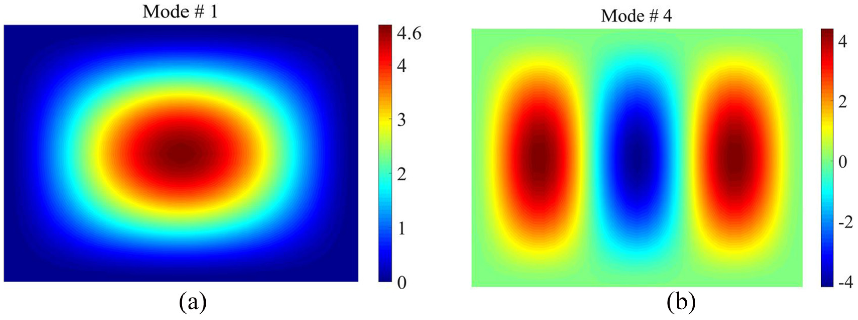
First and fourth structural modes of the CLD/plate: (a) 61.36 Hz and (b) 171.24 Hz.
In the following optimization procedure, the mass fraction of CLD material is limited to 50% of full coverage with initial configurations. The objective function is to minimize the sound power at the two resonant frequencies (corresponding to the two structural modes). The target modal frequencies are updated at each iteration to construct the excitations, and modal assurance criterion (MAC) 24 is introduced to keep the consistency of target modes.
Discussions on SPSs
ESO is employed to search optimal position layouts of CLD materials on the base plate, and the evolutionary direction is decided by sorting SPS. Hence, minimum sound power based on the two SPSs formulations in section “SPS” is compared firstly (method 1—SPS formulated in this article; method 2—SPS formulation in Zhang et al. 22 ). In optimization procedure, DR = 4 elements are deleted at each iteration based on the criterion: if there are positive and negative SPS simultaneously, the elements with largest positive SPS are deleted first, and then the elements with negative SPS are deleted; if the sensitivity is all negative, the elements with smallest absolute value of the sensitivity are gradually deleted.
Figure 6 shows minimum sound power and natural frequencies corresponding to the first and the fourth structural modes with deleting ratios of CLD materials increasing. The difference between minimum sound power obtained by employing the two SPS formulations at the first structural modal frequency is very small, and smaller sound power at the fourth modal frequency can be obtained using method 1, as shown in Figure 6(a). Furthermore, the difference between modal frequencies obtained by the two SPS formulations is very small, as shown in Figure 6(b). However, it will spend much more time to implement the optimization procedure while the method 2 is used, as shown in Table 1. Hence, method 1 is employed in the following optimization procedure.

Optimal results obtained according to the two SPS formulations: (a) sound radiation power and (b) natural frequencies.
Implementation time with different SPS formulations/second.

To minimize sound power at individual resonant frequency
The sound radiation power at first and fourth resonant frequencies is minimized respectively using the proposed hierarchical optimization strategy.
Position optimization of CLD materials
First, optimal positions of CLD patches on base plate are searched using ESO. As the mesh-independent filter radius has important influence on optimal results, minimum sound power and natural frequencies with varied deleting ratios of CLD materials under different filter radii are presented, as shown in Figures 7 and 8. While the mesh-independent filter radius is equal to 1, the minimum sound power is very close to that of without consideration of mesh-independent filtering technology, and the influences on natural frequencies are also small.
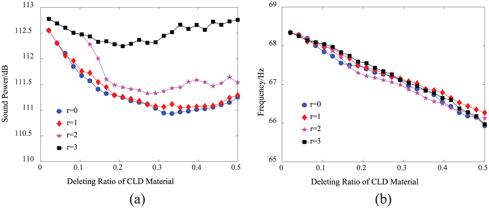
Minimum sound power and natural frequencies corresponding to first mode under different filter radii: (a) minimum sound power and (b) the first modal frequency.
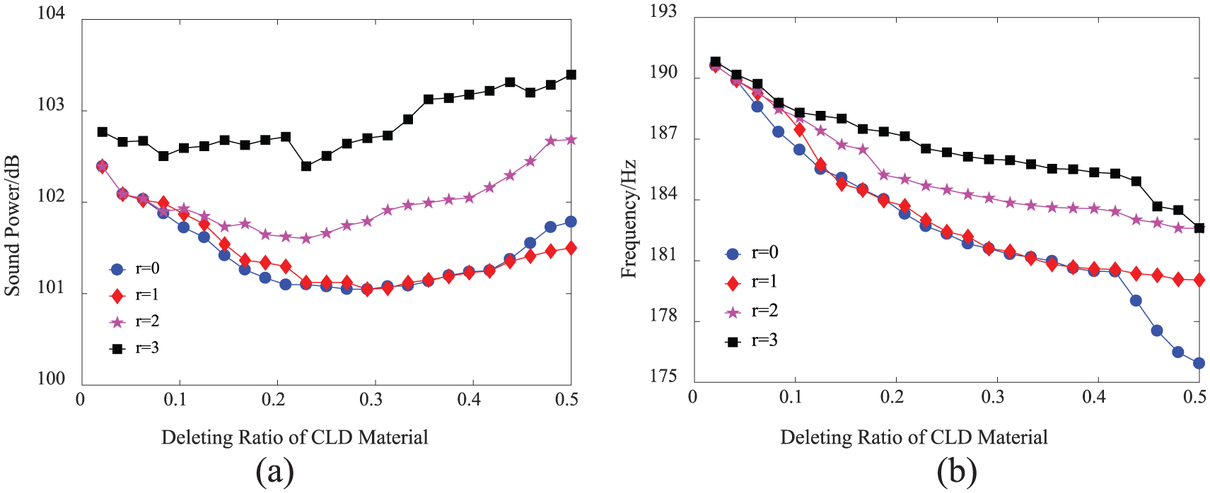
Minimum sound power and natural frequencies corresponding to fourth mode under different filter radii: (a) minimum sound power and (b) the fourth modal frequency.
For minimizing sound power at first modal frequency, optimal position layouts of CLD materials with 50% mass fraction under different filter radii are presented in Figure 9. While the mesh-independent filter radius is equal to 1, optimal layouts of CLD materials are more regular than that of without consideration of mesh-independent filtering technology, as shown in Figure 9(a) and (b). While the filter radius is equal to 1 and 2, optimal position layouts of CLD materials shown in Figure 9(b) and (c) are very close, but sound power corresponding to the former is smaller. Hence, optimal position layouts of CLD materials while the filter radius is equal to 1 are selected as the initial structure for thickness optimization of CLD materials to further minimize sound power at first modal frequency.

Optimal positions of CLD materials with 50% mass fraction for minimizing sound power at first modal frequency: (a) r = 0, (b) r = 1, (c) r = 2, and (d) r = 3.
Similarly, optimal position layout of CLD materials shown in Figure 10(b) is also selected as initial structure for thickness optimization of CLD materials to further minimize sound power at fourth modal frequency.
Optimal positions of CLD materials with 50% mass fraction for minimizing sound power at fourth modal frequency: (a) r =0, (b) r = 1, (c) r = 2, and (d) r = 3.
Besides, MACs for the first and fourth modes in optimization procedure are also monitored. For simplicity, only the MACs for first and fourth structural modes while filter radius equal to 1 are illustrated, as shown in Figure 11. It can be concluded that the structural mode shapes are almost unchanged in the optimization procedure.

MACs for first and fourth structural modes in optimization procedure (r = 1): (a) MAC for first mode and (b) MAC for fourth mode.
Thickness optimization of CLD materials
Second, the GA is used to optimize the thickness of CLD materials. The position layouts of CLD materials in Figures 9(b) and 10(b) are selected as initial structures in this stage and divided into five areas and nine areas shown in Figure 12. Considering the symmetry, for position layouts of CLD materials in Figure 9(b), three subareas are defined, S1 = A2, S2 = A1 + A4 and S3 = A3 + A5, respectively (shown in Figure 12(a)), and then the design variable vector for thicknesses {h1c, h1v, h2c, h2v, h3c, h3v} of CLD materials in S1, S2, and S3 is defined. Similarly, for position layouts of CLD materials in Figure 10(b), S1 = A2 + A6, S2 = A4, S3 = A1 + A7, and S4 = A3 + A5 + A8 + A9 are defined (shown in Figure 12(b)), and the corresponding design variable vector for thicknesses {h1c, h1v, h2c, h2v, h3c, h3v, h4c, h4v} is also defined.

Partitions for position layouts of CLD materials: (a) Initial structure for thickness optimization at first modal frequency; and (b) Initial structure for thickness optimization at fourth modal frequency.
The mass fraction of CLD material is still limited to 50%, and the thickness range of CLMs and VEMs are set from 0.01 to 0.2 mm. Then the GA is implemented and algorithm parameters are as follows: population number is 50, evolutionary generation is 50, crossover probability is 0.9, and mutation probability is 0.1.
Optimal thickness of CLD materials at each area are obtained for minimizing sound power at first and fourth modal frequencies, listed in Table 2. The results suggest more CLD materials should be pasted on the areas with larger deformations by analyzing Table 2 and Figure 5. The thickness ratios of CLM and VEM are close to one at all the areas (bold values of hc and hv in table 2).
Optimal thickness of each region to minimize sound power at first and fourth modal frequencies.

Note: The bold values means more CLD materials should be pasted on the areas with larger deformations of the base plate.
Minimum sound power obtained by implementing the hierarchical optimization is presented in Figure 13. Compared to the sound power of full CLD coverage at first modal frequency, 1.52 dB of the sound power reduction can be achieved while position optimization is implemented, and 4.55 dB of the sound power reduction can be obtained while thickness optimization of CLD materials is carried out by considering optimal position layouts as initial design. However, sound power at the fourth modal frequency increases when position and thickness of CLD materials are optimized for minimizing sound power at first modal frequency. The similar results can be obtained while minimizing sound power at the fourth modal frequency; 1.28 and 4.62 dB of sound power reduction at the fourth modal frequency can be obtained for position optimization and further thickness optimization, respectively; however, sound power at the first modal frequency increases.

Minimum sound power obtained using the proposed strategy: (a) sound power at first resonant frequency and (b) sound power at fourth resonant frequency.
To minimize weighted sound power at resonant frequencies
Results and discussions
Minimizing sound power at first and fourth modal frequencies simultaneously that can be viewed as a multi-objective optimization problem. In practice, a weighted sum of objective functions is generally employed, and the effective feasible results can be obtained, although they may not locate all the Pareto solutions. Here, a weighted objective function is expressed by

where W1 and W4 are sound power at first and fourth modal frequencies;

Two cases are considered. For case 1, the thickness range of CLM and VEM is the same as that in section “Thickness optimization of CLD materials.” As a comparative example, for case 2, the thickness range is changed, varying from 0.01 to 0.3 mm. For the two cases, 50% mass fraction of CLD material is still considered as constraints and the hierarchical optimization procedure is implemented. Optimized position layout of CLD materials is obtained using ESO, and partition into four subareas, S1 = A3, S2 = A2 + A5, S3 = A4 + A7, and S4 = A1 + A6, as shown in Figure 14. Then corresponding thicknesses variables, {h1c, h1v, h2c, h2v, h3c, h3v, h4c, h4v}, is defined, and optimal thickness configurations obtained using GA for the four subareas are listed in Table 3 for the two cases. Analyzing Figure 5 and Table 3, it can be inferred that more CLD materials should be arranged at the area, S1, with larger deformations of first mode due to higher sound power contribution of first structural mode; less CLD materials should be pasted at the area S2 as smaller sound power contribution of fourth structural mode. Furthermore, the thickness ratios of CLM and VEM should be close to one at both the areas (bold values of hc and hv in table 3).

Optimal position layout of CLD materials with weighted sound power.
Optimal thickness of each subarea with weighted sound power (Case 1 and Case 2).

Table 4 gives sound power obtained by implementing the hierarchical optimization with weighted objective function for the two cases. As a comparison, unweighted sound power in section “To minimize sound power at individual resonant frequency” is also listed in Table 4. As seen from Table 4, it is apparent larger sound power reduction at the two resonant frequencies can be obtained simultaneously as weighted objective function is employed. While the thickness range of CLD materials is expanded, larger sound power reduction can be further achieved.
A comparison of sound power with different objective functions.

The influences of weight coefficients
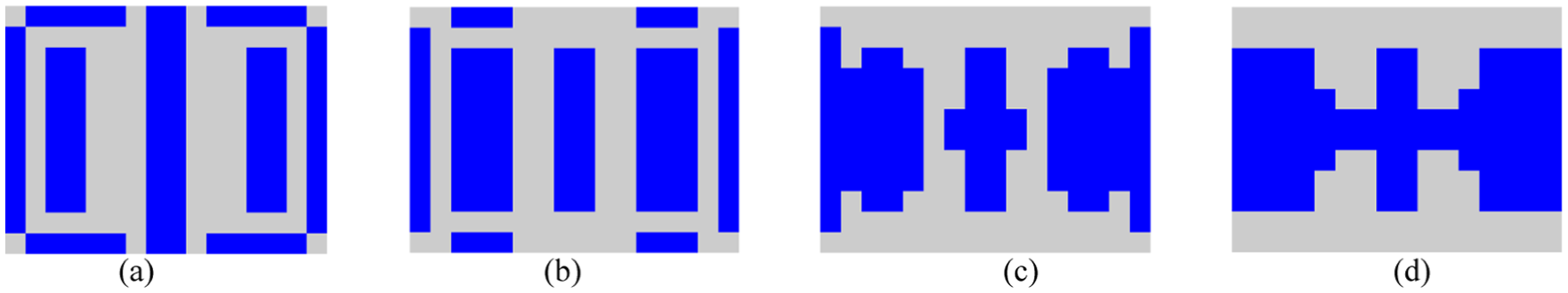
The weight coefficients in above section are decided according to the discussions in this section. Figure 15 gives the optimal results with varied weight coefficients while position optimization design is carried out. As can be seen from Figure 15, with weight coefficient
Sound power with different weight coefficients (
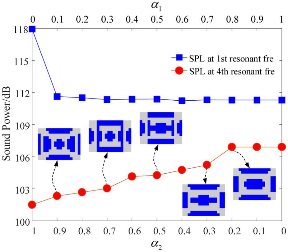
Taking the above case 2 as an example, the influences on optimal results induced by varying weight coefficients are also discussed for thickness optimization of CLD materials. The sound power at first and fourth modal frequencies is obtained under varying weight coefficients
Sound power with different weighted objective functions.

Optimal thickness of each subarea with different weighted objective functions.

Conclusion
In this article, a proposed hierarchical optimization strategy is investigated to optimally design positions and thicknesses of CLD materials for minimizing sound radiation power of a vibrating plate. With a given mass fraction, ESO method is employed to obtain optimal position layouts of CLD materials and GA is used to search optimal thicknesses CLD materials for each subarea which are obtained by the partition of optimal position layouts. For position optimization, an effective SPSs formulation with less computational time is derived and an improved filter scheme is also defined for determining filter radius easily. The proposed strategy can also be implemented by combination of other topologies optimization method and other intelligent optimization algorithms.
Numerical examples demonstrate the proposed hierarchical optimization strategy can enhance the reduction of sound power by reconfiguring thickness of CLD materials with a given mass fraction based on the optimal results of topology design. To minimize sound power at individual resonant frequency, the results show larger sound power reduction can be achieved by reconfiguring thickness of CLD materials with a given mass fraction. More CLD materials should be pasted on the areas with larger deformations. For a weighted objective function, more CLD materials should be pasted on the areas with larger deformations which correspond to the structural mode with higher sound power contribution. The optimal weight coefficients are suggested using the ratios of sound power at resonant frequencies obtained from the initial fully treated CLD/plate.
Footnotes
Handling Editor: Ali Kazemy
Declaration of conflicting interests
The author(s) declared no potential conflicts of interest with respect to the research, authorship, and/or publication of this article.
Funding
The author(s) disclosed receipt of the following financial support for the research, authorship, and/or publication of this article: This research is supported by Shanghai Automotive Industry Science and Technology Development Foundation of China (grant no. 1744) and Shanghai Sailing Program (grant no. 18YF1418500).