
Abstract
The wireless power transfer shows great potential in the future for its safety and convenience. Autonomous underwater vehicle is one of the important tools to explore and develop oceans. In this study, we develop and analyze a wireless power transfer system based on magnetic resonance coupling to charge the autonomous underwater vehicle underwater. We have adopted a way that energy transmission underneath the vehicle and the coils in the wireless power transfer system were proposed to obtain a higher mutual inductance based on the shape of the vehicle in this study. In addition, we analyze the equivalent circuit model and propose a kind of impedance matching network to maintain system security. The coils we used in the proposed system are 20 turns and their radii are 70 mm. The system works well with 100 W output and 72% efficiency.
Keywords
Introduction
Since Tesla coils were invented by Nikola Tesla in 1889, 1 the wireless power transfer (WPT) has been developing and it enters into a new development period since researchers at MIT proposed strongly coupled magnetic resonance. 2 For the advantage of being safe and convenient, the WPT attracts much attention and shows great potential in the future and it has been widely researched in the field of electric vehicles (EVs),3,4 electronics, 5 implantable devices,6,7 and special applications. 8 Due to the relatively wide transmission distance and high efficiency, magnetic resonant coupling wireless power transfer (MRWPT) is one of the appealing WPT approaches (Figure 1).

The example of the WPT system for AUV.
Underwater vehicles play an irreplaceable role in resource exploration and marine landform observation. Autonomous underwater vehicle (AUV) is a new generation of underwater vehicle which owns complex intelligent control systems as robotic aircrafts.9,10 It has the advantages of superior mobility, safety, and intelligence and has become an important tool for various underwater tasks. For reasons that the Torpedo AUV can provide much room and has less liquid resistance, it becomes one of the main AUVs. However, the endurance of AUV is limited by battery capacity. To enhance their cruising ability, it is advisable to build an underwater docking station which guides AUV into dock.11–13 The ducking station collects and stores energy from wave and tide. 14 When the energy that AUV carries down to a certain level, it goes to the nearest underwater docking station to get energy supplies. Although it is hard to transfer energy to AUV through the traditional cable method in underwater environment, the WPT is the best choice.
In the last decade, researchers have done a lot of work in optimization design, model analysis, and impedance matching. Tsai et al. 15 proposed a kind of directional antenna which can produce a higher flux density to the receiver. Researchers demonstrated a wearable WPT system using conductive thread coils for wearable device applications working at 6.78 MHz. 16 The study by Zhang et al. 17 compared WPT systems with different structures and obtained the conclusion that the WPT system with higher energy efficiency within a wider range of loads can be obtained by properly designed three-coil systems. Most of the research on the WPT system is being carried out in air medium, but there are some differences between underwater condition and air medium, such as high pressure and eddy current loss (ECL) in seawater and under closed condition. The studies by Kojiya et al. 18 and Zhou et al. 19 provide some applications of the WPT system underwater, but their studies on inductive contactless power transfer (ICPT) were easily affected by transfer distance or misalignment. Although Lin et al. 20 introduced their work about underwater docking systems and achieved success, the coils they used are slightly heavier and influence the fluid performance of AUV.
For the reason that most of the WPT systems undersea are based on ICPT which require a high coupling coefficient, we try to apply MRWPT for AUV charging underwater. In this article, we analyze the condition that Torpedo AUV is charged in an underwater docking system. For the reason that a two-coil WPT system is widely used and multi-coil structure systems can be transformed into its style, we choose it for the study. In section “Coils,” we proposed an optimized coil according to the shape of AUV and compared it with the traditional coil based on the finite element calculation. The contrasting results show that the mutual inductance of recommended coils is better than that of the traditional coils. In section “Circuit model,” we analyzed the circuit model and obtained the expressions of efficiency. The power transmission efficiency varies with the transmission distance when the resonant frequency of the system and load are certain. In section “Experiment and results,” the experiments performed in air and underwater are presented. We find that radial-eccentric distance is more influential than axi-eccentric distance and angle-eccentric distance. The total system can work well underwater with the transmission power of 100 W and efficiency of 72%. Finally, some concluding remarks were provided in the section “Conclusion.”
Coils
Normally, the detection equipment is installed in the head and the main thruster is installed at the tail, so we can only install coils in the middle part. And the transmission distance is relatively long, the magnetic core cannot improve coupling coefficient effectively. Besides, the magnetic core brings the difficulties such as ECL in the core and complex structure of the coil. Therefore, we use coils without cores in the underwater MRWPT system. Since AUV works for a long time in the high-pressure condition, it is crucial to ensure the stability of the vehicle structure and make full use of its internal space. The diameter of the target AUV is 324 mm. Based on the above considerations, the space that is used to install the secondary coil is limited to 200 mm diameter and 100 mm height. In order not to influence the shape of the vehicle, we make the encloser for coils using Nylon 6. The coil is wound on the nylon column and is installed into the encloser. The encloser is fixed on AUV and the energy supply module. Generally speaking, the entire WPT system consists of an inverter, a primary network, a secondary network, and an AC–DC boost module. For the reason that the loss in inverter and rectifier increases rapidly as the work frequency increases, the resonant frequency cannot be very high. So the resonant frequency we choose is about 200 kHz. Compared with the primary coil, the secondary coil works in a more complex environment, so we choose it as the research object. Once the secondary coil is certain, the primary coil is chosen as the corresponding type. There are two basic types of coils: disk or cylindrical coils. The quality factor Q is a key parameter which stands for the ratio of stored energy and dissipated energy of an inductor. Mutual inductance is one of the key parameters in the flow analysis. In this part, we choose one better coil type by comparing the Q values, and then optimize it to suit the AUV shape. In order to facilitate the comparison, we treat them as a cylindrical symmetry model. It is mentioned that the radius of a disk coil means the radius of the outmost turn coil.
First, we obtain the resistance and inductance of coils through simulation calculation in the software COMSOL 5.2a. Then we can obtain their quality factors. For a series resonant system, the expression of the quality factor is as follows

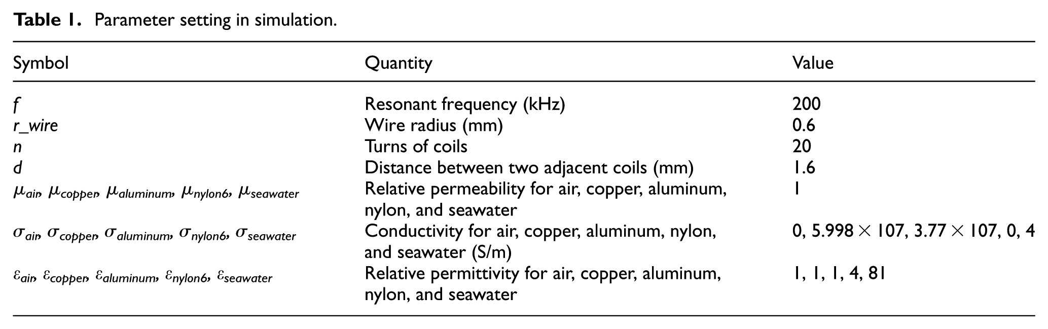
where ω, Lcoil, and Rcoil are the resonant frequency, inductance, and resistance, respectively. The simulation is set as shown in Figure 2 and the parameters are shown in Table 1.

Simulation geometry and result diagram: (a) geometry of cylindrical coil in simulation, (b) geometry of disk coil in simulation, (c) simulation result of cylindrical coil, and (d) simulation result of disk coil.
Parameter setting in simulation.
From Figure 3(a), the resistance increases approximately linearly as the radius increases when the radius is between 55 and 80 mm. But the resistance increases faster when r > 80 mm. The reason for this phenomenon is that ECL in the metal shell and seawater increases fast when the coils are close to the metal shell and it is transformed into coil resistance. From Figure 3(b), we can see that the inductance of the cylindrical coil increases first and then decreases with the increase in radius. The inductance of the disk coil increases with radius, but the increasing tendency is more and more slow. This is because the eddy current generates reverse flux linkage, which leads to inductance reduction. From Figure 3(c), it is obvious that Q of the cylindrical coil is larger than that of the disk coil when r < 80 mm and decreases rapidly with the increasing radius when r > 70 mm. Q of the disk coil increases first and then decreases. When the coils are close to the metal shell, their Q values decrease fast. Higher Q means less power loss in coils and large coils bring high mutual inductance, so we choose the cylindrical coils and their radius is 70 mm. But there is a question that the surface of AUV is cylindrical. It means that the transmission distance will become larger if we use traditional coils. In consideration of the fact that the diameter of AUV is 324 mm, we make the upper surface of enclosers cylindrical with the diameter of 324 mm. In order to decrease the transmission distance, we change the shape of the coils slightly and find that the transmission distance is minimum when the shape of the coils is the same with the enclosers’ upper surface. Since the deformed structure and the traditional coil are similar, we do not compare their Q values. So we proposed the deformed coils shown in Figure 4 and compared their mutual inductance values with those of the basic cylindrical coils.
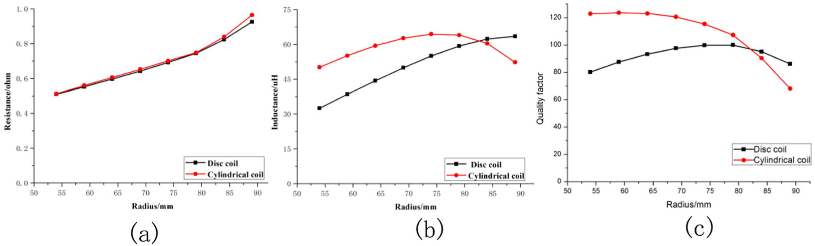
(a) Curves of coils’ resistance with radius, (b) curves of coils’ inductance with radius, and (c) curves of coils’ quality factor with radius.

The deformed cylindrical coils.
From Figure 5, we can learn that the mutual inductance of the deformed cylindrical coils is much higher than that of their basic form, so we choose them in the underwater MRWPT system and the values are n = 20 and r = 70 mm.

The mutual inductance between the primary and secondary coils.
Circuit model
The circuit model of the WPT system is illustrated in Figure 6. The DC source supplies power to the inverter and then generates a high-frequency AC. Through the magnetic coupling between the primary and secondary coils, energy was transferred to the secondary side and then power is supplied to load after rectification. Comparing with microwave, the resonant frequency is very low, so we do not take the capacitive and radiative effects into consideration. The power loss in the total system includes power loss in the inverter, boost circuit, connecting lines, and coils and ECL in seawater and the metal shell. As for the ECL in seawater and the metal shell, it is hard to obtain its numerical value because the boundary is complex and irregular. But we can obtain their simulation values and convert it into equivalent resistance or measure its value under working condition.

The circuit model of the WPT system.
In the circuit model, the subscripts p and s denote the primary and secondary coils, respectively. I is the effective current value in the coil; L is the inductance of the coil; C is the compensation capacitor; M is the mutual inductance; RL0 is the load; Rp and Rs are the sum of the connecting line resistance, wire resistance of the coils, ECL equivalent resistance from the primary and secondary coils, respectively.
As for the power loss in the inverter and boost circuit, we can obtain PLinv and PLboost from Lin et al. 20


where Ig is the drain current just before the switching transient; Vg is the input voltage of the inverter; TS is the time of the current rising, current falling, voltage raising, and voltage falling; and RDS_on is the conduction resistance of the power components. Its voltage drop is Vdrop.
As for the WPT system, we analyze it in the simplified circuit (Figure 7). According to Kirchhoff’s law, we can obtain


The simplified circuit model of the WPT system.
When the system is in a resonant state, there is

From equations (4) and (5), we can obtain the reflection impedance Rref

During the charging process, M will change because ocean current influences the degree of misalignment. Rref will decrease rapidly when the M value decreases and the input current will become too high to destroy the inverter for a simple series resonant WPT system. So it is very important to keep the equivalent primary resistance constant. In this article, we use the primary impedance matching network to avoid the equivalent primary resistance becoming very little and control the input power.
From the primary circuit, we can learn that

Changing the values of CP1 and CP3, we can obtain
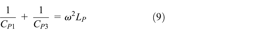
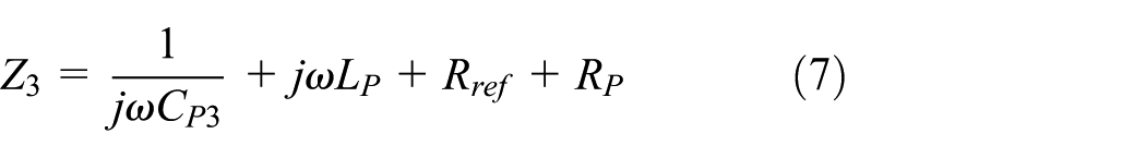
Substituting equation (9) into equation (8), we can obtain

So it is easy to obtain the expression of Z1

Making CP2 equal to CP3 and L1 equal to LP, we can obtain Z1 easily

From the expression of Z1, we learn that Z1 changes with CP1 and M when ω is constant. So it is possible to make Z1 constant by adjusting CP1 when M changes. For the simplified circuit model, the power is consumed on RP, RS, and RL, so we can obtain the transfer efficiency of the simplified circuit

Once the efficiency of the inverter and boost circuit is certain, ηsim is critical for the efficiency of the MRWPT system. From equation (13), we can learn that ηsim increases with the increase of Rref and decreases with the increase of RP or RS. For the reason that RL cannot change artificially and the frequency will influence PLinv, the ways to increase Rref are improving mutual inductance and reducing RS. The main part of RP and RS is ECL equivalent resistance, so we cannot reduce them sharply. The suitable means to improve efficiency is to the keep mutual inductance large enough.
Experiment and results
In this article, we aimed to design an MRWPT system for Torpedo AUV, the diameter of which is 324 mm, so a prototype is made to test the MRWPT system. The experimental setup is shown in Figure 8. The inverter and a primary impedance matching network are set in a metal box and the primary coil is fixed on it. The secondary coil is fixed on a section of the vehicle and the AC–DC boost circuit, secondary network, and load are set in the same section. When the vehicle is in the suitable position, DC power is supplied to the inverter and energy transfer to the vehicle is started.
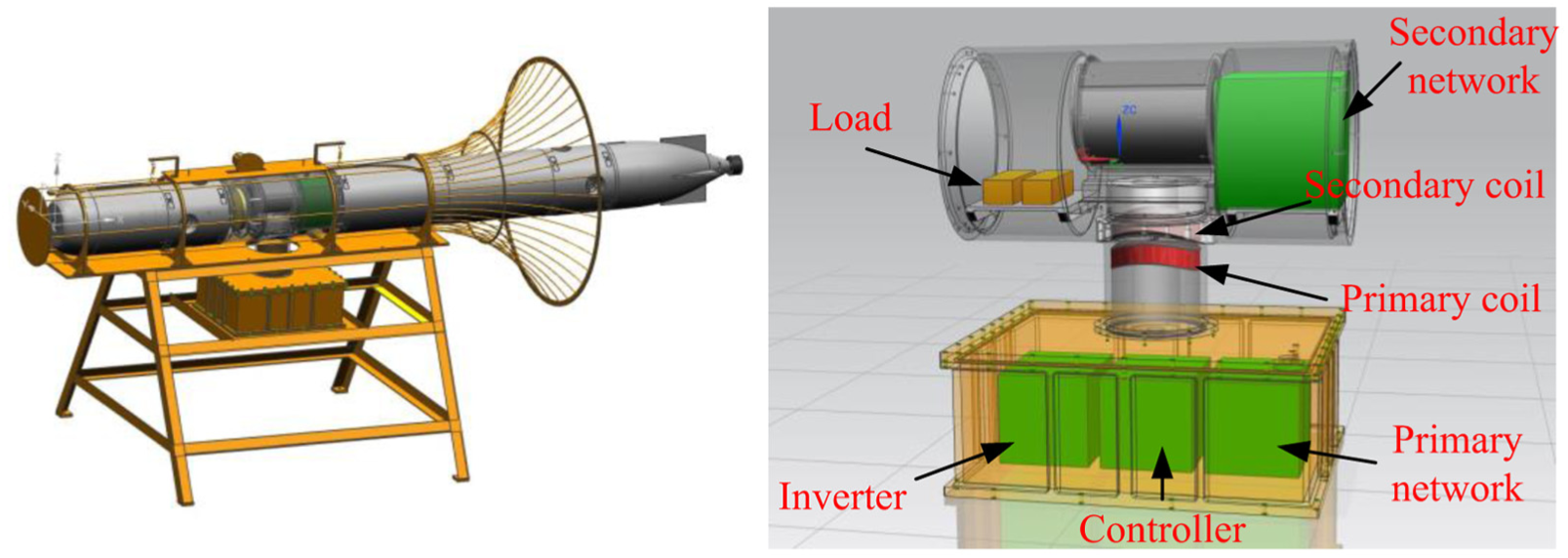
Prototype model.
For the reason that it is hard to know the misalignment condition underwater, we perform a series test in the air condition and obtain the relationship between misalignment and transmission efficiency. In this experiment, we can obtain the voltage (Uin) and current (Iin) of the DC power and the voltage (Uout) and current (Iout) of the load by the controller chip. So it is easy to calculate the efficiency of the entire system
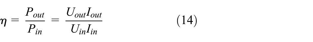
Since the eddy current will influence the inductance of the coils, we can observe LP > LS. In order to make the two coils resonant at the same frequency, we make the secondary coil resonant and treat the frequency as the work frequency. Then we make the primary coil resonant at work frequency by controlling the compensation capacitances. We use two series resistors as the load and make use of the RCL analyzer to obtain the values of LP, LS, RLL0, RP, and RS. The resistance is measured at the resonant frequency. In experiments, we change the input power by controlling the DC source and calculate the efficiency when Pout > 100 W (Figure 9). The experimental parameters are shown in Table 2.

Experimental setup.
Parameters in experiment.

From Figure 10, it is obvious that misalignment will reduce the power transmission efficiency. The axi-eccentric distance and angle-eccentric distance almost have the same influence on efficiency and the system efficiency is more than 70% when the eccentricity distance is below 16 mm. But the radial-eccentric distance are more influential than axi-eccentric distance and angle-eccentric distance. So it is crucial to reduce the eccentricity distance, especially the radial-eccentric distance when we perform the experiment underwater (Figure 11). Because it is difficult to figure out the docking status between the AUV and base station underwater, we test the system again and again. The experimental results are shown in Table 3.

Curve of transmission with eccentric distance.

The image of experiment of the prototype.
The experimental results underwater.
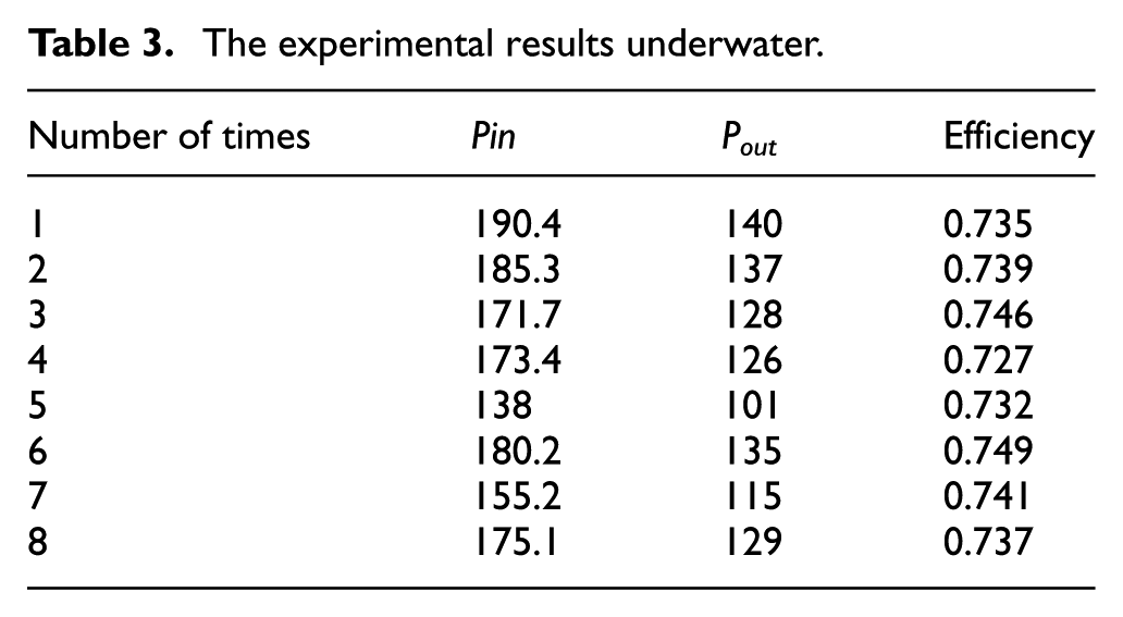
The result of the experiment shows that the total system can work well underwater with the transmission power of 100 W and efficiency of 72%. In total, the transmission efficiency is not very high for the reason that the resistances are large. So we will optimize the structure to reduce ECL in the future.
Conclusion
It is advisable to build an underwater docking station and supply energy to AUV through the WPT system. This article is proposed in such a way that energy transmission underneath the vehicle and the coils in the WPT system was deformed to obtain higher mutual inductance based on the shape of the vehicle. Through the study of eccentricity, we find that radial-eccentric distance is more influential than axi-eccentric distance and angle-eccentric distance. The experimental results show that the total system can work well underwater with the transmission power of 100 W and efficiency of 72%. In order to improve the efficiency, we will work to reduce ECL in the future.
Footnotes
Handling Editor: Chenguang Yang
Declaration of conflicting interests
The author(s) declared no potential conflicts of interest with respect to the research, authorship, and/or publication of this article.
Funding
The author(s) disclosed receipt of the following financial support for the research, authorship, and/or publication of this article: This work was supported in part by the Natural Science Basic Research Program of Shaanxi Province under Grant No. 2018JM5033.