
Abstract
Due to the presence of brush and slip ring in the excitation method of electrically excited synchronous motors, this article proposes a new excitation method - non-contact excitation system. This method transfers electrical energy from the stator to the rotor through magnetic coupling, replacing slip ring and brush. However, the magnetic coupling coils at the primary and secondary ends of the system will deviate, which will affect motor operation quality. In order to effectively reduce the changes caused by mutual inductance, this article proposes an improved particle swarm optimization algorithm for mutual inductance identification. This improved algorithm can effectively reduce the shortcomings of low accuracy and easy to fall into local optima in particle swarm optimization. Simulation and experimental results show that the improved particle swarm optimization algorithm can improve search accuracy.
Keywords
Introduction
Electric vehicles include three core components: power battery, motor, and motor drive technology.1–3 Among them, the motor plays a crucial role. Therefore, the research on the high-efficiency motor of the electric vehicle has significant scientific, economical and practical social value.4–7
Permanent magnet synchronous motors (PMSMs) have high costs, and its magnetic field control is difficult during motor operation.8–11 For electrically excited synchronous motors (EESM), the stator and rotor are independently excited, so magnetic field control is relatively simple.5,12,13 However, the excitation method of EESM needs brush and slip ring, which can cause the brushes to wear out the motor during operation. 14 Therefore, there is an urgent need for a new brushless excitation method.
To deal with the problems, this article proposes an innovative excitation method—non-contact excitation system. For this system, the absence of brushes eliminates friction caused by brush contact, creating a safer working environment and extending the service life of EESM. The core component of the system is the magnetic coupling coils on the stator and rotor, which transfer energy through magnetic coupling. 15 The primary coil is fixed on the stator and remains stationary, while the secondary coil is installed coaxially with the rotor and rotates accordingly. By setting parameters, the primary and secondary of the system resonate simultaneously, and AC voltage is transmitted from the stator coil to the rotor coil through magnetic coupling. 16 Afterwards, the AC voltage is rectified and transmitted to the rotor to complete the excitation process. The excitation process needs no brush and slip ring, making it a safe brushless excitation method. 17
Due to the physical isolation between the coupling coils, leakage inductance is inevitable during energy transmission. Capacitance compensation can avoid this disadvantage.18–20 LCC-S topology has become a research hotspot recently, and the output voltage of the topology is less affected by component parameters, which is beneficial for constant voltage charging,21,22 therefore, this article chooses LCC-S topology as compensation topology.
Non-contact excitation motors are installed on electric vehicles, and the operating conditions of electric vehicles are complex and variable.23–25 For different road conditions, there may be bumps on the road surface, causing deviations between coils and mutual inductance variation, which will affect the transmission performance of WPT systems.26–30 Therefore, it is necessary to identify mutual inductance parameters.31–33 The authors proposed an estimation solution which only requires the secondary information to achieve mutual inductance identification. 34 The authors proposed a load identification method that can estimate operation condition of the WPT system. The basic method for obtaining voltage and current is to use direct orthogonal transformation technology. 35 The authors proposed a method for estimating interoperability parameters which is based on equivalent mathematical models for iteration. 36 The authors in Li and Li 37 proposed a hybrid optimization algorithm based on particle swarm optimization and simulated annealing (PSO-SA) to estimate mutual inductance and load. Due to the advantages of simplicity, fast convergence, and low computational complexity of PSO algorithm, this method ultimately achieves a numerical estimation error of 5%, greatly enhancing the accuracy of parameter estimation.
However, PSO algorithm also has drawbacks such as loss of diversity and susceptibility to falling into local optima. To deal with the drawbacks, this article proposes an improved PSO algorithm and applies it to the mutual inductance identification of WPT system in section “Improved PSO algorithm for mutual inductance identification.” The improved PSO algorithm updates the velocity and position of particles by using improved velocity and displacement equations, thereby enabling particles to adaptively change their motion trajectories. This improvement enhances the global search ability of the particle swarm and avoids the defect of local optima to a greater extent.
Finally, the feasibility of the improved PSO algorithm for mutual inductance identification is verified through experiments. Implement lateral and longitudinal offsets on the coupling coils separately, and then use the conventional PSO and the improved PSO algorithm to identify mutual inductance variations, respectively. The experimental results show that the maximum identification error during lateral offset is 5.25%, and the minimum identification error is 3.19%; The maximum identification error during longitudinal offset is 4.89%, and the minimum identification error is 3.97%.
The structure of the article is as follows. Section “Working principle of non-contact excitation system” introduces the structure of non-contact excitation, equivalent circuit topology, and parameter identification. Section “Improved PSO algorithm for mutual inductance identification” derives the principles of PSO algorithm and improved PSO algorithm. Section “Simulated analysis” compared the iterative processes of two algorithms in mutual inductance identification through simulation. Section “Experimental verification” validates the conventional PSO algorithm and improved PSO algorithm by constructing WPT experimental platform.
Working principle of non-contact excitation system
Structure of non-contact excitation system
Figure 1 shows the overall structure of a non-contact excitation motor. The system is combined with a DC power supply, compensation topologies, an inverter, and a rectifier. The DC power supply provides DC power, which is converted into AC power through an inverter circuit and transmitted to the stator coil. There is a magnetic field coupling effect between the stator coil and the rotor coil, so the AC power is transmitted to the rotor coil. Afterwards, the AC power is transmitted to the rotor through a rectifier circuit, achieving brushless excitation.

Structure diagram of non-contact excitation motor.
Equivalent circuit topology of non-contact excitation system
In order to compensate for leakage inductance caused by physical isolation during the resonance process and improve the transmission performance of the system, compensation topologies are inevitable. This article uses the LCC-S topology structure (Figure 2). The primary circuit is combined with compensation inductance and compensation capacitance. These inductors and capacitors form three circuit circuits, each containing at least one inductor and capacitor. When the impedance values of the inductance and capacitance in a circuit are the same, the inductance and capacitance cancel each other out, causing each circuit to reach a resonant state, and the circuit becomes a resonant slot. When the resonant frequencies of the three resonant slots are the same, the overall circuit will reach a resonant state, thereby achieving the best transmission performance of the entire circuit.

Equivalent circuit diagram of non-contact excitation system.
When the resonant frequencies of the two sides of the excitation system are the same, electromagnetic resonance occurs, thereby achieving non-contact excitation transmission.
Considering that the parasitic internal resistance of the coil is very small, and in order to reduce computational complexity, this article considers both inductance and capacitance as ideal components.
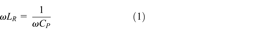
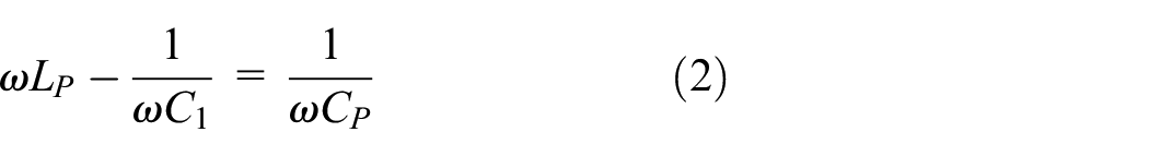

The equivalent impedance of the receiving side is:

The reflected impedance of the receiving side to the primary side Z r can be obtained as:

During resonance, Z r and Z s are substituted as follows, the fundamental part of the equivalent impedance of the primary side is:

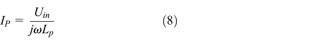
The primary input current I R can be obtained as:
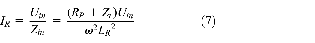
According to the parallel shunt principle, the current through the inductor L P is calculated as follows
The current of the secondary side is affected by the current of the primary side and its own impedance, and the current I s is expressed as

The power output by the system can be represented by the secondary current and equivalent impedance together
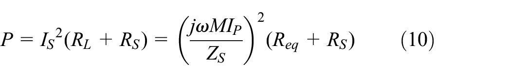
The above is the mathematical model analysis of LCC-S topology. From equation (8), it can be seen that the current flowing through the primary side inductor LP only depends on the angular frequency ω and Uin, this indicates that the current anti-interference performance of the LCC-S topology primary coil is strong, and it is not affected by external and secondary circuit parameter changes. This is also the reason why the high-order compensation topology has better performance compared to the low-order compensation topology. Therefore, the LCC-S topology will be adopted. In addition, from equation (10), it can be seen that changes in mutual inductance will directly affect the output power of the system. In order to effectively reduce the changes caused by mutual inductance, it is necessary to identify the mutual inductance parameters.
Principle of parameter identification
Parameter identification is essentially the process of determining a reference model that can replicate the behavior of the real model based on input and output data. In Figure 3, the primary output currents I R and I R ′ of the real model and reference model are selected as the recognition models, and then the root mean square (rms) operation is used to calculate the error between I R and I R ′. Afterwards, the error is fed back to the mutual inductance identification algorithm and closed-loop control is carried out until the error between the identification model and the actual model reaches the minimum or the iteration number reaches the maximum. If the error between these two models can reach very small (within the expected range), it indicates that the selected recognition model can highly fit the actual model; If the error between these two models is relatively large, it indicates that the selected identification model cannot highly fit the actual model, and therefore cannot replace the actual model for mutual inductance identification.

Schematic diagram of mutual inductance parameter identification.
Improved PSO algorithm for mutual inductance identification
Conventional PSO algorithm for parameter identification
From the mathematical model analysis in chapter “Improved PSO algorithm for mutual inductance identification,” it can be seen that the mutual inductance of the system directly affects the output power of the system. If real-time monitoring of mutual inductance is not possible, then when mutual inductance changes, the transmission performance of the system will be seriously affected. Therefore, identifying the mutual inductance quickly and accurately is necessary, which can provide real-time data for the later control of the WPT system.
Some optimization algorithms, such as PSO algorithm, 38 gray Wolf optimization (GWO) algorithm39–41 have been applied to gain the optimal parameters in various control systems.
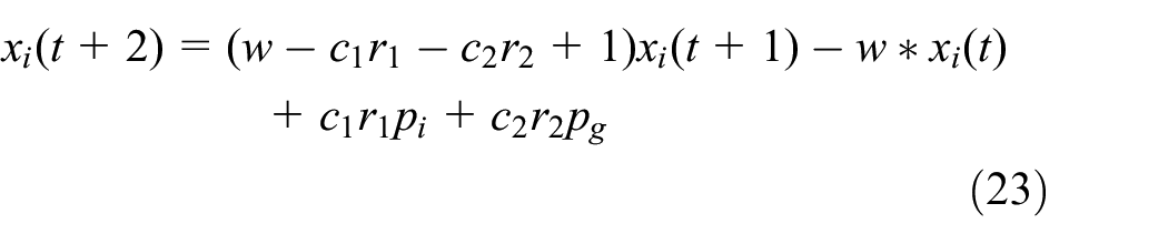
In the PSO algorithm, the velocity and position of each particle is:
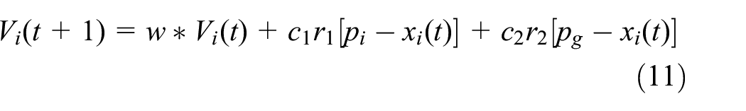

In the above formula, r1 and r2 are any random numbers between [0,1], c1 and c2 are two acceleration factors, and w is the inertia weight. p i represents the individual optimal value for each particle, and p g represents the optimal value for the whole populations.
It can be deduced from the previous formula that the rms value


According to equations (13) and (14), the real primary current is:

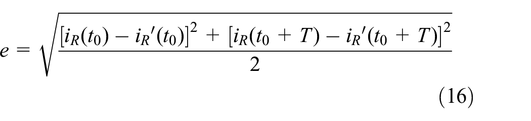
The mutual inductance identification process using the PSO algorithm is shown in Figure 4. The parameters are set as follows: the number of populations N is 200, the number of iterations is 100, and the range of mutual inductance is between [0, 30 μH]. Subsequently, collecting I R , and calculating the fitness value e for the whole particles. The fitness function e is the error between I R and I R ′:
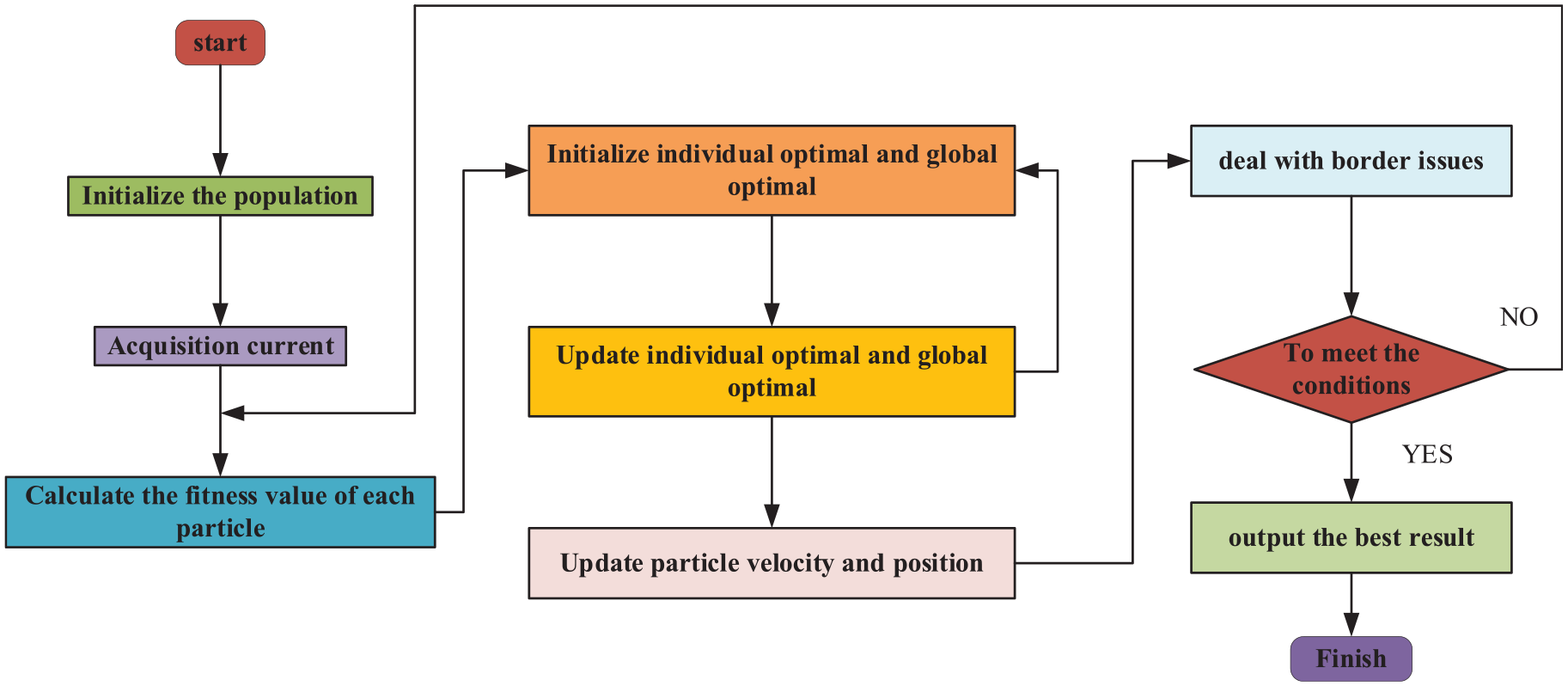
Conventional PSO algorithm for identifying mutual inductance.
In the fitness function formula, t0 is the startup time of the system, and t0 + T is next cycle. I R and I R (t0 + T) represent the actual value of the primary current at t0 and t0 + T; IR′ and IR′(t0 + T) represent the reference value of the primary current at t0 and t0 + T.
Comparing e(i) with p i . If e(i) < p i , replace p i , with e(i) and update p i . Then comparing e(i) with p g , if e(i) < p g , replace p g with e(i) and update p g .
Setting boundary conditions for particles based on velocity and position of particles:

Among them, in the boundary conditions, w M is the maximum value of w, w m is the minimum value of w, G is the maximum iterations number, and g is the current iteration number.
If the iterations number reaches w M , the algorithm will end and the optimal result is obtained; otherwise, the algorithm will continue.
Improved PSO algorithm for parameter identification
For conventional PSO algorithm, the particles have drawback of susceptibility to falling into local optimum. To avoid this condition, the particles should have the characteristic of changing their trajectory on their own. To realize this goal, an improved velocity update equation with adaptive variable detection vector is proposed. At this point, the velocity of the particles can be improved as:

R(t) can be expressed as:
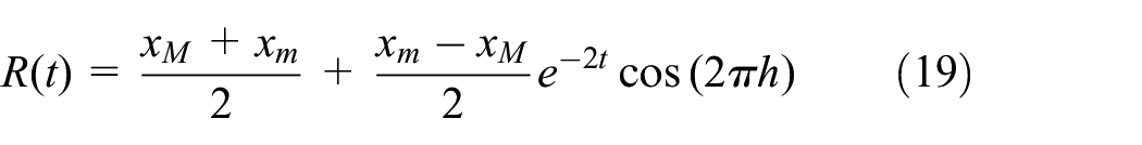
Where h in the formula is a random variable between 0 and 1, x M and x m are the greater and smallest value of x, and t is iterations number.
Through the improvement, the direction and magnitude of particle velocities are changed. The adaptive radius is added to make the search radius of particles larger, and also expand the search range.
It can be obtained from equations (11) and (12):


Substitute equations (12) and (20) into equation (21) to get:

Further simplification of equation (22) can be obtained:
Continue to adjust the order of the formulas to get a second-order constant coefficient inhomogeneous difference equation:

To avoid the defect of falling into local optimum, a velocity reset equation is added, which can be expressed as:


In the above formula, Vrand represents a randomly generated velocity update matrix in a given velocity range [−V m , V m ]. λ is a linear decreasing coefficient, iter M is the largest algebra, and iter c is the current algebra. rw is a correlation coefficient, similar to the inertia coefficient and rw M is the maximum value, rw m is the minimum value.
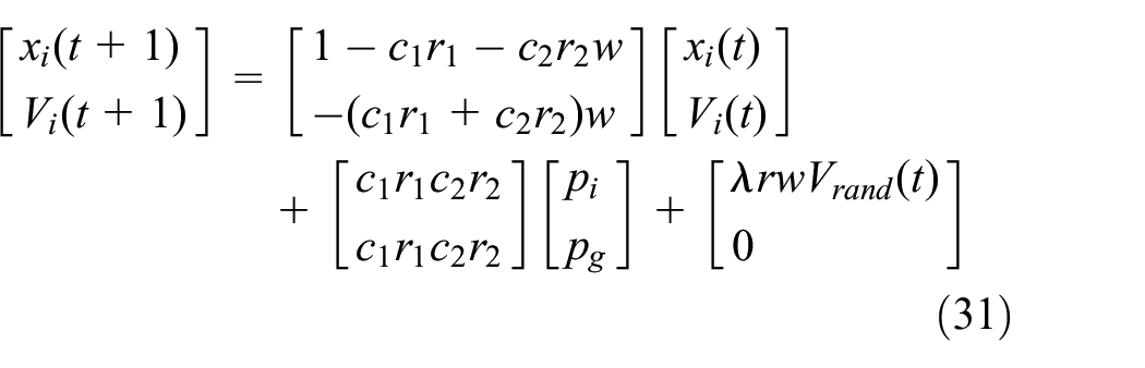
For the improved PSO algorithm proposed above, the formulas are sorted and replaced firstly, then, the equations are rewritten. Finally, the improved velocity and position equations are updated as:


Substitute the speed reset equation into the activation, and rewrite the above equation to get the new equation:

Simultaneous equations (29) and (30) to get a new matrix equation:
Further, the following formula is derived:


Rewrite equations (31) to (34) and equation (35):

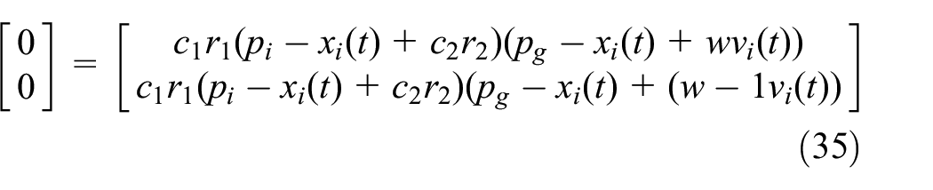
If and only if
The mutual inductance identification process using the improved PSO algorithm is shown in Figure 5.
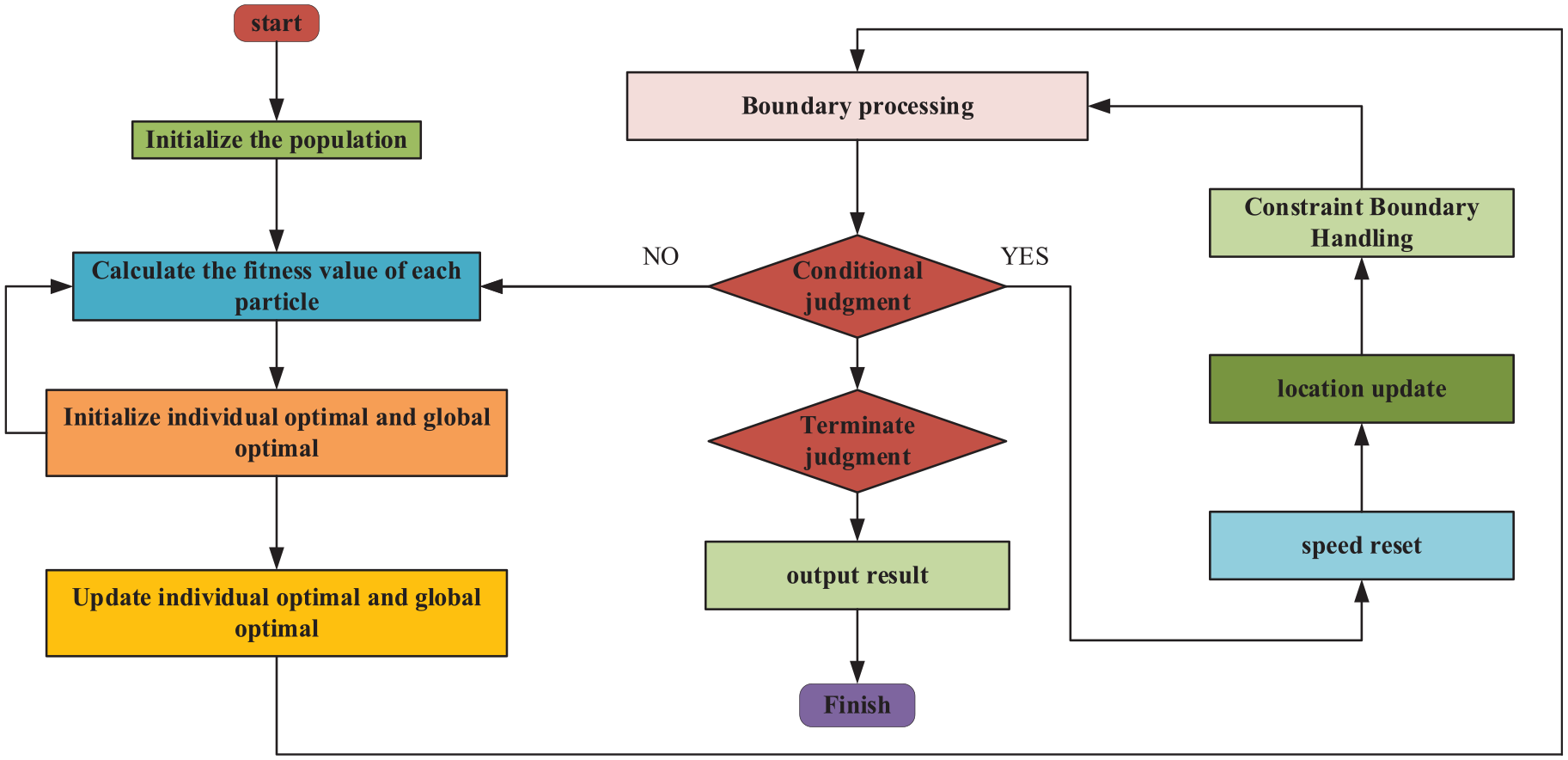
Improved PSO algorithm for identifying mutual inductance.
Simulated analysis
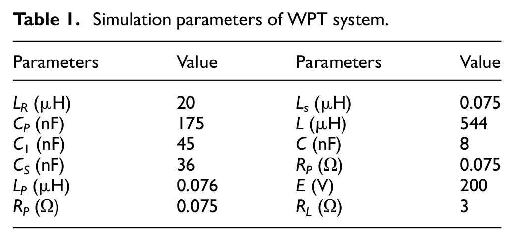
In order to analyze the performance of the improved PSO algorithm, MATLAB simulation software was used to test its performance. Table 1 lists the system parameters used in the simulation process.
Simulation parameters of WPT system.
Output result of inverter circuit
The output voltage of the inverter circuit is shown in Figure 6. After stabilization, the output voltage exhibits an amplitude of 25 V, forming a square wave. The output current of the inverter circuit is shown in Figure 7, the current approximates sinusoidal alternating current, with an amplitude of 80 A.
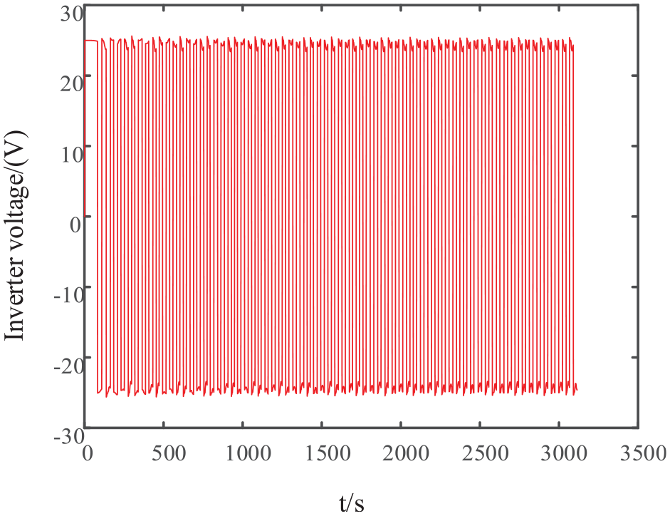
The voltage simulation diagram of the inverter circuit.

The current simulation diagram of the inverter circuit.
Output result of resonant circuit
After DC–AC process, the alternating current will be transferred to the secondary side of the system through magnetic coupling. Therefore, the resonant circuit is inevitable.
Figure 8 represents the output voltage of the resonant circuit. After stabilization, the output voltage exhibits an amplitude of 20 V, forming a sinusoidal wave. The output current of the resonant circuit is shown in Figure 9, the current approximates sinusoidal alternating current, with an amplitude of 55 A.

The voltage simulation diagram of the result of the resonant circuit.

The current simulation diagram of the result of the resonant circuit.
From the output results of the inverter circuit and resonant circuit, it can conclude that the most electrical energy in the primary of the system can be transferred to the secondary side. Because of the leakage inductance, a little electrical energy will be dissipated in the air.
Simulation comparison of two algorithms with constant mutual inductance
The simulation parameters were set: mutual inductance is 28.24 μH, the supply voltage is 50 V, the load is 20 Ω. Then, the WPT system can operate. After stabilization, two current points separated by one cycle were collected as test data. These data points were then fed into the two algorithms for iterative optimization. The improved PSO algorithm was compared with the conventional PSO under identical conditions. Figure 10 presents a comparison of the two algorithms in optimizing the error function e during the process of mutual inductance identification.
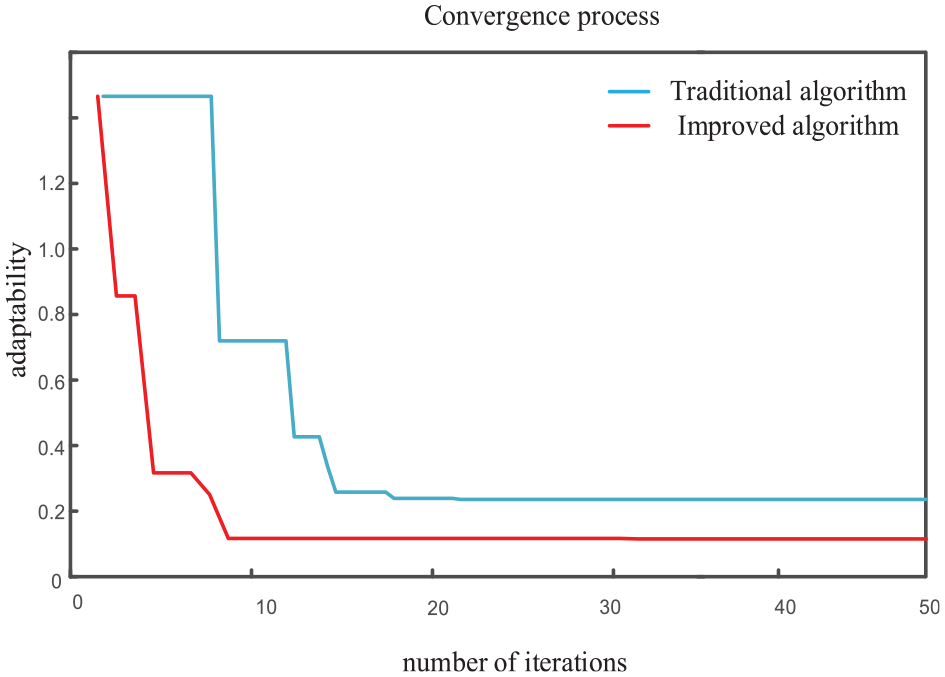
Error function optimization process under the comparison of two algorithms.
It can be seen from Figure 10 that the PSO algorithm stabilizes in the 20th generation. The final identification mutual value of mutual inductance is 28.16 μH, and the relative error is 0.28%. The improved PSO algorithm stabilizes in the eigth generation. The final identification value of mutual inductance is 28.19 μH, and the relative error is 0.17%.
In order to further verify whether the system can perform correct mutual inductance identification when the load changes. Keeping the mutual inductance article unchanged and obtaining the identification results in Tables 2 and 3 through multiple simulations (Here, the conventional PSO algorithm is simplified as CPSO, and the improved PSO algorithm is simplified as IPSO).
Identification data of mutual inductance parameters optimized by CPSO under load change.

Identification data of mutual inductance parameters optimized by improved IPSO under load change.
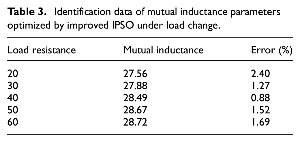
According to the simulation results in Tables 2 and 3, it can be seen that the order of identification accuracy is not necessarily related to the order of load resistance. Under CPSO algorithm, when the load is 40 Ω, the identification accuracy is highest with an error rate of 1.84%; When the load is 20 Ω, the identification accuracy is the lowest with an error rate of 2.93%. Under IPSO algorithm, when the load is 40 Ω, the identification accuracy is highest with an error rate of 0.88%; When the load is 20 Ω, the identification accuracy is the lowest with an error rate of 2.40%. In addition, through overall observation, it can be concluded that the identification accuracy of IPSO is higher than that of CPSO, indicating that the IPSO algorithm has stronger search ability and better optimization performance. In order to clearly demonstrate the difference between CPSO algorithm and IPSO algorithm in identifying mutual inductance, the identification value and the actual value of mutual inductance are compared, which are shown in Figures 11 and 12.

Corresponding mutual inductance under different loads with conventional CPSO algorithm.

Corresponding mutual inductance under different loads with improved IPSO algorithm.
Simulation comparison of two algorithms for mutual inductance variation
Due to the installation of non-contact excitation motors on electric vehicles, the violent movement of the tram inevitably causes displacement between the stator and rotor, which will also change M between the coupling coils. Therefore, we simulate the coil offset between the stator and rotor by manually adjusting the position between the coupling coils.
Set the simulation time to 3 ms and the simulation step size to 12 μs, M is 35.23 μH. The voltage supply is 50 V, and the load is 20 Ω. Waiting until the system runs stably and collect two current points separated by one cycle as test data. Then, it is passed on to PSO algorithms and improved PSO algorithms for iterative optimization. Figure 13 shows a comparison of the optimization process of the error function e in mutual inductance identification between two algorithms.

Error function optimization process under the comparison of two algorithms.
Through the comparison between the two algorithms, it can be seen that the PSO algorithm stabilizes in the 19th generation, and the value of identified M is 34.79 μH, and the error rate is 1.24%. The improved PSO algorithm stabilizes in the 16th generation, and the value of identified M is 35.01 μH, and the error rate is 0.62%.
By comparing Figures 13 and 10, it can conclude that even in the case of changes in mutual inductance, the proposed optimization algorithm can still achieve high-precision recognition, and compared to the PSO algorithm, this improved algorithm has higher recognition accuracy. Therefore, it can be inferred that within a certain range of mutual inductance changes, the proposed identification algorithm can achieve high-precision recognition, so that the non-contact excitation system can adapt to road load conditions.
Experimental verification
The WPT experiment equipment is shown in Figure 14, and the equipment includes DC power supply, inverter circuit, resonant circuit, rectifier circuit, DSP28335 development board, and computer.

WPT Experimental Platform.
Verify the influence of the mutual inductance value predicted by the system and the actual measured mutual inductance value when the load is determined and the mutual inductance changes. Set the load as a constant value and compare the mutual inductance value of the identification algorithm with the actual measured mutual inductance value. Make intuitive analysis of tables and images. Setting the offset distance to 1 cm, then identify the mutual inductance value and compare the calculated error with the actual measured mutual inductance value.
Figure 15 shows the working status of four MOSFETs in the inverter circuit. Among them, the conduction PWM signals of MOSFET 1 and 3 are the same, while MOSFET 2 and 4 are the same. Figure 16 shows the voltage square wave output by the full-bridge inverter circuit. By adding a resonant circuit, the square wave voltage can generate sinusoidal alternating current. The primary side is an LCC resonant circuit. The sinusoidal alternating current resonates in the resonant circuit, making the primary side resonates, and the electric energy is transferred to the secondary side series resonant circuit through magnetic coupling. At the same time, the frequency of the generated alternating current can also meet the design parameter requirements.

Four-way PWM waveform of MOSFETs tube.

The inverter circuit outputs a square wave voltage.
In order to make the identification result more reasonable, the experiment also studied the occurrence of lateral and longitudinal offsets between magnetic coupler. Table 4 shows the mutual inductance identification result when the coupler undergoes lateral offset, and Table 5 shows the mutual inductance identification result when the coupler undergoes longitudinal offset. The line graphs in Figures 17 and 18 provide a more intuitive representation of these two tables.
Identification value and actual value of mutual inductance under lateral offset.

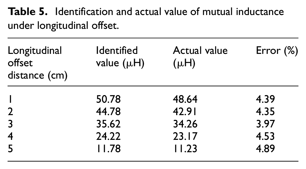
Identification and actual value of mutual inductance under longitudinal offset.

Comparison of identification value and actual value of mutual inductance under lateral offset.
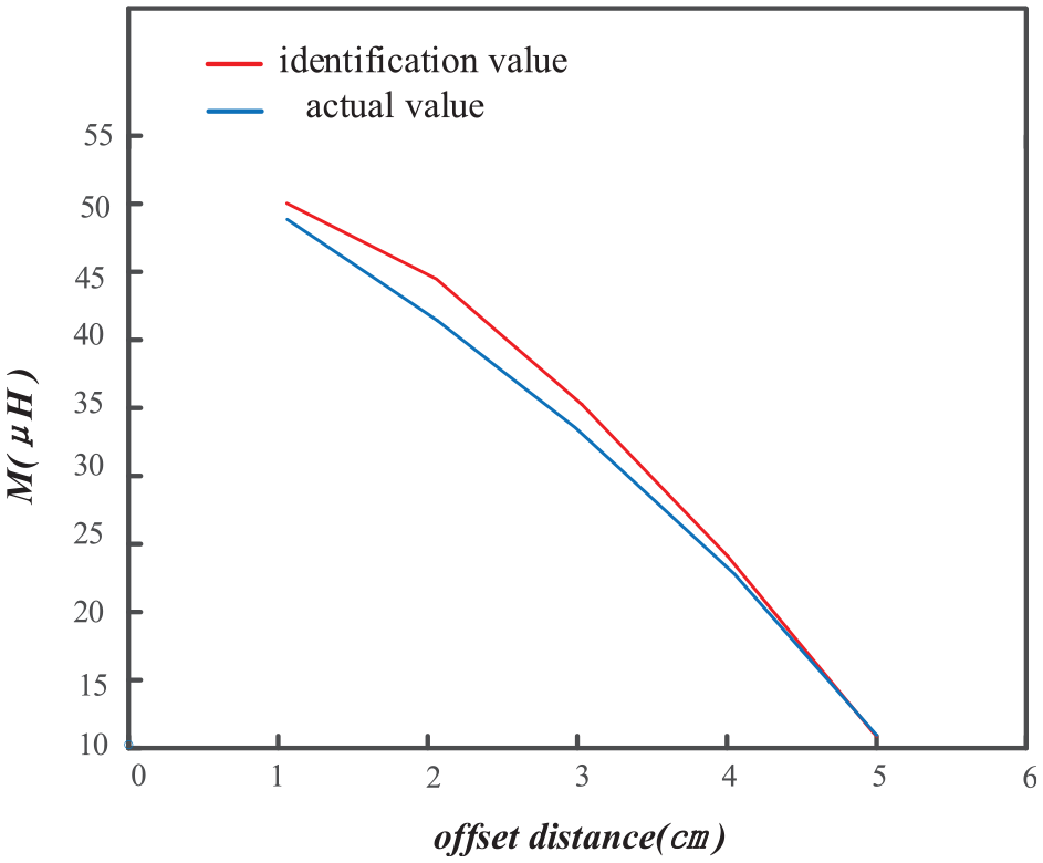
Comparison of identification value and actual value of mutual inductance under longitudinal offset.
Comparing the identification value with the actual measured value, and finding the error of the two, it is found that the error can be guaranteed to be 4%, because this article does not consider the parasitic parameters of circuit, so the error is acceptable. These errors mainly come from the loss in the equipment. In addition, due to the energy transfer through the magnetically coupled resonant coil, there will still be magnetic flux leakage between coupling coil.
From the experimental result in Tables 4 and 5, it can be seen that the offset between the coupling coils will decrease the identification accuracy. For lateral offset, the identification accuracy is the lowest when the offset distance is 1 cm, with an error rate of 5.25%; The identification accuracy is highest when the offset distance is 4 cm, with an error rate of 3.19%. For vertical offset, the identification accuracy is the lowest when the offset distance is 5 cm, with an error rate of 4.89%; the identification accuracy is highest when the offset distance is 3 cm, with an error rate of 3.97%. Furthermore, from the experimental result, it can be seen that there is no necessary correlation between the identification accuracy and the size of the offset distance.
Conclusion
This article mainly analyzes the characteristics of a Non-contact excitation system based on WPT and proposes an improved PSO algorithm for identifying mutual inductance of the system. Specifically, it includes the following aspects:
In response to a series of drawbacks of the brush excitation method for EESM, this article proposes a non-contact brushless excitation system based on WPT technology. Regarding the core technology of the system—WPT, this article focuses on studying its transmission characteristics and the factors that affect its output power.
In response to the direct impact of mutual inductance on the transmission power of the system, this article proposes an improved PSO algorithm for identifying mutual inductance, which can lay the foundation for system control.
When the system is applied to electrical vehicles, it is inevitable to encounter situations where the road conditions are very poor, which will result in uncertain changes of mutual inductance. Considering this situation, research is conducted on the lateral and vertical offsets of the coupling coils in the experimental section, and an improved PSO algorithm was used to identify the changing mutual inductance values. According to the experimental, it can be seen that the identification error rate of this algorithm can be basically maintained below 5% under various deviations of the coupling coils, which meets the expected requirements.
Footnotes
Handling Editor: Yawen Wang
Declaration of conflicting interests
The author(s) declared no potential conflicts of interest with respect to the research, authorship, and/or publication of this article.
Funding
The author(s) received no financial support for the research, authorship, and/or publication of this article.