
Abstract
Based on the mechanistic model of the two-phase swirling annular flow behavior, a calculation method for the effective distance of vortex tool is obtained by taking Kelvin–Helmholtz instability into account. The rationality of the proposed method is validated by comparing the predicted liquid film thickness and pressure under non-swirling flow with the commonly used correlations. Then, the influences of gas–liquid ratio, helix angle, and hub diameter of vortex tool on the liquid film thickness, pressure drop, and effective distance have been analyzed. Results show that the presence of the vortex tool causes the decrease in the liquid film thickness and increase in the pressure drop. The liquid film thickness increases gradually as the helix angle and the hub diameter increase, and the larger helix angle results in smaller pressure drop. The effective distance increases with an increase in the gas–liquid ratio and decreases with an increase in helix angle and hub diameter. A sudden decrease occurs when the helix angle exceeds 60°. The gas–liquid ratio and helix angle are more dominant factors than the hub diameter on the liquid film thickness, pressure drop, and effective distance.
Keywords
Introduction
Swirl flows have a variety of applications in the oil and gas industry, such as in casing turbulators, 1 rotary gas separators, 2 and vortex tools, 3 due to good separating properties and conveyance performance. The vortex tool is a newly developed downhole equipment to unload liquid and restore continuous production of low-rate gas wells. At present, the commonly used vortex tool consists of a fishing head, a corkscrew deflector, a draft tube, and the setting device, as shown in Figure 1. It has no moving parts and does not need additional energy source. Field tests and laboratory experiments3,4,5 revealed that the vortex tool was able to lower the critical gas velocity, reduce the tubing pressure loss, and improve the liquid-carrying capacity of gas wells.

Structural diagram of the vortex tool.
When the fluid flows through the annular channel between the corkscrew deflector and the tubing, the flow pattern is transformed from straight flow to swirling flow due to the centrifugal force, and the swirling flow will propagate over a long distance. However, due to the wall friction in the downstream of the vortex tool, the swirling flow will gradually decay and revert back to the upstream straight flow. The work by Kreith and Sonju 6 showed that a turbulent swirl decays to about 10%–20% of its initial intensity in a distance of about 50 pipe diameters. And recently, Liu and Bai 7 have conducted experimental investigations to study the decay of the gas–liquid two-phase swirling flow. The results showed that the gas–liquid two-phase swirling flow decays quickly and the swirl intensity reduces to 1% of the initial swirl intensity at about 30 pipe diameters. Obviously, the decay of swirling flow is inevitable. Therefore, numerous researchers have studied the decay rate of the swirling flow. To summarize, the decay of the swirling flow is best fitted by an exponential law, 8 and the decay rate is mainly affected by the pipe roughness, 9 the Reynolds number, 10 the geometry of the swirler, and the initial swirl intensity. 11
So, it is an alternative method to increase the effective swirl distance by optimizing the geometrical configuration of vortex tool to reduce the swirl intensity decay rate. In addition, a more effective way is to install multiple vortex tools along the tubing to maintain the continuity of the swirling flow. Table 1 shows the stages and installation depth of vortex tools in partial gas wells in China.
Statistics of vortex tool stages and installation depth.

As shown, the given five test wells are equipped with multiple stages of vortex tools. In wells S14-11-38, S6-16-25, C45, and S-5, the vortex tools are almost equally spaced, and the distance between adjacent vortex tools in well B1-9 increases upward along the tubing. The minimum spacing is 770 m and the maximum spacing is 1775 m, which are much greater than the swirl distance obtained from the swirl intensity decay theory. Obviously, the spacings given in Table 1 are not the true swirl distances of the vortex tools. Therefore, it is of great significance to investigate the effective swirl distance of vortex tool theoretically. Unfortunately, works addressing these problems directly are rare in the literature.
Chen et al. 16 studied the decay law of swirl flow induced by vortex tools numerically and defined the effective swirl distance as the length from the export of the tool to the point where swirl intensity equaled zero. The numerical results indicated that the effective distance of vortex tool is in the range of 10–100 m, and the inlet velocity and gas–liquid ratio (GLR) are the main influencing factors. In the early 1990s, Wells and Smith 1 investigated the effects of flow rate, viscosity, density, and turbulator blade geometry on the effective distance of the swirl flow produced by casing turbulators numerically and experimentally. In his work, the effective swirl distance was defined as the axial distance along the casing annulus where the flow angle remained greater than 3° from on-axis. Results showed that the effective swirl distance increased with an increase in turbulator blade angle and flow rate. Shu and Luo 17 obtained the attenuation regularity of swirl flow induced by casing turbulators through experimental simulation and established a calculation formula for the installation space of turbulators on the basis of force balance analysis.
In addition, several investigators have studied the effective distance of vortex generator. The work by Eibeck and Eaton 18 revealed that in a rectangular straight channel, the continuous distance of the longitudinal vortex can be approximately 100 times as long as the height of the vortex generator. Through numerical simulation, Wang et al. 19 suggested that in a narrow rectangular straight channel, the reference value of the longitudinal spacing of the vortex generator is 30–45 times the thickness of the channel gap. Zhang et al. 20 studied the effect of curvature and Reynolds number on the effective distance of vortex generator numerically and found that the effective distance of the vortex generator increased with a decrease in curvature and an increase of Reynolds number. It can reach 79 times the height of the vortex generator with the curvature of 0.05, attack angle of 10°, and Reynolds number of 5370.
In order to study the effective swirl distance, the effective swirl time can be studied first. Hoffmann and Stein 21 studied the liquid film residence time in the gas–liquid cyclone theoretically. Assuming that all of the liquid was gathered at the wall of the cyclone to form the liquid film under the impact of the centrifugal force, he derived a theoretical liquid film residence time calculation model based on the force balance on the gas and liquid phase in the axial direction. To verify the accuracy of the Hoffmann model, Yang et al. 22 performed a cold model experiment to investigate the average liquid film residence time in a gas–liquid cyclone using a holdup method. The experimental results showed that the liquid residence time obviously decreased with an increase in inlet liquid holdup and decreased less with an increase in inlet gas velocity. And the predicted residence times by Hoffmann model were in good agreement overall with the measured values. However, the predicted residence times were higher than the measured values within the liquid film Reynolds number smaller than 1200.
The main objective of this study is to establish a prediction model of the swirling annular flow behavior induced by the vortex tool based on the force balance of liquid film, and then derive a calculation method for the effective distance of interfacial disturbance wave, in which the Kelvin–Helmholtz (KH) instability was taken into account. Moreover, the influences of GLR, helix angle, and hub diameter of vortex tool on the liquid film thickness, pressure drop, and effective distance are investigated.
Theoretical analysis of the swirling annular flow
After the downhole fluids flow through the vortex tool, the heavier liquid will gather toward the pipe wall to form a liquid film under the impact of the centrifugal force, while the lighter gas is centered to form a gas core. Therefore, the gas–liquid two-phase flow pattern is transformed to the swirling annular flow. In this study, to simplify the analysis, the gas–liquid two-phase swirling annular flow is decomposed into an axial annular flow and a tangential circular motion. By analyzing the axial force characteristics of annular flow, a mechanism model is established.
Force balance analysis
Assuming that all of the liquid in the pipe flows along the wall in the form of a uniformly thin film, as shown in Figure 2, the force balance on the liquid phase is 23

and that on the gas phase is


Schematic of force balance in the axial annular flow.
Suppose that ε is the gas void fraction, the perimeter and cross-sectional area of liquid film and gas core can be expressed as


When the liquid film is in equilibrium with the air core, we can get the following new correlation with equations (1)–(6) by eliminating the pressure gradient

According to the annular theory by Wallis, 24 the axial shear force between the liquid film and the pipe wall can be written as

Similarly, the axial shear force between the liquid film and the gas core can be expressed as
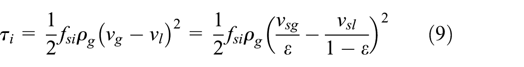
where fsw and fsi are the wall friction factor and interfacial friction factor in the swirling field, respectively. However, no prior study has been performed to evaluate the friction factor of swirling flow induced by the vortex tools. Considering the similarity between the twisted tape and the guide vane of vortex tool, the friction factor calculation method developed from the twisted tape is introduced here. Gambill et al. 25 believed that the twisted tape increased the frictional surface area of the fluid, resulting in the swirl flow friction coefficient being greater than that of the straight pipe axial flow. The following correlation was established

where fs and f are the friction factor in the pipe with and without twisted tape, and y is the twist ratio defined as the ratio between the tape turn length of 180° along its axis and the tube diameter

Lopina and Bergles 26 also performed an experimental study of the friction factor inside tubes with twisted tape and found that the Gambill correlation was not suitable for the smooth tube systems. Thus, a correlation for smooth tube was given

According to equation (12), it can be concluded that the predicted swirling flow friction factors are less than those of the non-swirl axial flow if the twist ratio is above a certain lever. Therefore, Jensen et al. 27 recommended that the Gambill correlation was used for the twist ratio greater than 11.25, and Lopina–Bergles correlation was used for the twist ratio less than 11.25. In this study, Jensen’s recommendation is applied. For the vortex tool, the following relationship exists between the helix angle, pitch, and pitch diameter of the guide vane
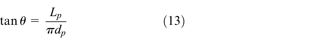
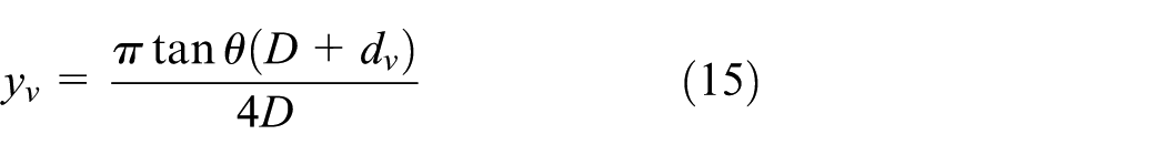
where the helix angle θ is defined as the angle of guide vane with respect to the horizontal direction. The pitch diameter can be written as

Substituting equations (13) and (14) into equation (11), the twist ratio of vortex tool can be obtained
According to equations (10) and (12), in order to calculate the friction factor for the pipe with vortex tool, the friction factor for empty pipe is needed. Here, the correlation of Ouyang et al. 28 is used to calculate the wall friction factor fw, given as

where Ref is the liquid film Reynolds number. The following expression based on Wallis 24 is used for evaluating the interfacial friction factor fi
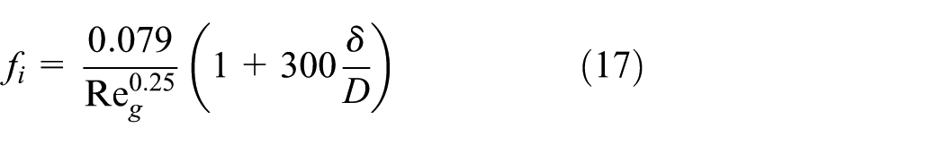
For thin films in the pipe, equation (17) can be approximated to

By combining equations (7)–(18), we can get an implicit expression of the gas void fraction. After iteratively solving the gas void fraction, the liquid film thickness, gas and liquid velocity, and pressure drop can be obtained.
Effective swirl distance of vortex tool
In this section, the KH instability theory is applied to analyze the development of liquid film in the gas–liquid two-phase swirling flow field in the downstream of the vortex tool. According to Chandrasekhar, 29 when two fluids flow relatively along the interface, the KH instability occurs due to the existence of a velocity shear layer between two fluids. Therefore, there must be KH instability between the gas–liquid interfaces for the annular flow. In Berna et al.’s 30 study, the liquid film in annular flow is considered to be composed of two parts: a thick, fast-moving disturbance wave and a thin, slow-moving base film, as shown in Figure 3.
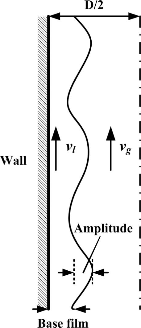
Schematic of the disturbance wave.
Just as the harmonic amplitude evolves with respect to the distance to the excited base, 31 the disturbance wave at the fluid interface grows linearly and weakly nonlinearly and eventually develops into a turbulent mixture with the development of the annular flow. According to the instability theory, the disturbance amplitude in the linear phase increases exponentially. So, the disturbance amplitude can be expressed as

where a0 is the disturbance wave amplitude at the initial time and κ is the perturbation linear growth rate. According to Chandrasekhar 29 and Wang et al., 32 the perturbation linear growth rate in the classical KH instability is
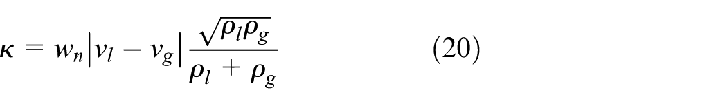
In equation (20), the disturbance wave number wn can be calculated by the following equation
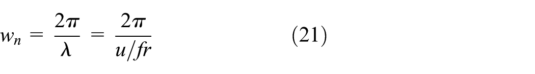
where λ represents the disturbance wavelength, u represents the disturbance wave velocity, and fr represents the disturbance wave frequency. With respect to the disturbance wave velocity and frequency, several researchers have proposed the corresponding correlations. In this study, the Kumar et al. 33 model is used to calculate the disturbance wave velocity. Assuming that the interfacial friction factors based on the gas velocity and liquid velocity are equaled, Kumar presented the wave velocity by the following expression

where ψ can be obtained from the following empirical correlation

And the Sekoguchi 34 model is applied to estimate the wave frequency, given by

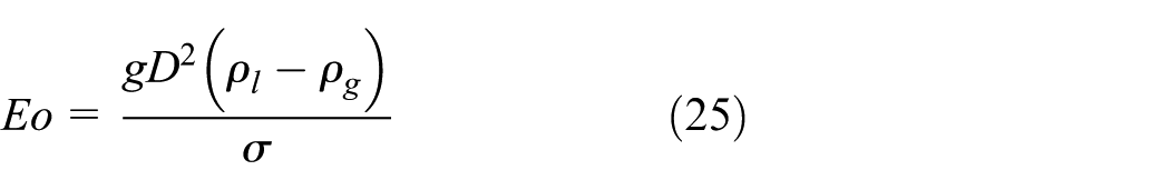
where Eo is the Bond number and Frg is the Froude number, defined, respectively, as follows

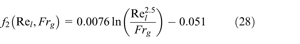
Through regression analysis of the experimental data, Sekoguchi 34 obtained the empirical expressions for f1 and f2, which can be written as

Obviously, the perturbation linear growth rate κ can be obtained by combining equations (20)–(28) once the gas and liquid velocity are solved from the previous section. According to equation (19), in order to get the duration time of disturbance wave, the wave amplitude must be determined first. As mentioned before, the swirling flow eventually reverts back to the upstream straight flow as the swirl intensity decays. The liquid film on the pipe wall will be dispersed in the gas phase as droplets again with the development of disturbance wave. Sawant et al., 35 Berna et al. 30 and Pan et al. 36 think that the disturbance wave is a necessary condition for the entrainment of droplets from the wavy interfaces. Therefore, it can be considered that the final disturbance amplitude is equal to the inner diameter of the pipe (a≈D) when the swirling flow transformed to the straight flow. The initial disturbance amplitude (a0) can be calculated by the Han model 37

After the duration time of the disturbance wave is obtained, the effective distance of the disturbance wave (effective swirl distance) can be approximately estimated by the following formula

where vsm is the average velocity of the gas–liquid mixture and ts is the duration time of the disturbance wave. The average velocity of the gas–liquid mixture can be written as

Results and discussions
Liquid film thickness
In order to verify the reliability of the newly proposed method in this article, a comparison with the commonly used liquid film thickness correlations has been made. The typical conditions for comparison are taken from a real gas well (well C45) and the parameters needed are shown in Table 2. The gas deviation factor and viscosity are estimated by Dranchuk–Purvis–Robinson 38 method and Lee–Gonzalez–Eakin 39 method, respectively. It should be noted that the existing correlations proposed by Tatterson et al., 40 Fukano and Furukawa, 41 Okawa et al., 42 Berna et al., 30 and Pan et al. 36 are all established based on the non-swirling two-phase gas–liquid flow. Therefore, for the sake of consistency, the wall friction factor and interfacial friction factor under non-swirling flow are used when using the new proposed method to calculate the liquid film thickness.
Basic parameters of well C45.

Figure 4 displays the liquid film thickness predicted by various models under different gas rates. As shown, the predicted liquid film thickness decreases with an increase in gas rate (gas superficial velocity) at a given water rate (water superficial velocity). Moreover, compared with the proposed method in this article, the predicted values of other empirical models under high pressure (7.13 MPa) change marginally with the gas superficial velocity. In addition, the predicted values by the new method are close to the Pan’s correlation when the gas superficial velocity is greater than 1.2 m/s. In Figure 4(b), the predicted liquid film thicknesses by the new method are in good agreement with Berna’s correlation under low pressure (0.2 MPa). From the above analysis, it can be concluded that there is no order of magnitude difference in the liquid film thickness predicted by the new method and the commonly used correlations, which explains to some extent the rationality of the new method in the calculation of liquid film thickness.
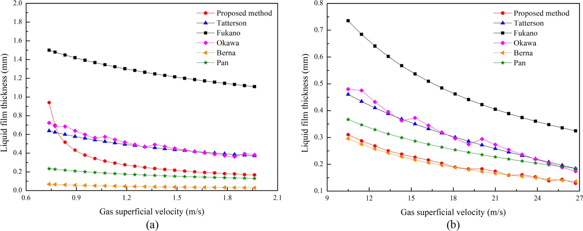
Comparison of liquid film thickness predicted by different correlations: (a) P = 7.13 MPa, vsl = 0.004 m/s and(b) P = 0.2 MPa, vsl = 0.01 m/s.
To further investigate the difference in liquid film thickness under swirling and non-swirling flow, the film thicknesses in the downstream of vortex tools with different helix angles and hub diameters are compared with those without vortex tool, as shown in Figure 5. It is obvious that the liquid film thickness decreased after the installation of vortex tool. This demonstrates that the liquid-carrying capacity of gas is enhanced in the swirling flow field. The increase in the drag force of the air core on the liquid film leads to more liquid phase being dispersed in the air core in the form of droplets. Moreover, the reduction of the liquid film thickness is greater at lower gas flow rates. So a more pronounced effect can be achieved to use the vortex tool at a low gas flow rate.
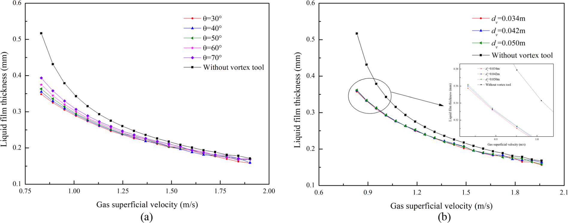
Effects of the structure parameters of vortex tool on the liquid film thickness: (a) helix angle and (b) hub diameter.
The results in Figure 5 also show that the larger the helix angle and the hub diameter, the larger the liquid film thickness. The liquid film thickness increases more with an increasing helix angle than with an increasing hub diameter, which means the helix angles have a more dominant effect on the liquid film thickness than hub diameters. The results in respect to liquid film thickness are in good agreement with the experimental results of Takeshima et al. 43 and numerical results of Park and Chang. 44 The investigations on gas–liquid two-phase flow characteristics in a helical wire inserted tube by Takeshima and Park demonstrated that the average liquid film thickness increased as the pitch length and the inserted wire diameter increased. Therefore, priority should be given to the helix angle when designing vortex tools. And the liquid-carrying capacity of the vortex tool can be improved by reducing the helix angle.
Pressure drop
The proposed model can also be applied to predict the pressure distribution under annular flow conditions. Figure 6 shows the comparison of wellbore pressure distribution of well C45 predicted by the new model and six commonly used empirical correlations.45–50 The calculation results are obtained without vortex tool. The depth of well C45 is 2400 m. As can be seen, the pressure values predicted by the proposed method are between the Mukherjee and Brill model and the Hagedorn and Brown model and have better consistency with the Hagedorn and Brown model. According to the study by Zhou et al., 51 the Hagedorn and Brown model has higher accuracy when calculating wellbore pressure. Therefore, the proposed model is reliable in the calculation of pressure drop.

Comparison of pressure distribution predicted by available correlations.
In addition to the gas–liquid two-phase axial flow, the pressure drop in swirling flow can also be calculated. Figure 7 illustrates results that the helix angle affects the pressure drop in swirling flow induced by the vortex tool. The pressure drop at five helix angles were obtained with the gas superficial velocity varying from 0.9 to 1.5 m/s at a constant water superficial velocity of 0.004 m/s, respectively. It shows that the presence of the vortex tool results in an increase in the pressure drop and the pressure drop in the downstream of vortex tool increases with an increase in the gas superficial velocity and decreases with an increase in the helix angle. The pressure drop decreases by 27%–37% with the helix angle increasing from 30° to 70°. That is because the vortex tool with a larger helix angle has a longer pitch and the long pitch can reduce resistance along the way. The effect of helix angle on the pressure drop is in good agreement with the study by Takeshima et al. 43 and Park and Chang. 44

Effects of the helix angle on the pressure drop.
Effective distance of vortex tool and influencing parameters analysis
Similar to the swirl intensity, the effective distance of the vortex tool is related not only to its geometrical configuration but also to the gas and liquid velocities. In this section, the influences of the GLR, helix angle, and hub diameter on the effective distance are analyzed.
Influence of the GLR on the effective distance
The effective distances of vortex tool at 4 different liquid rates and 11 different GLRs have been calculated by the established model, respectively, where the helix angle is 45° and the hub diameter is 42 mm. The GLR ranges from 0.50 × 10⁴ m3/m3 to 1.50 × 10⁴ m3/m3. Figure 8 shows the effective distance varies with the GLR when the liquid rate is 1, 2, 3, and 5 m3/d. As illustrated in Figure 8, the effective distance increases with an increase in GLR at a constant liquid rate, and the increment gradually decreases. However, when the liquid rate reaches a certain level, such as 5 m3/d, the GLR has little effect on the effective distance of the vortex tool. It can also be seen that the effective distance increases with an increase in the liquid rate at a constant GLR, and the effect of the liquid rate on the effective distance decreases with an increase in GLR. Referring to the studies by Kreith and Sonju, 6 Najafi et al., 8 and Rocha et al., 10 the swirl intensity decay rate decreases with an increase in Reynolds number. Therefore, the swirl flow can propagate over a longer distance at higher Reynolds number, which is in agreement with the results of this study. The effective distance of the vortex tool is 2.97–10.36 m (about 48–167 pipe diameters) under the given study conditions, which has a same magnitude as the research of Kreith and Sonju 6 and Liu and Bai. 7 The study by Kreith showed that the turbulent swirl decayed to about 10%–20% of its initial intensity in a distance of about 50 pipe diameters, while Liu found that the swirl intensity reduced to 1% of the initial swirl intensity at about 30 pipe diameters. Likewise, the results of Shu and Luo 17 indicated that the effective distance of the casing turbulator was generally not more than 10 m.

Effects of the gas–liquid ratio on the effective distance of vortex tool.
Influence of the helix angle and hub diameter on the effective distance
Figure 9 depicts the effective distance of the swirling flow in the downstream of vortex tools with different helix angles at three given GLRs. As illustrated, for a certain GLR, an increase in the helix angle leads to a decrease in the effective distance. The effect of the helix angle on the effective distance is less significant under large GLRs. When the GLR is 1.2 × 10⁴ m3/m3, the effective distance decreases from 9.6 to 8.8 m with the helix angle increasing from 30° to 75°, and the reduction of the effective distance is only 0.8 m.

Effects of the helix angle on the effective distance of vortex tool.
Furthermore, the reduction of the effective distance with the increasing helix angle is not a constant. There is a sudden decrease as the helix angle exceeds 60°. Therefore, it is recommended that the helix angle be controlled within 60° when designing the vortex tool.
Figure 10 shows the variation of effective distance with the hub diameter under different GLRs. It can be seen that for a given GLR, the effective distance decreases approximately linearly with increasing hub diameter. But the reduction is very small. Obviously, the effect of the hub diameter on the effective distance is less significant than the helix angle.

Effects of the hub diameter on the effective distance of vortex tool.
Conclusion
A mechanistic model is established for the prediction of the swirling annular two-phase flow behavior in the downstream of the vortex tool, which is helpful to understand and recognize the difference of the dynamic characteristics of swirling and non-swirling flow. Comparing the liquid film thickness and pressure calculated by the proposed model under non-swirling flow with the commonly used correlations, the rationality of the new model is validated. Combined with the development of the interfacial disturbance wave and taking the KH instability into account, a calculation method for the effective distance of vortex tool is first derived. Once the effective distance of the first-stage vortex tool is determined, the installation position of the next-stage tool can be obtained, which lays the foundation for the determination of the optimal installation position of each vortex tool and the optimal total number of vortex tools. Taking well C45 as an example, the influences of helix angle and hub diameter of vortex tool on the liquid film thickness, pressure drop, and effective distance are investigated.
The presence of the vortex tool results in a decrease in the liquid film thickness and an increase in the pressure drop. But the liquid film thickness increases gradually as the helix angle and the hub diameter increase, and the pressure drop decreases as the helix angle increases. The effect of the helix angle on the liquid film thickness is more significant than the hub diameter, which has good agreement with the experimental results of Takeshima et al. and numerical results of Park et al.
The effective distance increases with an increase in the GLR. Within the scope of the study, the effective distance of the vortex tool is 2.97–10.36 m, approximately 48–167 pipe diameters, which is similar to the analysis results of the swirl intensity decay. However, an increase in the helix angle and hub diameter leads to a decrease in the effective distance. A sudden decrease occurs when the helix angle exceeds 60°.
The GLR and helix angle are more dominant factors than the hub diameter on the liquid film thickness, pressure drop, and effective distance. Therefore, priority should be given to the helix angle when designing vortex tools and the helix angle should not exceed 60°.
Footnotes
Appendix 1
Acknowledgements
The authors would like to appreciate the editors and reviewers for their helpful suggestions.
Handling Editor: Dumitru Baleanu
Declaration of conflicting interests
The author(s) declared no potential conflicts of interest with respect to the research, authorship, and/or publication of this article.
Funding
The author(s) disclosed receipt of the following financial support for the research, authorship, and/or publication of this article: This work was supported by the National Natural Science Foundation of China (grant no. 61572084) and the 13th Five-Year National Major Projects (grant no. 2016ZX05056004002).