
Abstract
In this work, a method is developed for geometric definition and analysis of cylindrical milling tools having various free-form variations of helix angle. The method is based on replicating a position vector on each cutting edge to generate a point set for the whole tool envelope using piece-wise rotation and magnification matrices which are varied according to mathematical laws describing the intended variable shape of the tool. The computed point sets are applied in additive manufacturing of samples of such tools having non-conventional shape features by transforming the point sets to stereolithography formats that are sliced to guide the 3D-printing processes. This manufacturing route that simplifies the realization of arbitrary helix profiles on milling tools is a major contribution of this work since such tools are gaining popularity for their passive damping of vibrations and reduction of cutting forces but are notoriously difficult to manufacture, limiting their exploitation. Analyses are shown about the effects of the considered variable profiles on milling cutting force. These suggest that cutting forces can be greatly suppressed by the proposed free-form helix angle variations. For example, relative to a conventional fixed helix tool of same mean helix angle, the innovative tools recorded 40.33%–84.42% and 60.53%–67.81% force reductions at axial depths of cut of 1 and 5 mm. This demonstrates that innovative variable tool profiles which can be realized through the simplified rapid prototyping technique are promising for advanced sustainable manufacturing of parts with preferred surface conditions.
Keywords
Introduction
Milling process performance indicators can be controlled by controlling, amongst other factors, tool shape 1 and toolpath geometry.2,3 Milling tools are often produced with multiple helix-shaped flutes. The helix shape helps to smoothen and elongate the duration and geometric length of contact between a cutting edge and a workpiece thus minimizing impacts. 4 Also, helix shapes induce oblique angles needed for easier chip evacuation. Furthermore, proper helix angle alteration on a tool can be used to mitigate chatter and reduce regenerative cutting forces. 5 Helix angle alteration can be effected across flutes or on flutes, therefore, it is necessary for clarity to define the descriptive expressions for different type of alterations that will be discussed in this work. A uniform helix tool refers to a tool having the same helix angle specification on all the flutes. Therefore, uniform helix tools can be classified as either uniform fixed helix tools for which the helix angle does not vary on the flutes or uniform variable helix tools for which the helix angle varies on the flutes. The basic characteristics of uniform helix tools is that the shape of the transverse cross-section does not change with axial location. It is possible for the variable helix angle to change in a smooth (continuous) or non-smooth (discontinuous) manner. Non-uniform helix tools, therefore, clearly suggest tools for which helix angle specification differs for at least one of the flutes, and the so-described tools have transverse cross-sections that change with the change of axial location. The words uniform and non-uniform connote similar meaning when referring to other geometric parameters like pitch angle. Where applicable, the described terminology is strictly used in the following brief literature review in order the put the related works in the same context.
It is observed in Altıntas et al. 6 that non-uniform pitches can suppress regenerative chatter of milling around a desired speed range. A method for finding the optimal sequence of non-uniform pitch angles based on the criteria of regenerative chatter suppression for a given chatter frequency, spindle speed, and number of cutting edges is established in Budak. 7 In Sims et al., 8 it is reported that productivity improvements can result from non-uniform pitches and non-uniform fixed helix angles, and it is further reported that new milling cyclic-fold bifurcations can result from the non-uniformities. A study of the effects on cutting forces and regenerative chatter stability of free-form serration of cutting edges of end mills modeled with cubic splines finds that for the studied systems, edge force components cause force amplitudes of serrated cutters to differ from those of the regular cutters and that chatter suppression is expected from serration only when the feed rate is smaller than the double of the serration amplitude. 9 Increasing the feed rate in the range where chip thickness is higher than the amplitude of the serration waves is found to destabilize the regenerative response of a milling process causing the dynamics to approach that of regular end mills. 10 Non-uniform fixed helix angles are demonstrated in Yusoff and Sims 11 to be capable of a fivefold improvement in chatter suppression in an optimal case. By presenting the smooth variable helix angle as a function of lag angle, harmonic variation of helix angle of milling tools is investigated in Dombovari and Stepan 5 revealing high potential for chatter suppression and high material removal rates at the low spindle-speed domain. In Comak and Budak 12 a design method is presented for selecting the best combination of non-uniform fixed helix angles and non-uniform pitches for maximizing chatter-free material removal rate. The reducing effects of serration on cutting forces and milling chatter instability are optimized in Tehranizadeh et al. 13 using a genetic algorithm. The study reveals that milling tools with optimum serration can reduce cutting forces by up to 30% in comparison to standard serrated tools. It has been reported in Guo et al. 14 for a milling process that beyond helix angle of 30°, the effect of helix shape on chatter stability becomes minor.
Other works in literature have tried to ascertain how uniform fixed helix angles of cutting tools affect cutting forces. Smaller helix angles of end mills were experimentally found to develop greater cutting forces because of reduced period of contact between the tool and the workpiece. 15 It is observed in Hosokawa et al. 16 that the tangential and normal force components of milling process decrease significantly with the increase of helix angle. Other experimental investigations17,18 observed that the decrease of tangential and normal force components with the increase of helix angle is accompanied by increase of the axial force component. Worthy to note are the seemingly contradicting analytical and experimental results in Ozturk et al. 4 which indicate that tangential, normal, and axial force coefficients are simultaneously increased with increase of helix angle. A finite element simulation presented in Li et al. 19 showed that the decrease of resultant cutting force with the increase of helix angle reaches a minimum beyond which further increase of helix angle causes a rise of resultant cutting force. A similar trend is derived analytically in Wan et al. 20 by considering the mechanistic model of cutting force in the feed-normal direction only. A generalized formulation of chip thickness is used in the modeling of cutting forces for a range of tools with irregular cutting edge geometries like serration, non-uniform pitches, and non-uniform fixed helix angles. 21 In Okafor and Sultan, 22 the geometries of bull-nosed wavy end-mills with harmonic variable helix angles were approximated with cubic spline interpolation in order to estimate the cutting forces developed during cutting of inconel 718 under emulsion cooling. The authors recorded peak cutting forces prediction errors that ranged from −0.09% to 22.7%. Based on the model in Okafor and Sultan, 22 the effects of the parameters of the harmonic variable helix angles on cutting forces were simulated in Sultan and Okafor 23 and show that increase in both wavelength and helix angle cause decrease of resultant cutting forces. By interpolating cutting edge data points using B-spline parametric curves, the impacts of geometries of a range of milling tools from end mill to serrated tapered ball end mill on chip load and cutting forces were revealed in Hosseini et al. 24
The mentioned works focused on the geometric modeling of the cutting edges of tools with non-uniform pitches and/or non-uniform fixed helix angles. Also covered in the literature are special cases of smooth geometric variation due to serration which induces smooth variation of radial position of cutting edge elements and smooth variation (of harmonic type) of helix angles. The works are focused on the effects of the above-named geometric non-uniformities and variations on cutting forces and regenerative chatter vibration. In other words, none of the reviewed works have considered tool geometry as an analytical basis for the manufacturing of the tools they analyzed. It is known that the manufacturing of varying-geometry tools is limited by the extreme difficulty of realizing unconventional shape features on the cutting edges, limiting their exploitation. The presented study is focused on the geometric definition of cylindrical milling tools with harmonic and various novel non-smooth variable and free-form smooth variable helix angles with the aim of establishing and demonstrating a simplified framework for rapid prototyping or numerically controlled manufacturing of milling tools with such arbitrary shape features. Harmonic cutting edges are reported to be extremely difficult to manufacture through the currently available methods. 5 The more sophisticated free-form cutting edges proposed here are expected to be even more difficult to manufacture using conventional approaches. Therefore, the proposed method is a major contribution for allowing exact realization of any form of variable helix angle on cutting edges. The impact of the shape variations on the cutting forces is examined, too, to provide a technical motivation for the advantages of the novel tool shapes.
Generic formulations applicable to both uniform and non-uniform variable helix angles will be developed for tool geometry and cutting forces. However, uniform cases will be used in this paper as examples for clear representation of results.
Section 2 provides a detailed geometric description of milling tools having free-form variable helix angles, and describes the appropriate graphical representation of such tools and the process of transforming the geometric models to CAD models for additive manufacturing of the tools. The important geometric and kinematics parameters are then used to analyze the cutting forces developed by the tools in Section 3. Variable helix angle examples are introduced and the cutting forces associated with the examples are computed and discussed in Section 4. The important outcomes of the work are summarized in the conclusion in Section 5.
Geometry of cylindrical milling tools with variable helix angles
This section presents a description of the geometry of cutting edges of arbitrary configuration in the three dimensional space using vector geometry. It also discusses the issue of proper graphical representation of the spatially varying geometric parameters of such tools which are obscured in the three dimensional view of the tools. Finally, it explains how the variable helix angles can be integrated into a rapid prototyping technique for the tools based on layered additive manufacturing.
Cutting edge geometry
The shape of a milling tool is a collection of many material points in space whose locations govern the geometry of the tool. These points are necessary for full geometric definition which in turn is necessary for the manufacturing and dynamical analysis of milling tools. Therefore, expressions representing the material points should be reproduced from independently specified basic geometric parameters and their dependent or derived geometric parameters. The basic geometric parameters of cylindrical milling tools are the tool envelope diameter
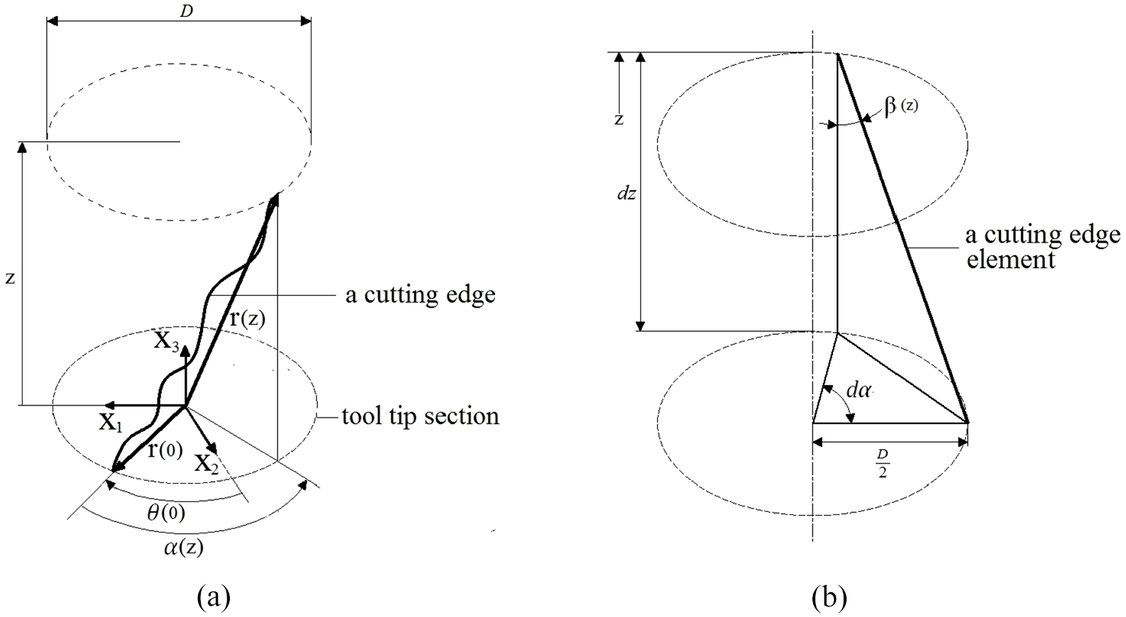
Geometric and kinematic parameters of a cutting edge: (a) a cutting edge with freely varying helix angle and (b) the angular lag of a differential cutting edge element.
The figure shows a representative cutting edge between the tool tip and a section at the axial coordinate
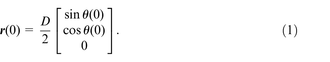
The position vector of the cutting edge element at

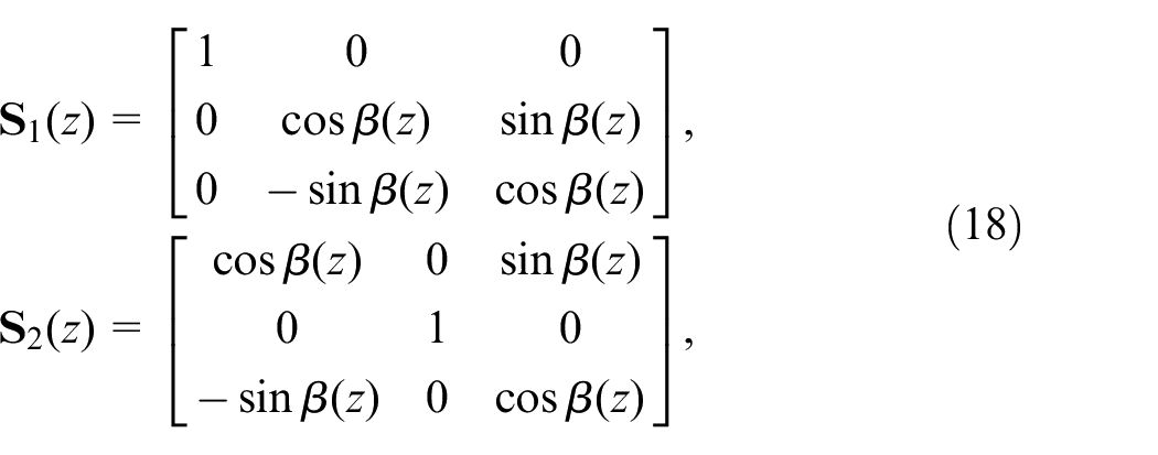
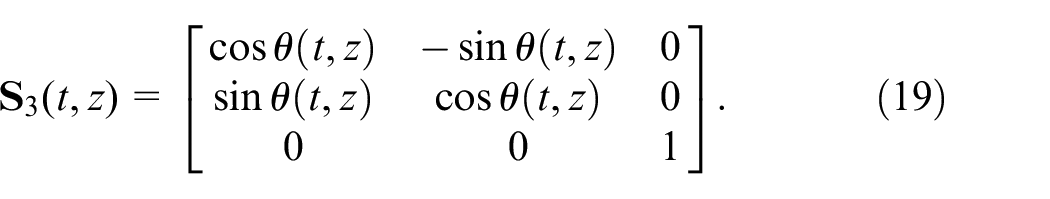
where the rotation matrix
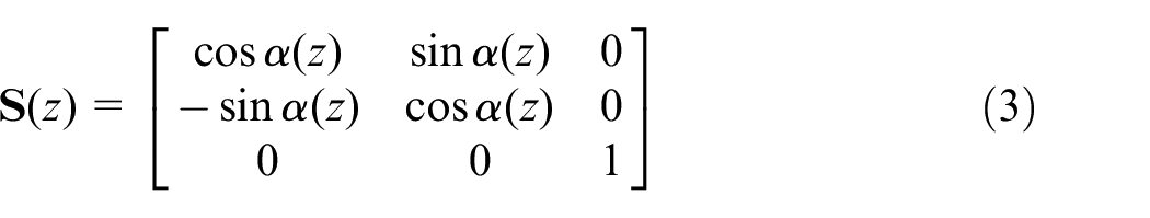
is due to the angular lag
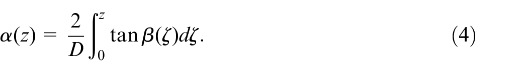
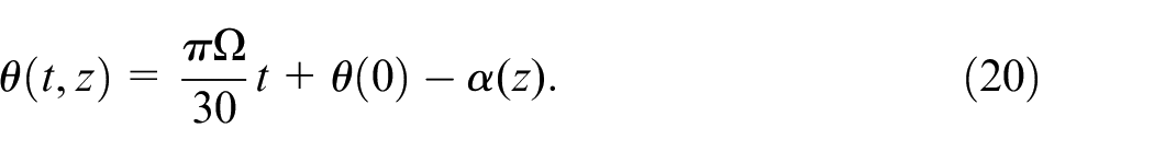
The angular lag can be computed for helix angle functions of both analytical and numerical forms using composite numerical integration schemes. The generalized composite numerical integration schemes formulated and applied for computing helix-induced functions in Ozoegwu and Eberhard
25
can be used. With
Traditionally, milling tools are manufactured with fixed helix angles meaning that the helix angles and pitch of such tools are generally given as
Tool envelope generation
The material points of cutting edges formulated in the foregoing can be adjusted using rotation and magnification operations to generate both the rake and flank surfaces which together form the envelope of a tool. The internal material points can also be generated in like manner as the envelope. To generate a tool envelope, consider that a cylindrical annulus is defined between radii

where
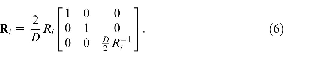
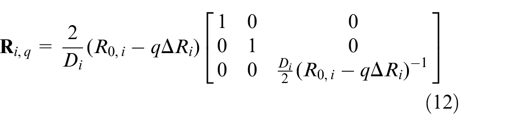
The magnification

The lag angles
where
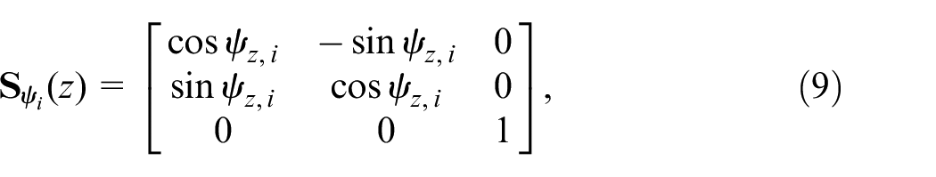
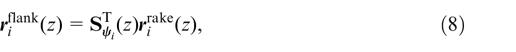
where
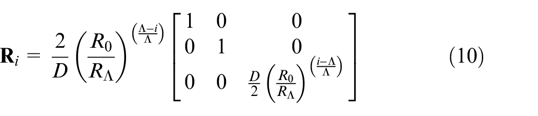
will give a geometric distribution. Spline interpolation can be used to specify the flank locations if a free-form with unknown analytical function is desired. To generate the solid model of the tool which includes the coordinates of the internal material points, each of the flank coordinates as given in equation (8) can be magnified in similar manner as suggested in equation (5) as follows

where
and
Graphical representation and geometric constraints of variable helix angle tools
Cylindrical milling tools with variable helix angles can be represented using the computed point set for the tool envelope. The problem is that a three dimensional representation will obscure some of the flutes. On the other hand, two dimensional graphs can be used to chart the important variable geometric parameters of all the flutes with equal detail. The most important variable geometric parameters for a flute are the helix angle
and the lag angle should be given as shifted angular lag (SAL) (shifted by the cumulative pitch at the tip
The geometry charts based on equations (13) and (14) will place the plots for the
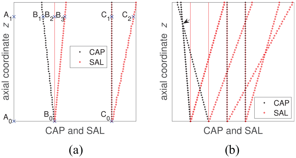
Two-dimensional representations of arbitrary tools: (a) typical two-flute tool and (b) typical four-flute tool.
The angular pitch at the axial coordinate

This inequality can only be solved analytically for
The geometric constraints described so far relates to the pitch angle due to the limit imposed by the flute depth. The pitch angle itself is dependent on the lag angle which in turn is dependent on the helix angle. The lag angle expressed in equation (4) can only have a meaningful numerical value when
Additive manufacturing of the tools
Based on the geometric description, a point set representing a tool envelope can be generated. Since the positions of the points are exactly known, the coordinates of a sample point set can be written in the format of a stereolithography (stl) file which can then be sliced in a 3D printing preprocessor for rapid prototyping of the tool represented by the point set. To generate a point set for a tool, the following steps are repeated for all the flutes:
Specify the basic geometric parameters of the tool which are the tool diameter
Specify the pitch angle at the tool tip
Compute the position
Compute the lag angle
Compute the rotation matrix
Generate the coordinate data for the rake face
Compute the pitch angle
The coordinate data of the rake and flank surfaces are combined in a structured manner to form the point set for the tool envelope.
If the number of layers of points is
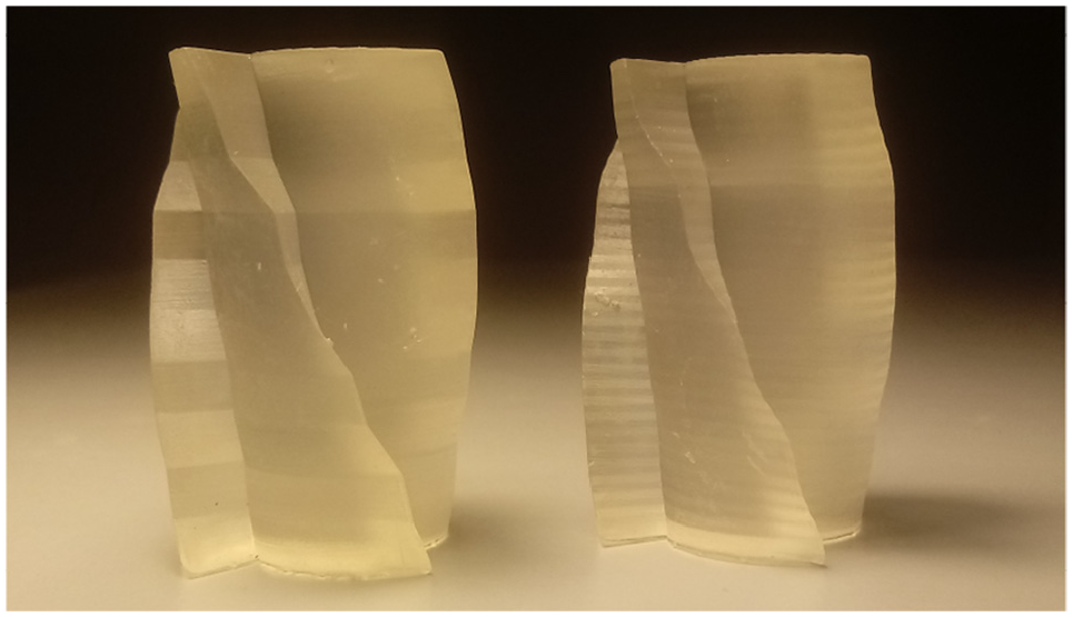
Samples of free-form helix angle tools. The left prototype has a non-smooth helix shape while the right prototype is a cubic spline smoothing of the left prototype.
Cutting force analysis
The cutting force is evaluated to provide a basis for quantified assessment of the benefits of the novel variable helix angle functions. A more beneficial variable helix angle reduces the magnitude of cutting forces and hence reduces the amplitude of cutting force-induced periodic vibrations in relative terms. Reduction of cutting power and energy which are directly proportional to cutting force is a major criterion of sustainable machining.
The popular so-called mechanistic methods to compute cutting forces are the linear and power force laws.
26
The laws are empirically established as
Every differential element of the cutting edge is subjected to differential force components from which the cutting force can be integrated, see Figure 4(a). The cutting edge element is subjected to the differential normal

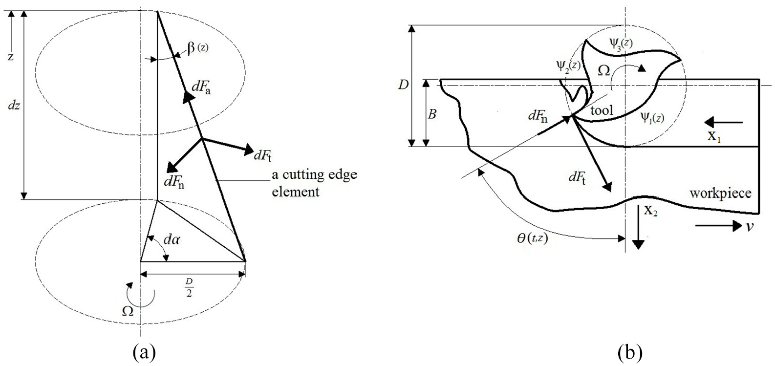
Forces and kinematic parameters of a cutting edge element: (a) spatial view and (b) planar view.
where

and
The angle
The differential cutting force vector

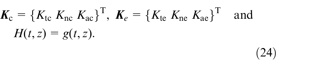
For the power force model,
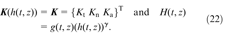
For the linear model,

where
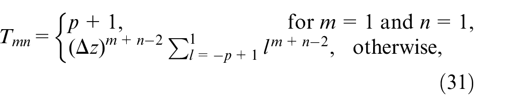
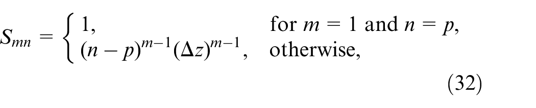
According to Ozoegwu and Eberhard,
31
the chip thickness is given as
where
where
where
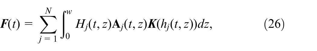
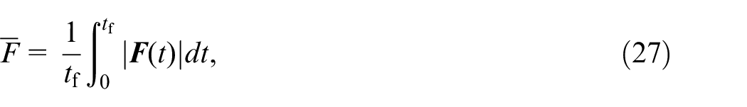
The criterion for identifying a better variable helix angle function is a better reduction of the magnitudes of cutting forces. In addition, reduction of the mean cutting force
Examples
Different variable helix angle functions
Variable helix angles
In Okafor and Sultan, 22 harmonic helix angles were interpolated using cubic splines while in Dombovari and Stepan, 5 helix angles were derived from explicitly specified harmonic lag angles. Since the helix angle is a primarily specified geometric parameter of milling tools, the harmonic helix angle is expressed explicitly here in the form
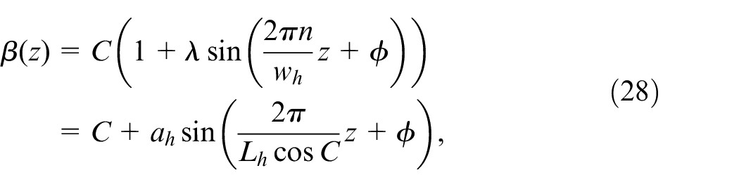
where
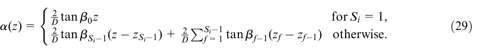
Tools with non-smooth variable helix angles can be modeled in a piece-wise manner by tagging the cutting edge segments between the depths
The smoothed free-forms rely on numerically specified non-smooth values of helix angles at discrete axial depth locations which are then smoothed with polynomial and various spline interpolations to ensure smooth variable helix angles. The simplest interpolated variable helix angle is the linear form

where

While polynomial interpolations are based on the nodal boundaries of
Numerical results and discussions
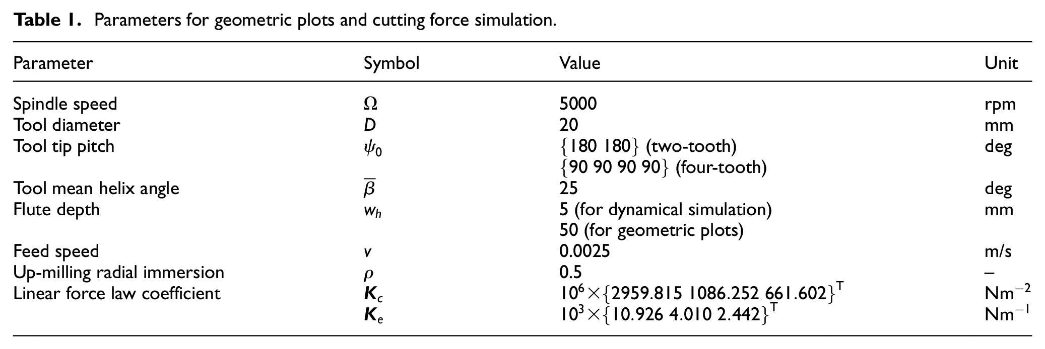
In what follows, the milling dynamics of the example variable helix angles relative to the benchmark of a conventional fixed helix angle are compared. This is judged in terms of the extent of suppression of cutting forces induced by the considered variable helix angles relative to the benchmark. The harmonic helix tools have the shape parameters
Parameters for geometric plots and cutting force simulation.
Effects of different harmonic parameters on mean cutting force
To check for the possible benefits of free-form helix angles, a comprehensive comparison involving five four-fluted tools with variable helix angle types that span all the considered cases is carried out. Since the helix angle has a strong effect on cutting forces, the benchmark tool (tool 1) and all the five compared tools are defined such as to have equal mean helix angle
Designs, properties, and cutting force reductions of the compared tools.
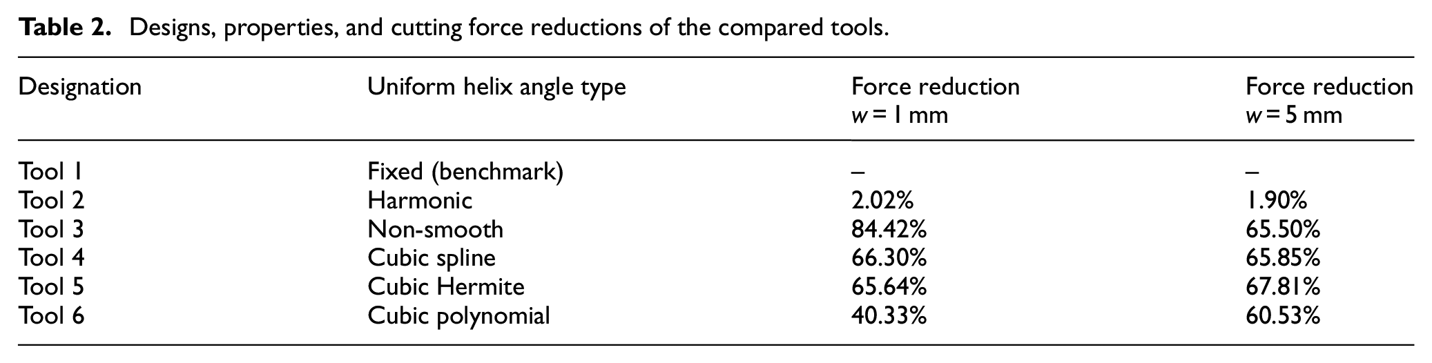
The variable helix angle parameters of tool 2 are
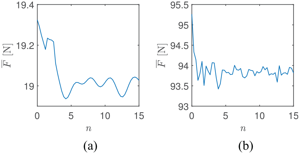
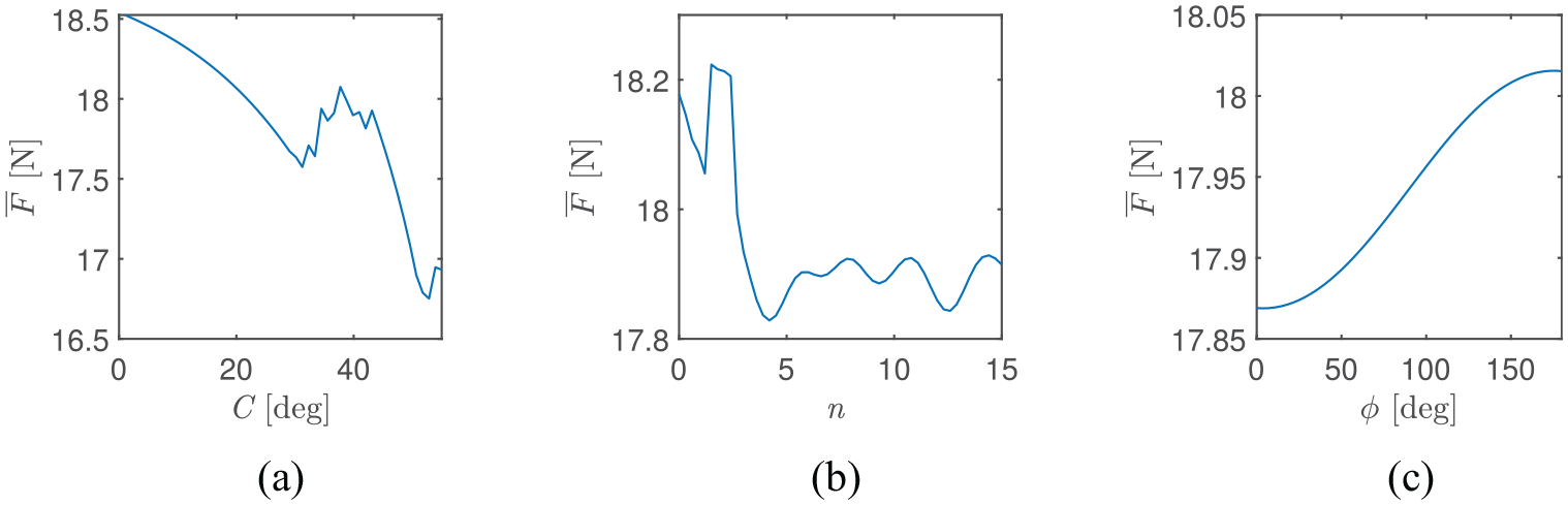
The effects of variation of number of wave cycles
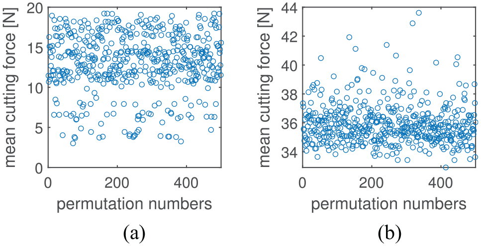
The effects of permutations of sampled helix angles along the cutting edges on the mean cutting forces
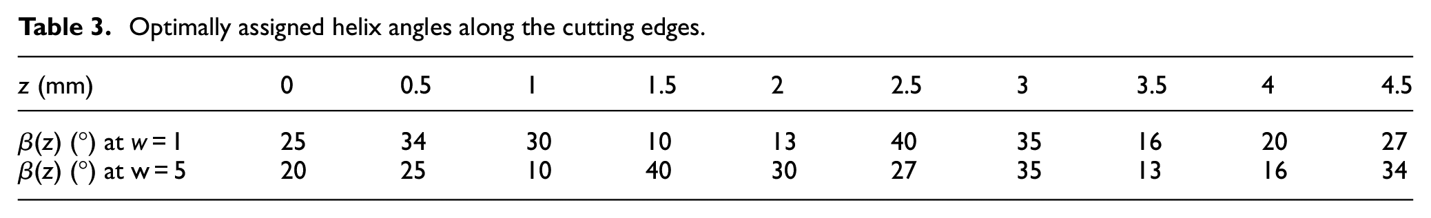
Optimally assigned helix angles along the cutting edges.
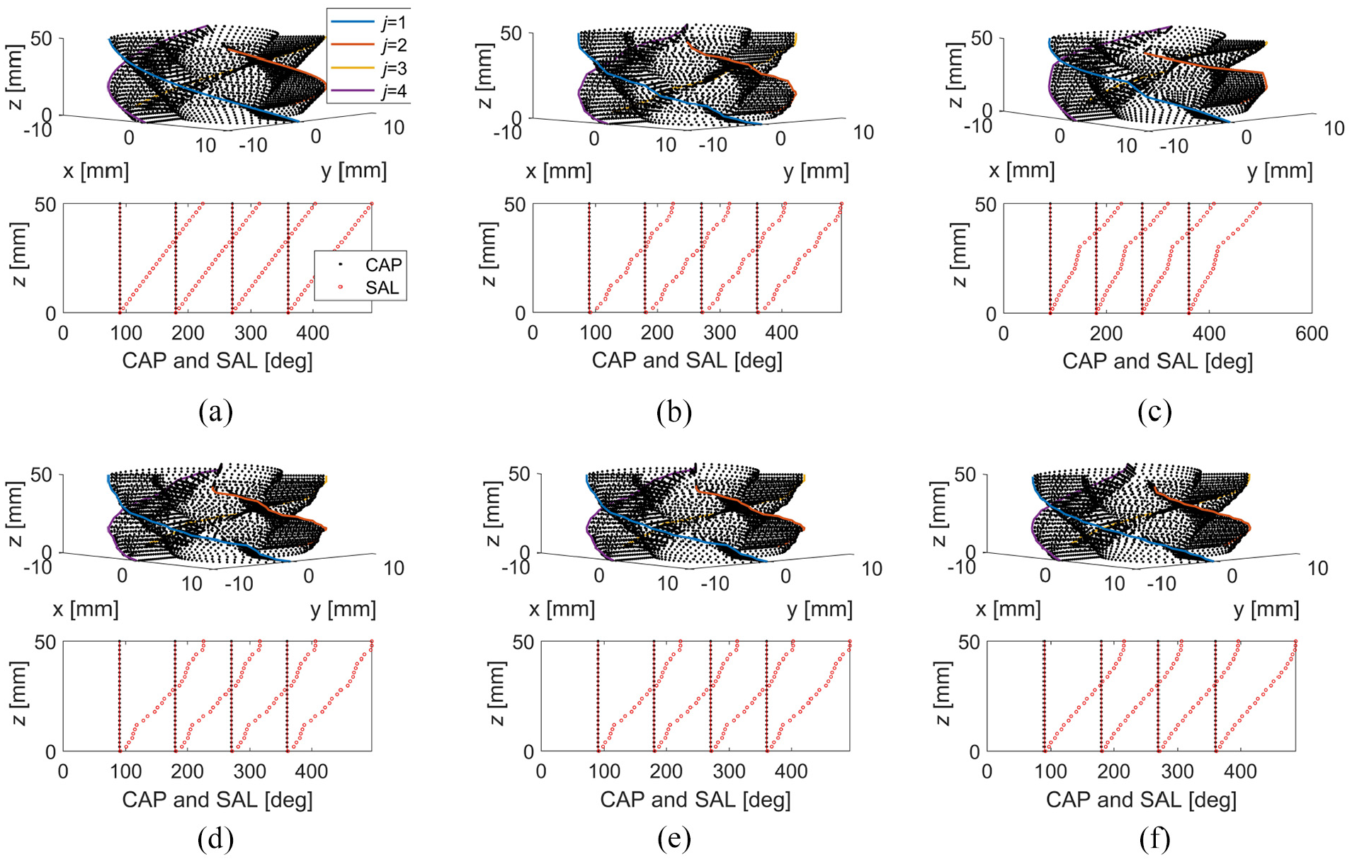
Envelope point sets and graphical representation of the compared tools: (a) tool 1, (b) tool 2, (c) tool 3, (d) tool 4,(e) tool 5, and (f) tool 6.
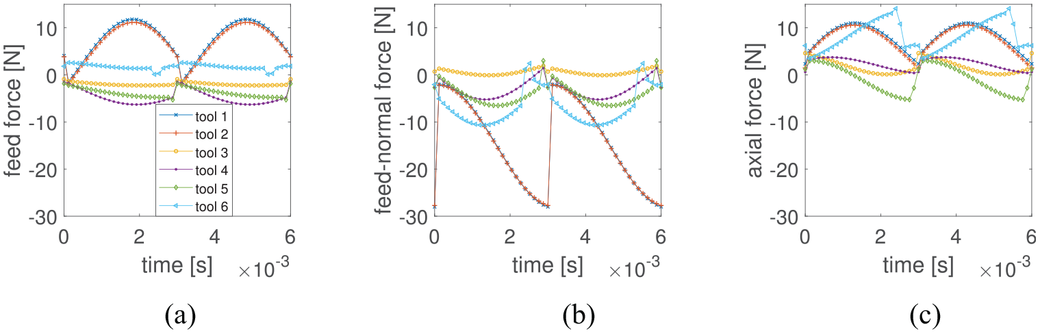
Components of the cutting forces for axial depth of cut of 1 mm: (a) feed direction, (b) feed-normal direction, and (c) axial direction.
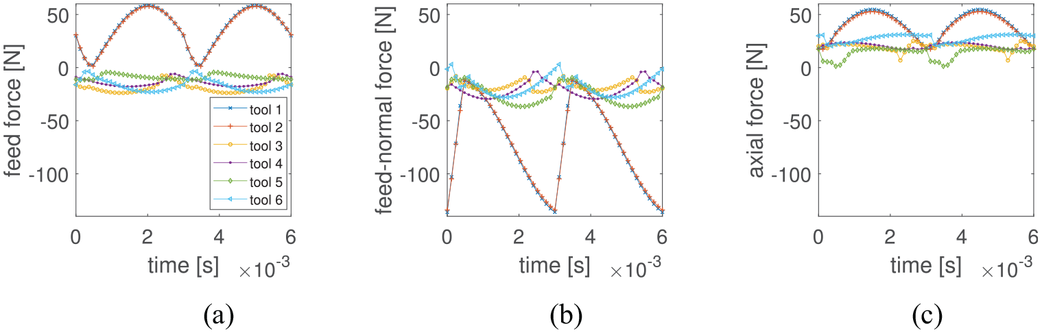
Components of the cutting forces for axial depth of cut of 5 mm: (a) feed direction, (b) feed-normal direction, and(c) axial direction.
Conclusions
Milling tools with shape variations are increasingly being deployed in production because of their favorable dynamics but their potential and possible options are not fully exploited because definition of variable helix shapes on flutes is difficult to perform systematically. Motivated by this limitation, an analytical method that simplifies the realization of generalized variable helix angles on flutes through additive manufacturing is formulated and demonstrated. The geometric features of a tool were captured to generate a point set which represents the tool envelope to be exported to 3D printers for additive manufacturing. A simplified two dimensional graphical representation for the three dimensional tools is established for variable geometries and the associated geometric constraints. The dynamics of the tools is analyzed to justify their benefits in terms of cutting force reduction. The innovative tools with non-smooth variable helix angles and smooth free-form helix angles showed significant promise for cutting force reduction. Relative to a conventional fixed helix tool of same mean helix angle, the innovative tools recorded 40.33%–84.42% force reductions at axial depth of cut of 1 mm and 60.53%–67.81% force reductions at axial depth of cut of 5 mm. Therefore, geometric design of tools can be exploited in suppressing cutting forces, and the other benefits associated with cutting force reduction like form error reduction, vibration reduction, machining energy reduction, and tool life elongation.
Footnotes
Appendix
Acknowledgements
The described research was done while the first author visited the ITM at the University of Stuttgart in 2020.
Declaration of Conflicting Interests
The author(s) declared no potential conflicts of interest with respect to the research, authorship, and/or publication of this article.
Funding
The author(s) disclosed receipt of the following financial support for the research, authorship, and/or publication of this article: This stay was funded by the Priority Program SPP 1897 “Calm, Smooth, and Smart” of the DFG (German Research Foundation). This support is highly appreciated.