
Abstract
The dynamic properties of aerostatic spindle systems vary with the spindle speed and have a significant impact on the processing quality of ultra-precision machine tools. In this article, using the ICEM CFD, the structured grid model of a large-span scale gas film is built under the condition in which the ratio of the spindle gas film length to the gas film thickness is 13,100. Integral calculation model of spindle and thrust is established and CEL expressions are compiled based on dynamic meshing technique to acquire trajectory of aerostatic spindle system. The degree of freedom method is used to obtain flow field of spindle system. Considering the spindle system as an elastomer, the influence of rotational speed on natural frequencies is studied under the flow field boundary. The results indicate that the former four-order natural frequencies of the aerostatic spindle system will clearly increase as the rotational speed increases. The increase in the fifth- to seventh-order natural frequencies is small, and the eighth-order natural frequency is almost invariable. The flow field has little influence on the mode shapes of the aerostatic spindle system. The former four-order natural frequencies of spindle system decrease considering rotation effects. Rotational speed and rotation effects mainly impact the tilting motion natural frequencies of spindle and thrust.
Keywords
Introduction
Aerostatic spindles have several advantages, such as high precision, low friction, low temperature rising, and long service life, compared to traditional spindles. 1 Additionally, because they are the core component of ultra-precision machine tools, aerostatic spindle systems have a significant impact on the quality of machining workpieces. 2 During the process of cutting a workpiece by an ultra-precision machine tool, the aerostatic spindle system generates self-excitation and forced vibration due to the rotation of the spindle and the cutting force so that it reduces the machining precision and surface quality of the workpiece. Thus, the dynamic properties of the aerostatic spindle system directly affect the performance of the ultra-precision machine tool. Because the modal analysis of aerostatic spindle system is an important part of the spindle dynamic characteristics analysis and the basis of the ultra-precision machine tools dynamics analysis, studying the modal characteristics of the aerostatic spindle is important to the structural performance analysis and dynamic design. Studies on the dynamic performance of the spindle have received significant attention in recent years. Martin et al.’s 3 results manifested that spindle vibration makes an impact on surface topographies. Lee and colleagues4,5 built up a model between the tool and workpiece to predict the surface profile using only one certain vibration frequency and amplitude. Currently, the dynamic performance analysis methods of the spindle system primarily include the finite element method, centralized parameter method, transfer matrix method and experimental modal analysis (EMA). 6 Lin et al. 7 stated that the finite element method was the most effective method because it could simulate complicated models and boundary conditions. Nelson and McVaugh 8 and Nelson 9 established the system matrix using the Timoshenko beam theory, in which the dynamic characteristics of a spindle system under the effects of rotational inertia, gyroscopic moments, shear deformation, and axial load were studied. Li and Shin10–12 established the dynamic model of a thermo-mechanical motorized spindle, which included a dynamic model of the bearing and thermal model of the spindle. The thermal model coupled with the spindle system through the thermal expansion in the bearing configuration and the thermal transmission of the system. They analyzed the thermal expansion of the bearing as well as the resulting changes in the dynamic properties. Taplak and Parlak 13 used a finite element method to implement the dynamic analysis of the spindle of a gas turbine. They obtained the critical rotational speed, Campbell value, and the response of the rotor. Bai et al. 14 generated a three-dimensional (3D) geometric model of a hydro-turbine main shaft using APDL, thus analyzing the dynamic performance of the spindle and obtaining the critical speed at the spin speed. Wang and Yau 15 combined the differential transformation method and the finite difference method to study the complex dynamic behavior of periodic, sub-harmonic, and quasi-periodic responses of high-speed spindle air-bearing system. Marsh 16 discussed the effects of spindle dynamics on topographies of flat surfaces in precision fly cutting. An et al. 1 experimentally and theoretically studied how the tilting motions of the aerostatic bearing spindle influences the topographies of machined surfaces in ultra-precision fly cutting. Zaghbani I 17 and Zhou et al. 18 determined that the high spin speed of the main shaft was one of the principal factors that affected the dynamic properties of the machine tool. Many factors affect the dynamic characteristics of the spindle system, such as cutting condition, tool tip geometry, spindle speed, depth of cut and rate,4,5,19 the relative vibration between tool and workpiece,20,21 and tool tip vibration.22–24
Obviously, many researches have been made on the dynamic characteristics of aerostatic spindle system; however, there are few studies about the influence of rotational speed on the vibration frequency of the spindle system. The model does not consider the influence of the aerostatic spindle system flow field on the spindle system mode. In addition, the integral model of spindle and thrust is not considered in the calculation model. Moreover, the deformation of the spindle system is not taken into account either.
In this article, ICEM CFD is developed to establish a structured grid model, in which the large-span scale spindle and thrust integrate calculation model with the ratio of the gas film length to the gas film thickness is 13,100. In order to get the trajectory of aerostatic spindle and the flow field of the spindle system under different speeds, the fluid dynamics N-S equation and 6-degree-of-freedom (DOF) rigid body motion equations are coupled, and the CEL expressions are compiled to get the trajectory of the spindle. Considering the spindle system as an elastomer, the influence of rotational speed, rotation effects, and flow field on the natural frequencies and modes of the aerostatic spindle system is studied.
Numerical calculation
In order to acquire the trajectory of spindle, the stiffness of spindle and thrust gas film, and the flow field of the aerostatic spindle system, the fluid dynamics N-S equation of integral form and 6DOF rigid body motion equations are coupled. Section “Governing equation” is governing equation of flow field calculation and section “Calculation for trajectory of spindle” represents 6DOF rigid body motion equations.
Governing equation
The motion of gas is governed by N-S equation, which can be expressed by the conservation laws of mass, momentum, and energy. Because the CFX 18.0 software is based on the FVM, the governing equation can be written as follows

where

The contravariant velocity V normal to the surface element dS is defined as follows

Here
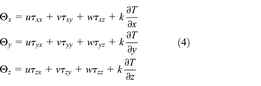
where
Calculation for trajectory of spindle
The equations describe the rigid body motion in the coordinate system


where m is the mass of the spindle and thrust,
The rotational equation of motion about center of mass are described as follows


where
Modal analysis
The dynamic equation in the multi-degree-of-freedom structure system can be expressed in equation (9) as follows

where
Based on the structural dynamic theory, the natural frequencies of the structure system are determined by the characteristics of the structure. Therefore, the dynamic equation of the structure can be simplified in equation (10) as follows

If it is assumed that the structure follows simple harmonic motion, then the solution of equation (11) can be given as follows

where
By substituting equation (11) into equation (10), equation (12) can be obtained as follows

Since equation (12) holds true at any time (t), it can be simplified as follows

When machining the workpiece, the spindle of the ultra-precision machine tool rotates. The stiffness of the spindle system reduces due to its rotation effects. Furthermore, the dynamic equation in this case can be expressed in equation (14) as follows

where
Dynamic meshing calculation model of the aerostatic spindle system
Geometric model
This study considers a certain ultra-precision single-point diamond fly cutting machine as the object of study. The aerostatic spindle rotational precision is higher than 0.05 μm. Subtle structures, such as chamferings and tapped holes, are ignored during the modeling process. Additionally, the solid domain, fluid domain, and boundary conditions related to the study are reserved. The simplified structure is illustrated in Figure 1, and the structure of the spindle system is symmetrical about the axis line.

Structural diagram of the spindle system.
The material and structural parameters of the aerostatic spindle are provided in Tables 1 and 2, respectively.
Material parameters of the aerostatic spindle system.

Structural parameters of the aerostatic spindle system.

Establishing a finite element model for the large-span scale aerostatic spindle system
The proper establishment and high quality of grids are a prerequisite to ensure the accuracy of the CFD calculation.
25
In this study, because the length of the spindle gas film in the computational model is 13,100 times the thickness of the spindle gas film, it is extremely easy to generate negative grids during the meshing and calculating process. Therefore, it is necessary to establish a high-quality mesh model. A multi-block is used to generate the topology structure of the flow field in the ICEM CFD, thus achieving the mesh of a large-span scale structured grid model. This model can efficiently improve the computation efficiency by meshing hexahedral grids because the number of grids is reduced. To better simulate boundary layer flow,

Grids of the fluid domain.

Grids of the inlet flow field.

Grids of the spindle.
Dynamic meshing calculating model of the aerostatic spindle system
The computational parameters of dynamic meshing technique are listed in Table 3.
Computational parameters of dynamic meshing technique.

When the aerostatic spindle system rotational speed is n = 0 r/min, the pressure contour of the spindle and thrust gas film can be illustrated in Figure 5. Moreover, Figure 6 depicts the coupling model of loading flow field onto the spindle and thrust surfaces.

Pressure contour of the gas film.

Coupling model of the aerostatic spindle.
The fluid domain distribution of spindle and thrust is shown in Figure 5, and the pressure distribution has periodic variation characteristics. The pressure near inlet orifices is relatively high. The pressure keeps relatively steady between inlet orifices in the axial direction and the pressure in the air cavity is about the atmospheric pressure. Upper thrust film and lower thrust film nearly have similar pressure distribution which the pressure near the orifice is relatively high and the pressure decreases to the outlet of gas film gradually. Loading the flow field onto the surface of spindle and thrust can be used to analyze the static mechanical structure and renew the mass and stiffness distribution of the spindle system, thus obtaining the natural frequencies and the corresponding modes.
Modal analysis process
This study performs a modal analysis of the spindle system based on the dynamic meshing technique. During the analysis process, the influences of the spindle rotational speed, rotation effects, and flow field on the natural frequencies of the spindle system are considered. The detailed analysis process is depicted in Figure 7.
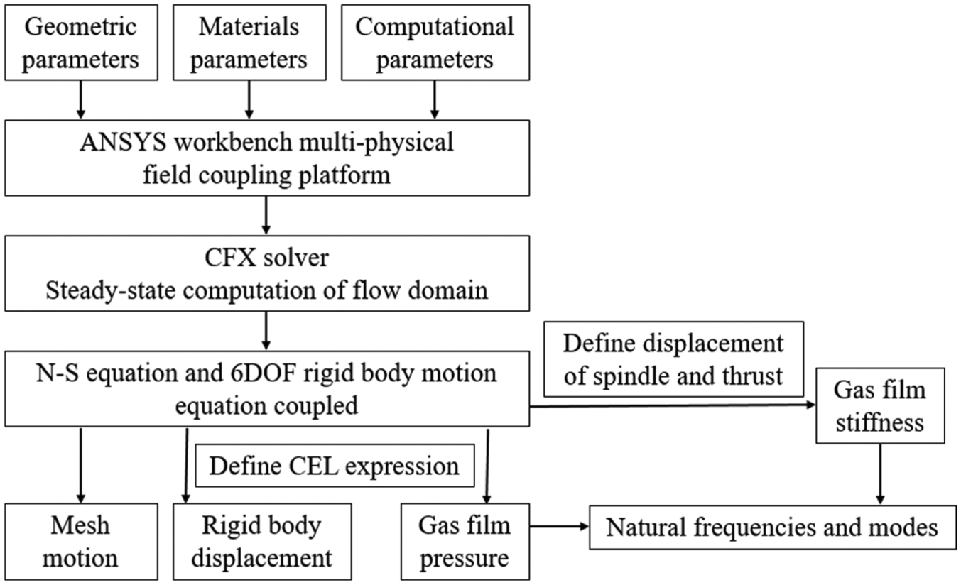
Modal analysis process.
As the spindle rotates to produce inertia force, the structure of the spindle system is deformed and stress concentrations appear; therefore, the mass and stiffness matrices of the spindle structure are changed, hence affecting the natural frequencies of the spindle system. Concurrently, the distribution of the flow field pressure may change at different rotational speeds, which leads to variations in the natural frequencies of the spindle system. Thus, it is practical to consider the rotation effects and the distribution of the flow field at different rotational speeds when performing the modal analysis of the spindle system.
Validation of the computational model
To confirm the computation method and model, a 6DOF calculation and modal analysis of the example in Yu et al. 26 are performed.
The geometric parameters of the hydrostatic bearing oil film in Yu et al. 26 are shown in Table 4.
Geometric parameters of oil film.

Establishing the oil film finite element model at an eccentricity e = 0.5 of Yu et al., 26 the topology structure of oil film is split using ICEM CFD. Through the grid sensitivity analysis, the number of grids is determined to be 2.4E6, the geometric model and grid model of the oil film are as shown in Figure 8.

Oil film model: (a) geometric model, (b) structure of orifice, (c) mesh of oil film, and (d) grids near the orifice.
The pressure distribution of oil film is analyzed and presented in Figure 9. The maximum pressure of the oil film is about 7 MPa, locating supply passages and near the bottom of orifices. The pressure keeps steady inside the oil cavity, and then it decreases from the edge of oil cavity to the outlet of oil film gradually. It can be found that the pressure distribution rule of the oil film is primarily consistent with Yu et al. 26

Pressure distribution of oil film: (a) pressure contour of the oil film and (b) pressure contour near the orifice.
Experimental process in Yu et al. 26 is described as follows. Under the condition of static pressure supply (oil supply pressure ps = 7 MPa), spindle is knocked by hammer and the transient impulse excitation is applied to the spindle system so that the vibration of spindle system is generated. Vibration signal is collected through the acceleration sensor, and then the frequency spectrum is analyzed by the dynamic signal instrument. Finally, the experiment results of spindle system natural frequencies are acquired and is shown in Table 5.
Comparison of the natural frequencies of the spindle system.
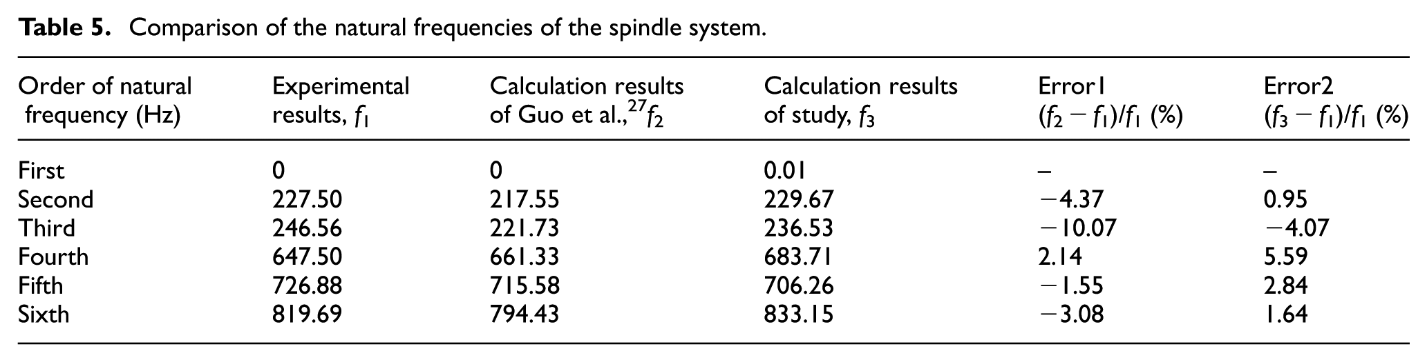
When the oil supply pressure is Ps = 7 MPa and the rotational speed is n = 0 r/min, the block Lanczos method is used to solve the modal solution of the spindle system. Furthermore, the natural frequencies of the spindle system can be compared with the calculation results in Yu et al., 26 as indicated in Table 5.
The former six-order natural frequencies of the spindle system, which are calculated in this study, are compared with the experimental results. It can be seen from Table 5 that the maximum error is 5.59%, while the minimum error is 0.95%; the error is rather small; therefore, by using the modeling method of this article, the spindle system modal analysis considering the flow field as boundary can obtain a relatively higher calculation accuracy.
Analysis of the grid sensitivity
Grid density has a certain influence on the computational accuracy of the CFD. Grids that are too dense will increase the solution time, whereas grids that are too sparse may result in less accuracy or non-convergence of the solution. Therefore, to balance the calculation accuracy and time cost, the grid sensitivity analysis is necessary. When the rotational speed is n = 1000 r/min and the gas supply pressure is Ps = 0.4 MPa, the changes in the natural frequencies of the spindle system with the gas film meshed into 478,100, 539,980, 601,860, and 663,740 elements and the spindle meshed into 14,870, 19,788, and 21,987 elements are studied, as indicated in Figure 10. As can be seen in Figure 10, the influence of the changes in the number of gas film grids and spindle grids on the natural frequencies of the spindle system is less than 0.5 Hz. Thus, for the spindle system’s modal analysis, the number of gas film grids and spindle grids is selected to be 601,860 and 19,788, respectively.

Influence of the number of grids on the natural frequency of the spindle system.
The dynamic behaviors of spindle system
As shown in Figure 1, the spindle system consists of spindle and thrust. In the actual rotation movement, the accuracy of radial and axial motion of spindle system determines the machining accuracy of ultra-precision machine tools. This article has studied the trajectory of spindle system at different speeds.
Compiling CEL expression in CFX, the radial and axial displacement responses of the spindle system are achieved. When the spindle system rotates at 0, 2000, and 5000 r/min, the displacement of x, y and z direction of spindle system is shown in Figure 11.

The displacement of x, y and z direction of spindle system at different rotational speeds.
From Figure 11, the displacements in x and y direction of the spindle system are very small, and the maximum value is no more than 20 nm. When the spindle system is in working state, the radial and axial displacement continue to vibrate with the iteration time. After a period of time, it tends to be stable.
As shown in Table 6 is the thickness of upper and lower thrust gas film at different rotational speeds. The corresponding change curve is plotted in Figure 12.
The thickness of upper and lower thrust gas film at different rotational speeds.
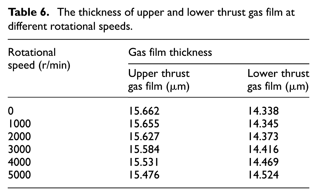

The change trend of the thickness of upper and lower thrust gas film at different rotational speeds.
The total weight of the spindle system should be balanced with the pressure difference between upper and lower gas film. It is known from Table 6 and Figure 12 that with the increase in the rotational speed, the thickness of upper thrust film decreases, and the thickness of lower thrust gas film increases. With the rotational speed increasing, the stiffness of thrust gas film becomes larger, consequently, the displacement of thrust is reduced.
Modal analysis of spindle system considering flow field boundary
Establishing the mechanical model
The spindle fluid domain keeps the stability of the spindle in horizontal direction. The main function of the thrust fluid domain is to support the spindle and thrust and keeps the stability of the spindle and thrust in the axial direction. So the simplifications performed in the modal analysis of the spindle system can be summarized as follows:
The spindle fluid field only has radial stiffness and the thrust fluid field only has axial stiffness, hence ignoring the influence of the cross stiffness.
The fluid domain is simplified as an elastic support and averagely distributed between the spindle and the bearing, as depicted in Figure 13.

Equivalent spring model.
The support stiffness of a bearing refers to the axis of the spindle offsetting a micro distance, and the ratio of increment of the load carrying capacity of gas film to the micro distance can be given in equation (15) as follows

where kxx is the radial stiffness of the x orientation, kyy is the radial stiffness of the y orientation, kzz is the axial stiffness of the z orientation, Fx is the bearing capacity of the gas film in the x orientation, Fy is the bearing capacity of the gas film in the y orientation, Fz is the bearing capacity of the gas film in the z orientation, and Δx, Δy, and Δz are the displacement in each respective orientation.
When calculating the stiffness of the gas film, the change in the bearing capacity of the x, y, and z orientations is solved by the given micro displacement in the x, y, and z orientations. According to Guo et al., 27 the accuracy of calculating the stiffness is higher when the micro displacements, Δx/h0, Δy/h0, and Δz/h0 are typically between 0.005 and 0.010.
Because the object of study bearing force is small in this study, the changes in the gas film stiffness are studied, for which the spindle is located at its center. Using the dynamic mesh technique, the given micro displacement in the x, y and z orientation is 0.1 μm. Then Δx/h0 = Δy/h0 = Δz/h0 = 0.010 and a higher accuracy of the gas film stiffness can be obtained. Furthermore, the gas film bearing capacity of the x, y and z orientations can be calculated using CFX post-processing, and the stiffness of the gas film is achieved. Table 7 presents the gas film stiffness of the unit area of spindle at different rotational speeds when the inlet pressure is Ps = 0.4 MPa and the spindle eccentricity is e = 0.
Gas film stiffness of the unit area at different rotational speeds.

No rotation effects
When the rotational speed is n = 1000 r/min, the former eight vibration modes without considering the rotation effects and considering flow field boundary are shown in Figure 14.
Former eight vibration modes of the spindle system.
From Figure 14, the former eight vibration modes and the corresponding deformation modes of the spindle system can be obtained without considering the rotation effects and considering the flow field boundary. The first- and second-order vibration modes are the tilting of the thrust. The maximum tilting mode deformation locates the bottom of lower thrust, and the minimum tilting mode deformation locates the head of spindle. The third- and fourth-order vibration modes are the tilting of the head of spindle. The maximum tilting mode deformation locates the head of spindle, and the minimum tilting mode deformation locates the bottom of lower thrust. The fifth-order vibration mode is the up and down movement of spindle and thrust. The maximum movement mode deformation locates the head of spindle, and the minimum tilting mode deformation locates the edge of thrust. The sixth- and seventh-order vibration modes are the bending deformation of spindle. The maximum bending mode deformation locates the edge of thrust, and the minimum bending mode deformation locates the middle part of spindle. And finally the eighth-order vibration mode is the expansion deformation of spindle. The maximum expansion mode deformation locates the head of spindle, and the minimum expansion mode deformation locates the bottom of thrust.
The natural frequencies of the spindle system without considering the rotation effects and considering the flow field boundary are depicted in Table 8 and Figure 15.
The frequencies of the spindle system without considering the rotation effects and considering the flow field boundary.


The frequencies of the spindle system without considering the rotation effects and considering flow field boundary.
Table 8 and Figure 15 demonstrate that the natural frequencies of the spindle system of the first and second orders, third and fourth orders, and sixth and seventh orders are extremely close to each other, and the vibration modes are orthogonal; thus, they can be regarded as double roots. When the flow field is considered but no rotation effects, except eighth-order natural frequency, others increase generally with the increase in the rotational speed because the equivalent stiffness rises with the increase in the rotational speed. Furthermore, the extent of the changes in the natural frequency of the first, second, third, and fourth order are the most apparent, and the differences of natural frequencies between the rotational speed n = 5000 r/min and n = 0 r/min are 301.19, 301.22, 406.78, and 406.67 Hz, respectively. The higher order natural frequencies change only slightly with the increase in the rotational speed. The fifth-, sixth-, and seventh-order natural frequencies are affected by the rotational speed, and the value of increasing are 55.2, 61.2, and 61.2 Hz, respectively. When the rotational speed is raised from 0 to 1000 r/min and 3000 to 4000 r/min, the former four-order natural frequencies rise obviously. When the rotational speed is raised from 4000 to 5000 r/min, the increase in the fifth- to seventh-order natural frequencies is relatively high. The eighth-order natural frequency does not change with the increase in the rotational speed. Thus, it can be seen that when the rotation effects are not considered and considering the flow field boundary, the spindle system rotational speed has a considerable influence on the natural frequencies corresponding to the tilting modes of the spindle and thrust.
Rotation effects
When the spindle speed is n = 1000 r/min, the former eight vibration modes considering the rotation effects and flow field boundary can be obtained, as indicated in Figure 16.

Former eight vibration modes of the spindle system.
From Figure 16, the former eight vibration modes and the corresponding deformation modes of the spindle system can be obtained considering the rotation effects and flow field boundary. The first- and second-order vibration modes are the tilting of the thrust. The maximum tilting mode deformation locates the bottom of lower thrust, and the minimum tilting mode deformation locates the head of spindle. The third- and fourth-order vibration modes are the tilting of the head of spindle. The maximum tilting mode deformation locates the head of spindle, and the minimum tilting mode deformation locates the bottom of lower thrust. The fifth-order vibration mode is the up and down movement of spindle and thrust. The maximum movement mode deformation locates the head of spindle, and the minimum tilting mode deformation locates the edge of thrust. The sixth- and seventh-order vibration modes are the bending deformation of spindle. The maximum bending mode deformation locates the edge of thrust, and the minimum bending mode deformation locates the middle part of spindle. And finally, the eighth-order vibration mode is the expansion deformation of spindle. The maximum expansion mode deformation locates the head of spindle, and the minimum expansion mode deformation locates the bottom of thrust. From the above analysis and comparing with the condition of without the considering rotation effects and considering the flow field boundary, the rotation effects have little effect on maximum mode deformation of spindle system and the minimum mode deformation increases generally.
The natural frequencies of the spindle system considering the rotation effects and flow field boundary are provided in Table 9 and Figure 17.
The frequencies of the spindle system considering the rotation effects and flow field boundary.


The frequencies of the spindle system considering the rotation effects and flow field boundary.
Table 9 and Figure 17 indicate that the natural frequencies of the spindle system of the first and second orders, third and fourth orders, and sixth and seventh orders are extremely close to each other, and the vibration modes are orthogonal, so they can be regarded as double roots. When the rotation effects and flow field boundary are considered, except eighth-order natural frequency, others increase generally with the increase in the rotational speed because the equivalent stiffness rises with the increase in the rotational speed. Furthermore, the degrees of variations in the natural frequency of the first, second, third, and fourth order are relatively obvious, and the differences of natural frequencies between the rotational speed n = 5000 r/min and n = 0 r/min are 295.41, 295.44, 404.58, and 404.47 Hz, respectively. However, the fifth- to eighth-order natural frequencies change with a small amplitude when the rotational speed increases. The fifth-, sixth-, and seventh-order natural frequencies are affected by the rotational speed with the value of increasing are 55.2, 61.6, and 61.6 Hz, respectively. When the rotational speed is raised from 0 to 1000 r/min and 3000 to 4000 r/min, the former four-order natural frequencies rise obviously. When the rotational speed is raised from 4000 to 5000 r/min, the increase in the fifth- to seventh-order natural frequencies is relatively high. The eighth-order natural frequency does not change almost with the increase in the rotational speed. When the rotational speed n = 4000 and 5000 r/min, the decreasing values of eighth-order natural frequencies are 0.1 Hz. Thus, it can be seen that when the rotation effects and flow field boundary are considered, the spindle system rotational speed has a considerable influence on the natural frequencies corresponding to the tilting modes of the spindle and thrust.
Modal analysis of the spindle system without considering the flow field boundary
Establishing the mechanical model
The mechanical model of the modal analysis for the spindle system based on fluid coupling is depicted in section “Dynamic meshing calculating model of the aerostatic spindle system.”
No rotation effects
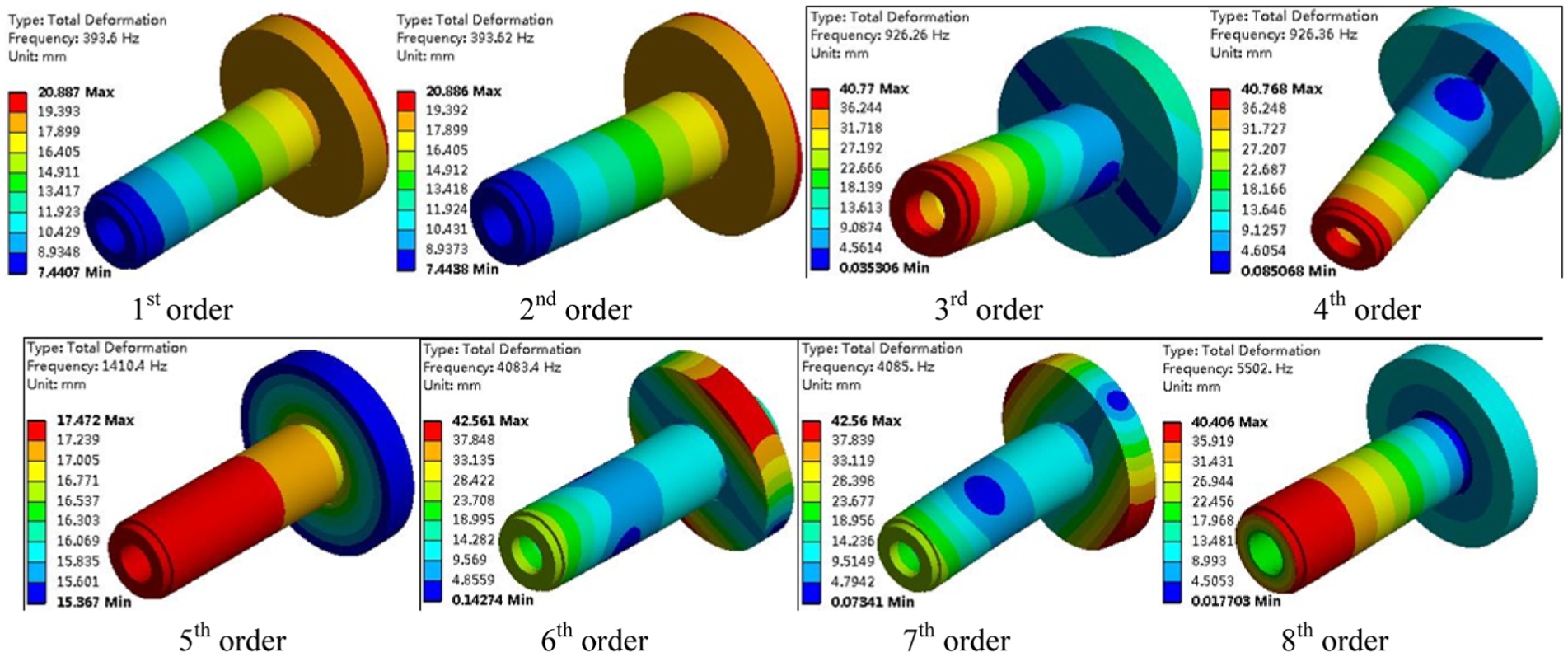
Figure 18 illustrates the former eight order vibration modes of the spindle system without considering the rotation effects and flow field boundary when the spindle system rotational speed is n = 1000 r/min.

Former eight vibration modes of the spindle system.
From Figure 18, the former eight vibration modes and the corresponding deformation modes of the spindle system can be obtained without considering the rotation effects and the flow field boundary. The first- and second-order vibration modes are the tilting of the thrust. The maximum tilting mode deformation locates the bottom of lower thrust, and the minimum tilting mode deformation locates the head of spindle. The third- and fourth-order vibration modes are the tilting of the head of spindle. The maximum tilting mode deformation locates the head of spindle, and the minimum tilting mode deformation locates the bottom of lower thrust. The fifth-order vibration mode is the up and down movements of spindle and thrust. The maximum movement mode deformation locates the head of spindle, and the minimum tilting mode deformation locates the edge of thrust. The sixth- and seventh-order vibration modes are the bending deformation of spindle. The maximum bending mode deformation locates the edge of thrust, and the minimum bending mode deformation locates the middle part of spindle. And finally the eighth-order vibration mode is the expansion deformation of spindle. The maximum expansion mode deformation locates the head of spindle, and the minimum expansion mode deformation locates the bottom of thrust. Comparing with the condition of without the considering rotation effects and considering the flow field boundary, the low order maximum mode deformation increases and high-order maximum mode deformation keeps steady and the minimum mode deformation decreases generally under the influence of flow field.
The natural frequencies of the spindle system without considering the rotation effects and flow field boundary are illustrated in Table 10 and Figure 19.
The frequencies of the spindle system without considering the rotation effects and flow field boundary.
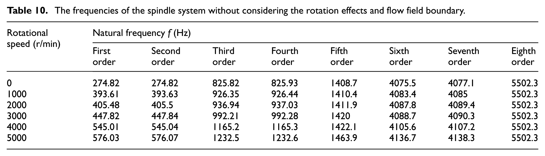

The frequencies of the spindle system without considering the rotation effects and flow field boundary.
Table 10 and Figure 19 demonstrate that the natural frequencies of the spindle system of the first and second orders, third and fourth orders, and sixth and seventh orders are extremely close to each other, and the vibration modes are orthogonal; thus, they can be regarded as double roots. When the rotation effects and flow field boundary are not considered, except eighth-order natural frequency, others increase generally with the increase in the rotational speed because the equivalent stiffness rises with the increase in the rotational speed. Furthermore, the extent of the changes in the natural frequency of the first, second, third, and fourth orders are the most apparent, and the differences of natural frequencies between the rotational speed n = 5000 and 0 r/min are 301.21, 301.25, 406.68, and 406.67 Hz, respectively. The higher order natural frequencies change only slightly with the increase in the rotational speed. The fifth-, sixth-, and seventh-order natural frequencies are affected by the rotational speed, and the value of increasing are 55.2, 61.2, and 61.2 Hz, respectively. When the rotational speed is raised from 0 to 1000 r/min and 3000 to 4000 r/min, the former four-order natural frequencies rise obviously. When the rotational speed is raised from 4000 to 5000 r/min, the increase in the fifth- to seventh-order natural frequencies is relatively high. The eighth-order natural frequency does not change with the increase in the rotational speed. Thus, it can be seen that when the rotation effects and flow field boundary are not considered, the spindle system rotational speed has a considerable influence on the natural frequencies corresponding to the tilting modes of the spindle and thrust.
Rotation effects
When the rotational speed is n = 1000 r/min, the former eight vibration modes considering the rotation effects and without considering flow field boundary can be obtained, as depicted in Figure 20.

Former eight vibration modes of the spindle system.
From Figure 20, the former eight vibration modes and the corresponding deformation modes of the spindle system can be obtained without considering the rotation effects and the flow field boundary. The first- and second-order vibration modes are the tilting of the thrust. The maximum tilting mode deformation locates the bottom of lower thrust, and the minimum tilting mode deformation locates the head of spindle. The third- and fourth-order vibration modes are the tilting of the head of spindle. The maximum tilting mode deformation locates the head of spindle, and the minimum tilting mode deformation locates the bottom of lower thrust. The fifth-order vibration mode is the up and down movements of spindle and thrust. The maximum movement mode deformation locates the head of spindle, and the minimum tilting mode deformation locates the edge of thrust. The sixth- and seventh-order vibration modes are the bending deformation of spindle. The maximum bending mode deformation locates the edge of thrust, and the minimum bending mode deformation locates the middle part of spindle. And finally, the eighth-order vibration mode is the expansion deformation of spindle. The maximum expansion mode deformation locates the head of spindle, and the minimum expansion mode deformation locates the bottom of thrust. From the above analysis and comparing with the condition of without the considering rotation effects and the flow field boundary, the rotation effects have little effect on maximum mode deformation of spindle system and the minimum mode deformation increases generally.
The natural frequencies of the spindle system considering the rotation effects under the fluid-solid-interaction condition are depicted in Table 11 and Figure 21.
The natural frequencies of the spindle system considering the rotation effects and without considering flow field boundary.


The natural frequencies of the spindle system considering the rotation effects and without considering flow field boundary.
Table 11 and Figure 21 demonstrate that the natural frequencies of the spindle system of the first and second orders, third and fourth orders, and sixth and seventh order are extremely close to each other, and the vibration modes are orthogonal, so they can be regarded as double roots. When the rotation effects are considered and without considering flow field boundary, except eighth-order natural frequency, others increase generally with the increase in the rotational speed because the equivalent stiffness rises with the increase in the rotational speed. Furthermore, the degrees of variations in the natural frequency of the first, second, third and fourth orders are relatively obvious, and the differences of natural frequencies between the rotational speed n = 5000 and 0 r/min are 295.43, 295.47, 404.48, and 404.47Hz, respectively. However, the fifth- to eighth-order natural frequencies change with a small amplitude when the rotational speed increases. The fifth-, sixth-, and seventh-order natural frequencies are affected by the rotational speed, and the values of increasing are 55.2, 61.6, and 61.6 Hz, respectively. When the rotational speed is raised from 0 to 1000 r/min and 3000 to 4000 r/min, the former four-order natural frequencies rise obviously. When the rotational speed is raised from 4000 to 5000 r/min, the increase in the fifth- to seventh-order natural frequencies is relatively high. The eighth-order natural frequency does not change with the increase in the rotational speed. Thus, it can be seen that when the rotation effects are considered and without considering flow field boundary, the spindle system rotational speed has a considerable influence on the natural frequencies corresponding to the tilting modes of the spindle and thrust. However, the rotational speed has no influence on frequencies corresponding to the expansion deformation of spindle.
Comparison and analysis of the natural frequency of the spindle system under different conditions
To describe the changes in the natural frequencies of the spindle system under different working conditions more clearly, the natural frequencies of each rotational speed and different working conditions are listed in Tables 12–17 for comparison and analysis.
Changes in the natural frequencies of the spindle system at the rotational speed n = 0 r/min.

Changes in the natural frequencies of the spindle system at the rotational speed n = 1000 r/min.

Changes in the natural frequencies of the spindle system at the rotational speed n = 2000 r/min.

Changes in the natural frequencies of the spindle system at the rotational speed n = 3000 r/min.

Changes in the natural frequencies of the spindle system at the rotational speed n = 4000 r/min.

Changes in the natural frequency of the spindle system at a spindle rotational speed n = 5000 r/min.

It can be seen from Tables 12 to 17 when the spindle rotational speed rises, the first- to seventh-order natural frequencies increase generally, but the eighth-order natural frequency always keeps steady. When the rotation effects are considered, the natural frequencies of the spindle system generally decrease. This result occurs because the rotation effects caused by the centrifugal force leads to a decreasing stiffness of the spindle system. As the spindle rotational speed increases, the rotation effects impact the spindle natural frequencies spindle obviously. When the rotational speed is n = 1000 r/min, the greatest reduction of first- and second-order frequency is 0.09% (0.35 Hz) after considering the rotation effects. Furthermore, when the rotational speed is n = 5000 r/min, the greatest reduction of first- and second-order frequency reaches 1.00% (5.78 Hz) under the influence of rotation effects. The rotation effects have limited effects on the fifth-, sixth-, seventh-, and eighth-order natural frequencies, and the maximum value change is 0.01% (0.4 Hz). By considering the flow field distribution, the largest change in the natural frequencies of the spindle system is no more than 0.4 Hz.
It can be demonstrated that rotation effects mainly affects former four-order natural frequencies of spindle system. That is changing the tilting vibration frequencies of spindle and thrust. In addition, pressure field has limited effects on the intrinsic characteristics of the spindle system; therefore, it is not the primary factor affecting the natural frequency in the spindle system.
Conclusion
In this study, the integral calculation model is established of spindle and thrust and compiles CEL expression based on dynamic meshing technique to acquire the flow field and trajectory of aerostatic spindle system. Considering the spindle system as an elastomer, the effects of the rotational speed, rotation effect, and flow field on natural frequencies of the aerostatic spindle system are studied. In the conclusion, it can be stated that
The flow field topology structure is generated by the ICEM CFD, and a large-span scale gas film structured mesh model was established in which the ratio of the gas film length to the gas film thickness is 13,100. Due to the reduction in the total number of grids when using hexahedral meshing, the model has a high computational efficiency. Compared with Yu et al., 26 the model also has a high computational accuracy.
The first- and second-order vibration modes are the tilting motion of the thrust; the third- and fourth-order vibration modes are the tilting motion of the head of spindle; the fifth-order vibration mode is the up and down movements of spindle and thrust; the sixth- and seventh-order vibration modes are the bending deformation of spindle, and the eighth-order vibration mode is the expansion deformation of spindle. The flow field and rotation effects have minimal influence on the modal vibration mode of the aerostatic spindle system.
As the rotational speed of spindle system increases, the supporting stiffness of the aerostatic spindle system simultaneously increases. Thus, the former four-order natural frequencies of the aerostatic spindle system will clearly increase as the rotational speed increases; the increase in the fifth- to seventh-order natural frequencies is small, and the eighth natural frequency is almost invariable. When the spindle system rotates at a high speed, the inertia force leads to change of the structural stiffness of the spindle system. Based on the calculation results, the rotation effect clearly reduces the former four-order natural frequencies of the spindle system. However, it has minimal influence on the fifth- to eighth-order frequencies. Therefore, rotational speed and rotation effects mainly impact the tilting motion natural frequencies of spindle and thrust.
Based on the results of the modal calculation, the effects of flow field on the natural frequencies of the aerostatic spindle system are not apparent, and the largest change in the natural frequency is no more than 0.4 Hz. Therefore, the effects of flow field on the natural frequencies of the aerostatic spindle system can be dismissed.
Footnotes
Handling Editor: MA Hariri-Ardebili
Declaration of conflicting interests
The author(s) declared no potential conflicts of interest with respect to the research, authorship, and/or publication of this article.
Funding
The author(s) disclosed receipt of the following financial support for the research, authorship, and/or publication of this article: This work was supported by the Science Challenge Project of China (Grant No. JCKY2016212A506-0104) and the China Academy of Engineering Physics special founding (9120602).