
Abstract
This research focuses on the study of the effects of processing conditions on the Johnson–Cook material model parameters for orthogonal machining of aluminum (Al 6061-T6) alloy. Two sets of parameters of Johnson–Cook material model describing material behavior of Al 6061-T6 were investigated by comparing cutting forces and chip morphology. A two-dimensional finite element model was developed and validated with the experimental results published literature. Cutting tests were conducted at low-, medium-, and high-speed cutting speeds. Chip formation and cutting forces were compared with the numerical model. A novel technique of cutting force measurement using power meter was also validated. It was found that the cutting forces decrease at higher cutting speeds as compared to the low and medium cutting speeds. The poor prediction of cutting forces by Johnson–Cook model at higher cutting speeds and feed rates showed the existence of a material behavior that does not exist at lower or medium cutting speeds. Two factors were considered responsible for the change in cutting forces at higher cutting speeds: change in coefficient of friction and thermal softening. The results obtained through numerical investigations after incorporated changes in coefficient of friction showed a good agreement with the experimental results.
Keywords
Introduction
Modeling of material processing and in-service performance of materials pose great difficulty while analyzing high material deformation rate of structural materials. 1 Machining, rolling, and forging operations as well as material polishing are typical material processing operations in which high deformation rate is observed. Furthermore, crash response of automobiles, perforation of armor materials, ballistic penetration, and aircraft crash investigations are few examples of in-service performance problems associated with high material deformation rate. Difficulty to model such problems arises due to large strains, strain rates, and adiabatic conditions. These conditions result in increased temperature and associated changes in material properties, microstructure, and deformation processes. 1 Therefore, understanding of complex deformation mechanisms and failure responses requires development of accurate constitutive material models which can reliably describe the thermo-mechanical behavior. 2
One such material process where material undergoes complex deformations is the machining process. Machining is defined as a manufacturing process which involves high strains, strain rates, and temperatures. 3 Increasing demand of improved quality with reduced cost of the machined components, especially in the aerospace and the automotive industries, has created a need for high-speed machining (HSM). 4 HSM has been extensively used in aerospace, defense, and automotive industry as well as, die and mold manufacturing and also manufacturing of precision components. 5 HSM is characterized as a process with increased strain rate sensitivity, increased effects of mass–inertia forces, and adiabatic nature of the cutting process. 4 HSM offers several advantages over conventional machining. Cutting speeds (v) and feed rates (f) are significantly higher 5 in HSM which result in lower cost, reduced cutting forces, increased material removal rates (MRRs), superior quality of surface finish, and the capability to machine hard materials. 6
Orthogonal machining is widely used in research to develop better understanding of metal cutting processes by transforming complex three-dimensional (3D) cutting process in two-dimensional (2D) process. 7 One of the three basic orthogonal machining setups used by researchers is the orthogonal tube turning (OTT) setup (that has been used in the current research); the other two being orthogonal plate machining (OPM) and orthogonal disk machining (ODM). 7 OTT offers the advantage of achieving high cutting speed in machining. Furthermore, OTT was reported to have a high degree of accuracy (over 99%) in terms of acquiring force data, as the effects of centrifugal forces, chip curling, and surface velocity are negligible in this experimental setup. 8 OTT has the advantage of being highly flexible and easily adjustable on shop floor. 7
This method has been widely used by the previous researchers and can effectively model the orthogonal machining setup used in the simulations presented in this article. A 2D orthogonal finite element model (FEM) is computationally efficient and can capture all the effects investigated during this research.
Quality of machined components is significantly affected by cutting conditions, workpiece/tool material, and tool geometry. Shear strength, area of the primary and the secondary shear planes, and friction present at tool–chip interface affect the cutting forces. 9 Therefore, measurement of cutting forces provides an insight into the machinability of the workpiece material. Johnson–Cook material model (JC) is extensively used in machining to predict cutting forces, chip morphologies, residual stresses, and temperatures.2,3,6,10–13 The material behavior in JC material constitutive model is represented in terms of strains, strain rates, and temperatures. 2
Higher cutting speed effects heat transfer and cutting temperatures due to short contact time. Heat generated in the primary and secondary deformation zones is unable to be dissipated into the atmosphere during HSM; HSM is, therefore, classified as an adiabatic process. 4 While higher feed rate results in higher productivity, the surface and subsurface quality of the machined component needs to be carefully analyzed for improved performance and life of machined components. Machining of metals at higher speeds causes higher stresses, strains rates and increased localized temperatures which lead to decreased chip thickness (tc) and associated reduction in cutting forces. 4 Moreover, material flow stress being a major mechanical characteristic of the workpiece material can be influenced by higher thermal gradients during HSM. The material data under extreme machining conditions during HSM are not widely available due to the lack of required experimental setup. 4 It is widely accepted that HSM involves high strain rates of the order of 106 s−1 and temperatures may reach to 1200°C. 14 Owing to the excellent machinability of Al-based alloys, the advantages of HSM can be fully exploited in the form of high MRR without having to worry about tool wear as compared to other materials such as steels and super alloys. Jomaa et al. 15 deduced that machining of Al AA7075-T651 at higher cutting speeds with uncoated cemented carbide tool results in reduced built-up edge (BUE) and higher MRR. Therefore, a constitutive model which completely characterizes the thermo-viscoplastic behavior of machining workpiece material at higher strain rates is required. Oxley, 14 Johnson–Cook,16,17 Zerilli–Armstrong models14,18,19 are the most widely used material constitutive models. Oxley et al. used power law to describe material flow stress of carbon steel whereas Zerilli–Armstrong developed two constitutive equations each for face-centered cubic (FCC) and body-centered cubic (BCC) structure of materials to analyze strain rates and temperature effects and found noticeable differences between these FCC and BCC materials. 20 The most commonly used material model applied in the finite element modeling of machining processes is the JC, which incorporates the effect of strain, strain rate, and temperature. 13
The JC material coefficients are material specific and determined through different method. Values of JC material coefficients significantly affect the accuracy of the predicted results. 2 The most common tests used to identify JC material coefficients are tensile and compression static tests, dynamic tests including Taylor test and Split-Hopkinson bar test as well as inverse methodology; however, each of these methods have their own limitations. 2
Aluminum (Al) and its alloys are the most widely used non-ferrous metals in terms of production volume. 21 Strength and formability of Al alloys can be improved by controlling its texture and microstructure, which leads to improve energy economy, recyclability, and life-cycle cost. 22 Al 6061-T6 is extensively used in aerospace, submarine, food packaging, vehicles, railways, bridges, and ship industry because of its higher toughness, superior corrosion resistance, good acceptance of applied coatings, relatively superior strength, workability, finishing characteristics, ease of weldability, its availability, and relatively lower cost compared to other aluminum alloys.22,23
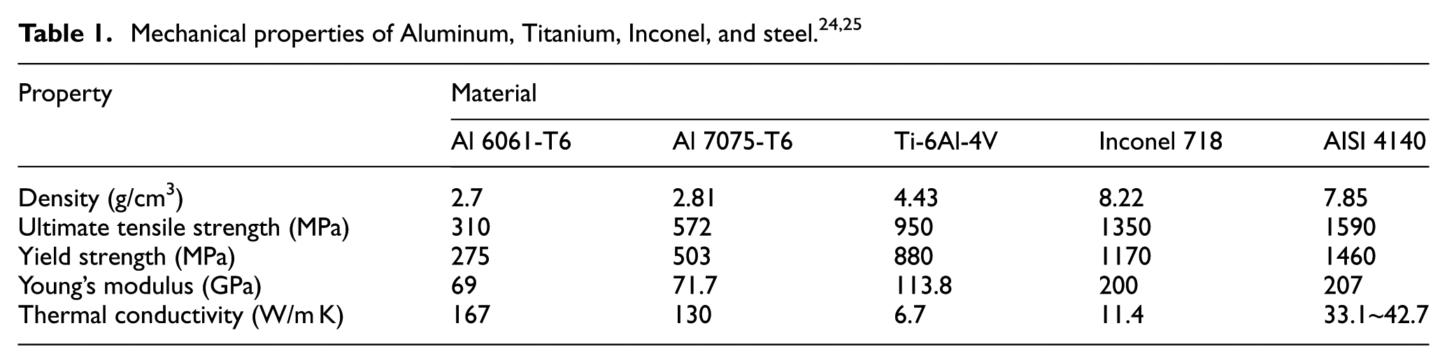
Mechanical properties of Al 6061-T6 compared to other prospective materials are shown in Table 1. It can be noted that Al 6061-T6 has lowest density, Young’s modulus, yield and ultimate tensile strength, but highest thermal conductivity compared to other alloys.
Analysis of the formation and type of chips produced is used to characterize the machining operation. 9 In machining, the chip morphology analysis provides information about cutting forces, cutting temperatures, chatter stability, workpiece surface/subsurface quality, and tool life.10,12,26,27 Chips produced during machining are generally classified into four categories based on their geometric shapes, that is, continuous, BUE, serrated, and discontinuous chips. 6 The morphology of chips which are produced during HSM is observed to be serrated for ductile materials. 6 Cutting forces, temperatures, tool wear and tool failure, quality of surface finish, and accuracy of machined component affect the initiation of the serrated chips. Xu et al. 28 developed an analytical model to predict the influential parameters including cutting force, thrust force, chip thickness, shear angle, friction angle, tool–chip contact length, length of shear plane, and width of the first shear zone during HSM of Al 6061-T6 alloy. Cutting speed (v) and feed rate (f) were set in the range of 100–1900 m/min and 0.06–0.15 mm/rev, respectively. It was found that orthogonal machining combined with analytical model may obtain chip formation parameters during HSM by avoiding the safety risk involved in quick-stop tests. Under given cutting conditions, chips were found to be mainly continuous, curl, or discontinuous. It was further observed that the chip thickness, friction angle, width of first shear zone, and length of shear plane decreased with increasing in the cutting speed, whereas the shear slide distance and shear angle increased.
Several studies have been conducted to model machining process with different combinations of workpiece and tool material; however, no research has been cited for machining of Al 6061-T6 specifically at high cutting speeds up to 2000 m/min and feed rates of 0.4 mm/rev. During the current research, tool wear was found to be negligible at such higher cutting conditions. This research uses the Johnson–Cook constitutive model and considers JC parameter sets determined by earlier researchers1,2 and investigates their application for assessing the machinability of Al 6061-T6 alloy by predicting the cutting forces and the chip morphology at low-, medium-, and high-speed cutting conditions. Experimental results show a sudden drop of cutting forces at higher cutting conditions due to a non-linear effect produced by strain hardening and thermal softening. A coupled thermo-mechanical analysis using Abaqus/Explicit finite element code was carried out for various cutting conditions. FEM predictions showed good overall agreement with the experimental results for selected machining conditions.
Materials and methods
Experimental setup
Cylindrical work pieces of aluminum Al 6061-T6 were machined using uncoated cemented carbide inserts (CCMW 09 T3 04 H13A) mounted on a SCACL 1616 K 09-S tool holder. Both the inserts and the tool holder were supplied by Sandvik. 29 The selected inserts were uncoated, plain cutting inserts having 0° rake angle and 7° clearance angle. The inserts did not have a chip breaker.
In the present research, all experiments were conducted on ML-300 Computer Numerical Control (CNC) Turning Machine manufactured by YIDA Precision Machinery Company, Taiwan. The maximum spindle speed of the machine was 3500 r/min. A modified OTT method has been used to perform orthogonal cutting which is based on the methodology adopted by different researchers.30–32 The workpiece was machined from Al 6061-T6 forged solid bar, as shown in Figure 1. The workpiece consisted of concentric rings, each having a thickness of 4.1 mm. The cutting tool was kept perpendicular to the land between grooves. 31 The thickness of concentric rings of workpiece was selected to adhere to the mandatory condition of the orthogonal machining, which dictates that the length of the cutting edge of the inserts (9 mm) should be greater than the wall thickness of the tube (4.1 mm). As the length of cutting edge of tool (9 mm) was greater than width of land being cut, there were only two machining parameters (cutting speed and feed rate) which were controlled in different experiments. It has been observed that the two cutting parameter are important for many critical responses in machining such as tool life, surface roughness, cutting temperatures, and production time.33–36
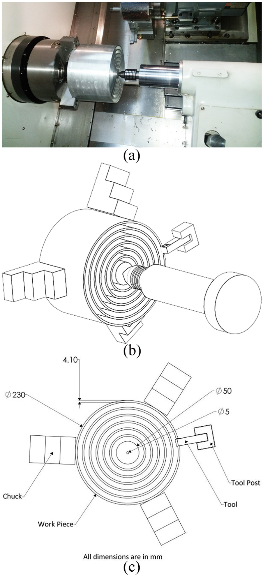
(a) Experimental setup of Al 6061-T6, (b) isometric view of experimental setup, and (c) front view of experimental setup.
The maximum longitudinal length of the grooves machined to produce concentric rings was 50 mm. The workpiece was held between the three jaw chuck and tail stock to improve rigidity during machining. The cutting forces were determined using a novel technique by measuring the power input of the CNC machine. This is explained in detail in a later section. Chips produced during the machining process were collected and analyzed to determined chip thickness and shear angle. Orthogonal machining experiments were carried out at various combinations of speed and feed rate, which were determined after a design of experiments study. These are explained in detail in the next section.
A full-factorial design of experiment (DoE) was developed (with 32 machining trials), and each trial was repeated three times to ensure the repeatability of the experimental results. Cutting experiments were conducted with cutting speeds between 250 and 2000 m/min with four different feed rates (i.e. 0.1–0.4 mm/rev) as shown in Table 2.
Design of experiment showing various cutting conditions.

Measurement of cutting forces
Cutting forces can be measured by a force dynamometer, a force transducer, a load cell, or by measuring power consumption. 35 Different sources4,35,37–39 have suggested that the cutting forces can be approximated through measuring specific cutting energy (SCE). However, no study in literature has been undertaken in the past to perform such calculation. Moreover, the value of SCE in previous researches has been considered either as a constant or over a range. However, the value of SCE for a material varies with different cutting conditions even when the machining process is kept the same. 40 The current research work employs a methodology based on measurement of power consumption to estimate cutting force (Fc) with the help of SCE at different cutting conditions. Furthermore, the obtained values of Fc using power meter have also been compared with the results of cutting forces obtained through piezoelectric force dynamometer published by Xu et al. 28 and insignificant difference has been observed. In the current research, power consumption methodology was adopted for cutting force measurement (Figure 2), where Yokogawa clamp-on power analyzer CW 240-F was used. A two-cycle approach, that is, air-cut cycle (Pair) and actual-cut cycle (Pactual), was incorporated for each experimental trial. Average power consumed for each cycle gave Pair and Pactual, respectively, and the difference between Pair and Pactual given in equation (1) provided the power necessary to remove the material (Pcut) during a particular machining cycle 25


(a) Yokogawa clamp-on power analyzer CW 240-F and (b) current and voltage measurement probes (clamps) installed at the main bus of CNC machine.
SCE, which is the energy consumed to remove a unit volume of material (N m/mm3 or J/mm3), was obtained by normalizing power consumption (Watts) of MRR (mm3/s) and is calculated using equation (2) 25

SCE considers only Pcut, that is, the power required to remove unit volume of certain materials (Al 6061 in this case) and does not take into account the make, type, and efficiency of different component of machine tool. SCE is simply the ratio of the cutting force (Fc) to the projected area of the cut (product of w and to) and is related to cutting force (Fc) by the following equation (3)4,35,37–39

Shear angle measurement
Chips at all cutting conditions were collected and processed through grinding and polishing for further metallographic analysis using Optika optical microscope. Thickness and shape of all chips were noted and chip thickness ratio (r) and shear angle (φ) were determined. Shear angle was calculated using equation (4)25,41–43

As the rake angle (a) of the insert used in this current research is 0°, equation (4) can be rewritten as25,42

Finite element modeling
Material model includes high deformation, strain rate, and temperature effects as well as friction model which can be temperature, sliding speed, and pressure dependent. A separation criterion is required as input parameters to perform a finite element study of the machining process.4,44 In this research, four-node bilinear, reduced integration with hour glass control, coupled temperature–displacement plain strain elements were used.
Material model
The JC which is most commonly used material model for high strain rate deformations was used for the workpiece material. The JC plasticity model includes analytical forms of the hardening law, rate, and temperature dependence. The model can be written as equation (6)16,17

The first set of brackets shows strain effect and provides stress as a function of strain, whereas the second set of brackets show the effect of strain rate on yield strength of the material. The third set of brackets show thermal softening effect on the yield strength.3,42,45,46 The values of the JC material model used in this work were based on two different researches and are given in Table 3. This approach was used to show that the results obtained using JC material model may differ due to the selected values of the parameters, even for the same material.

Damage is defined as a process which gradually reduces the load carrying capacity resulting in the complete failure of the material. 49 Johnson–Cook damage model has been employed along with the Johnson–Cook plasticity model, which is based on the value of equivalent strain at element integration points. 46 Failure is assumed to occur when the damage parameter exceeds a value of one. Johnson–Cook damage and failure models follow a cumulative law and is written as equation (7) 17

Equivalent plastic strain

The values of the damage constants, Di (where 1 ≤ i ≤ 5) for Al 6061-T6 alloy are taken from published literature1,47,48 and are shown in Table 4.

Friction at tool–chip interface is one of the most critical input parameter that affect major dependent variables including cutting forces, chip morphology, residual stresses, and temperatures. 46 Therefore, determination of accurate friction conditions is of considerable importance for finite element investigation of machining operation. Coulomb’s friction law is the simplest way of characterizing the tool–chip interface where coefficient of friction is assumed to be constant over the entire rake face of the cutting tool. 50 The coefficient of friction, µ is the ratio of the cutting force parallel to the tool’s rake face and the force normal to the rake face. In the current work, Coulomb’s friction law was used with coefficient of friction taken as 0.25 for low and medium cutting conditions.48,51 The coefficient of friction has been modified for HSM conditions as recommended by past researchers52–54 by reducing its standard value of 0.25 to 0.10. Coulomb’s friction law can be expressed by equations (9) and (10) as given below 55


The above formulations show that the friction between the tool–chip interfaces is sliding when the frictional stress is below
FEM
A 2D coupled thermo-mechanical FEM has been developed in Abaqus/Explicit, meshing details and boundary conditions are shown in Figure 3. Both cutting tool and workpiece material were set as 2D plane strain (deformable), and the tool dimensions were modeled according to the tool used for the experimental work, that is, 0° rake angle and 7° clearance angle.42,46 The workpiece material was fixed in x and y directions, whereas tool was given velocity in the x direction. Modeling of the cutting tool as deformable material helps to obtain necessary cutting process variables to analyze the stresses that are present in the tool and to get the required cutting process variables for the latter tool wear measurement.56,57 Moreover, tool material being much harder than the workpiece material, its deformation remains in the elastic range. 58
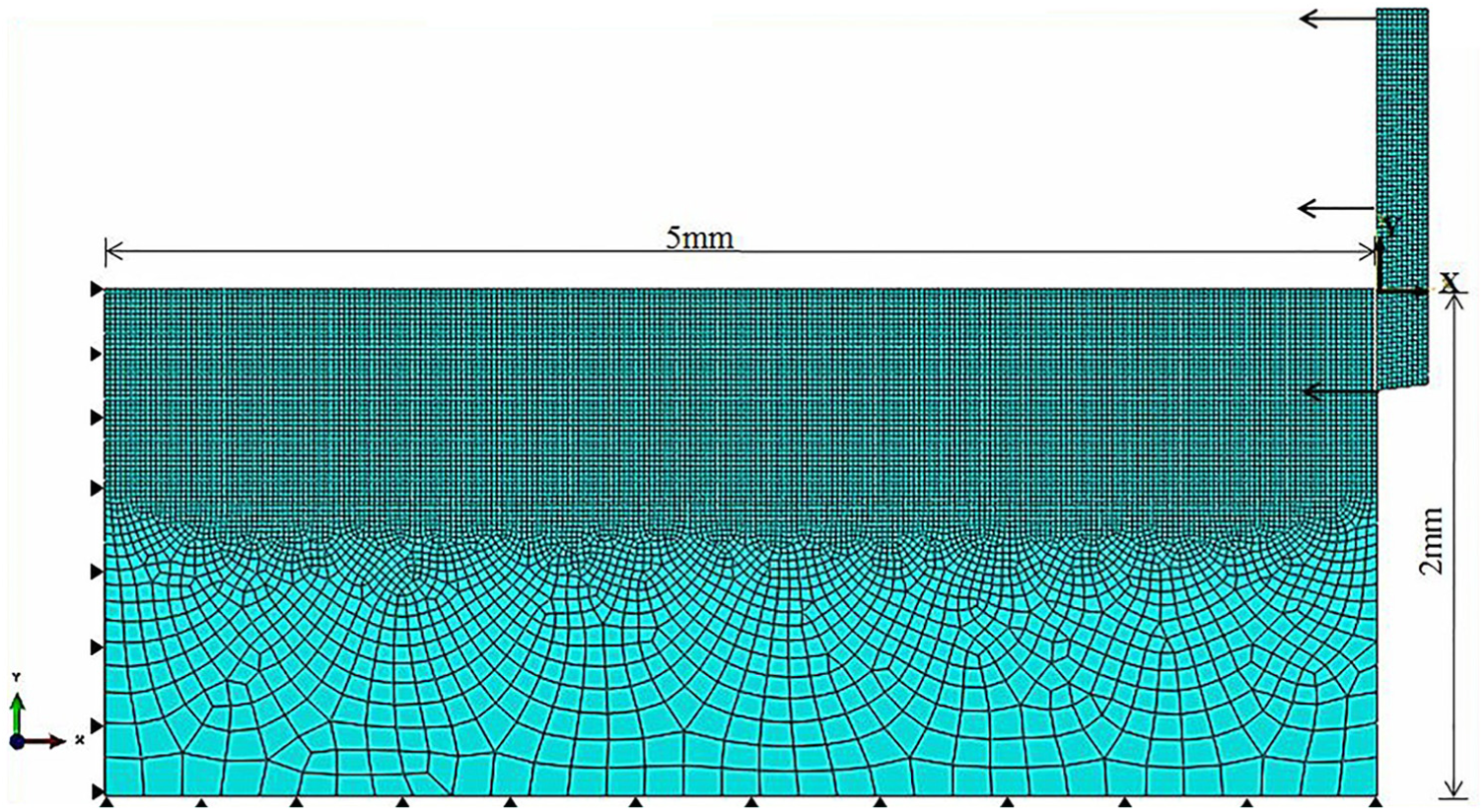
Finite element meshing and boundary conditions showing fixed workpiece and tool velocity along x-axis.
Methodology validation
Validation of power meter measurements for cutting force
The experimental data of cutting forces measured using piezoelectric dynamometer, available in literature, are limited to cutting speeds up to 1900 m/min at feed rate of 0.15 mm/rev. 28 In case of maximum feed rate of 0.31 mm/rev, the available cutting data are at speeds of 1539 m/min. 2 This work extends the body of research by adopting a new methodology of using power meter that was first validated and subsequently used for speed and feed rate combinations up to 2000 m/min and 0.4 mm/rev, respectively. The results were verified by comparing with the relevant data from previous research. 28 Furthermore, the data of the cutting energy were further processed to obtain cutting forces needed to validate the model presented in this research. Once this was completed, a DoE was conducted, and full-factorial experiments were carried out using the power meter approach to obtain cutting forces. As already discussed, the cost of a power meter is much lower as compared with a dynamometer, and the setup is comparatively easy to install as compared with a dynamometer installed/incorporated on the tool post/turret/workpiece. Validation of the cutting forces obtained through power meter against the published literature that were measured using piezoelectric dynamometer is shown in Table 5.
Verification of cutting forces through power consumption method with the published results. 28

The experimental conditions were varied from low- to high-speed machining range for a feed rate of 0.09 mm/rev. The maximum error between the cutting forces from literature and that calculated from energy measurement was found to be 3.29%.
Validation of numerical model
JC material constants from Lesuer et al. 1 (M1) were first used in the simulation of orthogonal machining of Al 6061-T6 alloy to validate the FE model. The results obtained were then compared with the experimental results published by Xu et al. 28 Figures 4–6 present the results of cutting forces, chip thickness, and shear angles obtained from FE model and observed by Xu et al. 28 Chip thickness (tc) was found to decrease by increasing cutting speed (v) whereas chip thickness (tc) increased with increasing feed rate (f). On the contrary, an increase in the shear angle (φ) was observed by increase in cutting speed (v) and feed rate (f). These results obtained through simulation were in close agreement with the published experimental results with maximum error of 7.8% for cutting force (Fc), 14.9% for chip thickness (tc), and 8.2% for shear angle (φ). It was observed that cutting forces and chip thickness obtained through simulation were slightly under-predicted, whereas shear angles were over-estimated compared to the experimental results.

Comparison of simulated cutting force with published results of Xu et al.

Comparison of simulated chip thickness with the published results of Xu et al.

Comparison of simulated shear angles with the published results of Xu et al.
Investigation of JC parameters
Two different sets of JC parameters presented in Table 3 were used in the simulation of orthogonal machining and compared with the cutting forces (Fc) obtained from energy measurement technique. Figures 7–10 show the effect of cutting speed (v) and feed rate (f) on the cutting force, Fc. It can be observed that the JC material model parameter set suggested by Lesuer et al. 1 (referred as M1) worked well for low (v = 250–750 m/min5) and medium cutting conditions (v = 750–1500 m/min5); however, the same over-predicted the simulated results for higher cutting conditions (v = 1750–2000 m/min5). Similarly, the JC material model parameter set suggested by Daoud et al. 2 (referred as M2) produced reasonably good results at the low and medium cutting conditions, but it failed to predict cutting forces at high-speed cutting conditions. The reason for this discrepancy was due to the fact that the JC material constants provided by Daoud et al. 2 were originally applicable only in the range of 363–1539 m/min and 0.07–0.31 mm/rev.

Comparison of simulated and experimental cutting forces at f = 0.1 mm/rev.

Comparison of simulated and experimental cutting forces at f = 0.2 mm/rev.

Comparison of simulated and experimental cutting forces at f = 0.3 mm/rev.

Comparison of simulated and experimental cutting forces at f = 0.4 mm/rev.
In order to improve the predictions of the numerical model, a reduced coefficient of friction was incorporated at higher cutting conditions. The results of cutting forces (Fc), chip thickness (tc), and shear angles (φ) obtained through simulation for higher cutting conditions were then compared with the experimental results. By incorporating reduced coefficient of friction, material constants provided by Lesuer et al. 1 (M1 model) and Daoud et al. 2 (M2 model), the maximum error for cutting force (Fc) was reduced to 19.1% and 23.7% compared with the earlier prediction of 36% and 41%, respectively, at higher cutting conditions. Similarly, chip thicknesses (tc) and shear angles (φ) for higher cutting conditions showed substantial improvements by incorporating reduced coefficient of friction, producing serrated chips at higher cutting conditions. After taking measurements at five different peak positions of maximum thickness and averaging, the experimental and simulated results of chip thicknesses and shear angles are given in Figures 11 and 12. It can be observed that the chip thickness decreases with increasing cutting speed. Continuous chips were produced during the cutting process at lower cutting speed, for example, 250 m/min due to homogeneous deformation, whereas higher cutting speeds produced serrated chips due to adiabatic heating effect.6,11,59,60

Comparison of simulated and experimental chip thicknesses (tc) using Lesuer et al. M1 model.
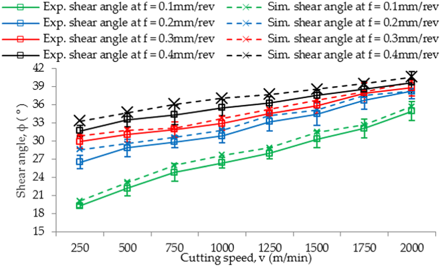
Comparison of simulated and experimental shear angle (°) using Lesuer et al. M1 model.
Figures 13 and 14 show chip morphology obtained through machining experiments and FEM simulations at lowest and highest cutting conditions. The shape of the collected chips were found to be continuous curling and serrated, respectively, at lower and higher cutting conditions. The chip thickness and morphology obtained from simulation, at various points along the length of the chip, is in close agreement with the experimental measurements.

(a) Experimental and (b) simulated chip morphologies at v = 250 m/min, f = 0.1 mm/rev.

(a) Experimental and (b) simulated chip morphologies at v = 2000 m/min, f = 0.4 mm/rev.
Discussion
Cutting forces obtained through power meter and numerical model were first validated with the published experimental results obtained through force dynamometer 28 and found in close agreement. Cutting experiments were then carried out at low-, medium-, and high-speed machining, and the results obtained through power meter were compared with the results obtained through numerical simulations. Two sets of parameters for JC material model from literature were investigated under all cutting conditions. Yield strength of Al 6061-T6 decreases exponentially with the increase in the temperature after 200°C 21 as shown in Figure 15. This can be attributed to the non-linear thermal softening effect with the increase in the temperature. This non-linear thermal softening effect has not been captured properly, as the thermal softening of the JC material model follows a power law with a constant value of thermal softening coefficient, m. At high cutting speeds, the thermal softening may be occurring at a rapid pace that is not predictable using a constant value of thermal softening coefficient, m.

Effect of temperature on the mechanical properties of Aluminum alloy 6061-T6.
At lower feed rate of 0.1 mm/rev, both experimental and simulated cutting forces showed little variation with increasing cutting speed, whereas increase in the feed rate (f) from 0.1 to 0.4 mm/rev has a substantial effect on the cutting forces at all cutting speeds. This effect may be due to the increase in the cutting area and removed material volume, by increasing feed rate. 43 Moreover, Xu et al. 28 observed that shear angles were increased by increasing cutting speed. As a result, shear slip plane area in the primary deformation zone decreases leading to reduced cutting force. 28 The dissipation of heat through chips is facilitated at higher cutting speeds due to higher thermal conductivity of aluminum alloys and short time available for the dissipation of heat into the workpiece material. 61 Moreover, plastic strain rates during HSM become high enough to produce considerable heat in the primary shear zone which is unable to be dissipated rapidly into the base workpiece material due to short contact time. 2 As a result, thermal softening of the material occurs due to quasi-adiabatic condition. 13 Wu and To 11 also deduced that the adiabatic heating effect which occurs during HSM causes thermal softening of the material and produce serrated chips. 11 Therefore, thermal softening along with reduced coefficient of friction was incorporated at higher cutting conditions which resulted in decreased cutting forces.
It has been shown that the two sets of JC material constants provided in literature showed good agreement with the experimental results at low and medium cutting speeds and feed rates. However, the JC material model failed to predict the cutting forces at high cutting speeds using either set of JC constitutive parameters. This showed the existence of a material behavior that does not exist at lower or medium cutting speeds. Two factors were considered responsible for the change in cutting forces at higher cutting speeds: change in coefficient of friction and thermal softening. By reducing the coefficient of friction, the prediction of the numerical model may be largely improved. Similarly, a constitutive plasticity model with temperature dependent thermal softening coefficient may also help improving the cutting force prediction at higher cutting speeds.
FEM analysis of machining operation provides a feasible alternative process in order to analyze chip formation mechanism during HSM. The shape of the chips collected gave information about the suitability of the cutting parameters and surface finish of the machined component. The maximum error between experimental and simulated chip thickness (tc) was observed as 19.5% at v = 1250 m/min and f = 0.1 m/min, as shown in Figure 11. The reason for this discrepancy is attributed to the fact that machining at CNC being intermittent process produces unsteady chips which could have caused the variation in the measurement. Chip thickness decreased with the increase in the cutting speed, whereas the same increased with increase in feed rate. This was due to decreased shear angle at higher cutting speed or feed rate. Chip thickness decreased with increase in cutting speed and increased with increased feed rate due to decreased shear angles. Substituting chip thickness (tc), feed rate (f), that is, uncut chip thickness (to) and rake angle (α) in to equations (4) and (5), shear angles were calculated. The comparison of experimental and simulated results showed that predicted chip thicknesses were slightly less than the actual chip thicknesses, whereas predicted shear angles were slightly higher. Shear angles (φ) were increased with the increase in cutting speed and feed rate. Maximum error between experimental and predicted shear angles was found to be 8% at v = 250 m/min and f = 0.2 mm/rev. Serrated chips were found to produce at higher cutting speeds and feed rates both experimentally and numerically. B Wang and Z Liu 6 pointed out thermal softening results in the reduction of flow stress causing formation of serrated chips.
Conclusion
It can be concluded that at cutting speeds of 1750/min for aluminum-based alloys, increased thermal softening and reduced coefficient of friction play a dominant role in numerical simulation models.
Energy consumption drops significantly at cutting speeds starting from 1750 m/min. Maximum MRR can be achieved at these conditions.
Under low (v = 250–750 m/min) and medium cutting conditions (v = 750–1500 m/min), feed rate plays a dominant role possibly due to increase in the cutting area and removed material volume, whereas the role of cutting speed is pronounced during higher cutting conditions, that is, HSM due to short contact time and adiabatic heating condition.
The JC based on material constants provided in literature showed good agreement with the experimental results at low and medium cutting speeds and feed rates. At higher feed rate and cutting speed decrease in the coefficient of friction showed improved agreement with experimental results.
The approach of measuring electric power to calculate cutting forces is validated using published data. This approach offers the benefit of using low-cost technology as compared to the use of more expensive piezoelectric force dynamometer. The degree of accuracy is also comparable with the results obtained using force dynamometer.
Footnotes
Appendix 1
Handling Editor: Min Zhang
Declaration of conflicting interests
The author(s) declared no potential conflicts of interest with respect to the research, authorship, and/or publication of this article.
Funding
The author(s) disclosed receipt of the following financial support for the research, authorship, and/or publication of this article: This research was funded by the Higher Education Commission (HEC), Islamabad, Pakistan, under the indigenous 5000 PhD fellowship program, Batch-VII (Eg7-046).