
Abstract
Autonomous underwater vehicle is a class of intelligent robots, which has been widely used in ocean observatory. Inductive power transmission is a good way to supply power and extend the working endurance of autonomous underwater vehicle. The power transfer characteristic depends on the electromagnetic actuator. A novel electromagnetic actuator has been proposed for different traditional autonomous underwater vehicle docking applications in this study. At first, the structure of electromagnetic actuator and assembled configurations for autonomous underwater vehicle submerged docks was given. Then, the mutual-coupling circuit and reluctance model were built. At last, in order to verify and test this electromagnetic actuator’s power transfer characteristics, an underwater test setup was built and used in both laboratory experiment and in a modeled autonomous underwater vehicle power cabin. The test results showed that the novel electromagnetic actuator could reach the highest power transmission efficiency of 78.1% at the frequency of 115 kHz, while the output power of inductive power transmission system is 75 W at 5 mm gap in working condition. Thus, it is suitable for autonomous underwater vehicle power feeding.
Introduction
At present, intelligent robots are widely used in various applications, and their use has been promoted in traditional industrial purposes and also in specific operation circumstances, such as aerospace and underwater. Autonomous underwater vehicle (AUV) is a class of intelligent robots which depends on self-carried power (usually battery or fuel for engine) and self-control ability to navigate and execute the task underwater. AUV plays an important role in ocean observatory. However, the working range of an AUV is severely limited by the battery capacity. In recent years, both AUV docking technology, 1 and scientific seafloor observatory cabled networks 2 have seen advancements. Thus, charging AUVs underwater with the power obtained from seabed cable or energy conversion from hydrokinetic current, tide, or wind are good ways. 3 The traditional wet conductive connectors, which link the AUV power supply equipment and seafloor observatory networks, are prone to arcing and suffer seal wear. The maintenance and cost becomes too high for ocean observatories. In addition, wet conductive connectors often fail because of low reliability. 4
Inductive power transmission (IPT) system transfers power by electromagnetic coupling and realizes non-physical contact between the energy supplier and load. IPT systems have been broadly used in different applications, such as power charging for electrical vehicles,5,6 rotating separated equipments, 7 mobile household electrical appliances, 8 and some bio-medical electronics. 9 Since the IPT system overcomes several intrinsic defects of wet-mate connector, more and more concentration has been paid on its utilization in AUV undersea power feeding applications. Kojiya et al.10,11 designed an contactless power supply device for underwater vehicles, this device could transfer power of 500 W or 1000 W, and the power transmission efficiency was as high as 90%. Granger 12 developed an IPT system and utilized it in an unmanned underwater vehicle (UUV) named “Proteus”; test results showed that the system operated well in AUV launch and power feeding applications. In order to supply power to underwater mooring profiler, McGinnis et al. 13 promoted an wireless power transfer system; in this system, under the 0- to 5-mm gap working conditions, the power transfer efficiency was above 70% with the maximum power of approximately 240 W.
Usually, the IPT system’s power transmission capacity and performance are decided by electromagnetic coupled actuators. In marine working environment, the IPT system suffers from variable gap and misalignment between electromagnetic couplers, which are caused by docking errors and ocean current disturbance. It often results in low coupling coefficient k and brings in great challenges to the coupled actuator design.
Kojiya et al.10,11 promoted a specially structured electromagnetic coupled actuator for IPT system for underwater vehicles, in which the coil conical in shape and winded was twined around the actuator to keep it in a relatively stable position in undersea power feeding application. Cheng et al. 14 studied and compared the transfer characteristics of semi-closed and non-closed actuators by means of simulation analysis and experiment; the conclusion showed that semi-closed magnetic core has better transfer performance. In the study of IPT system for “Proteus” UUV, the electromagnetic actuator was a circular arc; 12 the structure enabled it to be utilized in underwater docking or as a charging pod, which is designed for AUV recovery and power feeding. In 2013, Zhou et al. 15 proposed a non-contact power transfer system, and a PM ferrite core was selected in the electromagnetic coupled actuator’s design. This system could achieve 300 W power transfer with an efficiency of above 85% under 5-mm gap working condition. Lin et al. 16 proposed a new inductive coupling power transfer (ICPT) system, in which the actuator’s coil was winded around the AUV’s hull. Kan et al. 17 presented a three-phase wireless power feeding actuator for lightweight AUV; in the study, three power transmitters and receivers were placed in 120° angle and 1.0 kW power transfer demand was met. Wang et al. 18 designed a pack of electromagnetic actuators for an IPT system: the primary and secondary parts were mounted on the submerged docking base and front-head section of AUV, respectively.
There are two main ways of AUV docking: the vehicle entered the docking cage 19 which had a shape similar to the bell part of the trumpet, and the AUV docking like a helicopter landing. 20 Both the docking way target for tapered steering cover and cage and the docking method target for underwater platform have seen advancements. In this study, a novel electromagnetic actuator is proposed, and the structure aims at two main AUV docking applications. At first, the structure of electromagnetic actuator and assembled configurations for AUV submerged docks are given. Subsequently, the proposed mutual-coupling circuit and reluctance model with compensation methods were introduced. Finally, to further study the transfer characteristics of novel electromagnetic actuator, an underwater test setup both used in laboratory experiment and modeled AUV power cabin section was built. The test results validate the proposed concept of proposed electromagnetic coupled actuator, and the study could reach a conclusion that novel coupled actuator is suitable for AUV power feeding.
Structure and assembled configuration of novel electromagnetic actuator
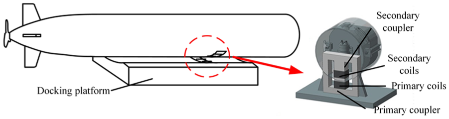
The novel electromagnetic actuator is called the reshaped EE coupler, because it was modified from the EE structure electromagnetic coupler. In AUV power feeding applications, the electromagnetic actuator was designed to be mounted on the power cabin part of AUV. Figure 1 presents its structure and fixed configuration. Also, in the helicopter landing docking application, the electromagnetic actuator is suitable (Figure 2).

Structure and fabricated construction of novel electromagnetic actuator for cage-liked docking application.
Structure and fabricated construction of novel electromagnetic actuator for helicopter landing platform docking application.
This novel electromagnetic coupler is manufactured from usual EE coupler. In design process, the pillar part of “E” is modified and manufactured in accordance with the AUV’s boundary dimension. This study mainly aims at inductive power feeding for 200 mm-diameter cylindrical AUV. This pair of actuator is divided into primary and secondary parts. The former is fixed on the submerged docking cage or platform, and the secondary part is mounted on the AUV’s battery cabin section. To meet the docking demand, the pillar of “E” in the primary part is manufactured concaved, but the secondary side “E” is bulging. The novel electromagnetic actuator is made of ferrite material marked “LP4 Mn-Zn,” whose relative permeability is approximately 2300. To protect the electromagnetic coupler, the insulative rubber-made shell was chosen to manufacture secondary electromagnetic coupled actuator part. In comparison with the coupler assembled on the front section of AUV, 18 the novel electromagnetic coupler has larger coupled area. Since in AUV docking applications, roll-aberrancy to AUV’s axis and docking errors are often inevitable, the design provides larger coupled area that allows better tolerance to misalignment in AUV charging application. On the other hand, in AUV design procedure, the navigation module is generally installed on the front-head section of the AUV. In order to avoid the infaust influences to navigation system, in general, we do not propose to design the additional magnetic devices on the head part of the AUV. If designers have to fix the magnetic devices on AUV front-head part, magnetic field calculation and assess of magnetic affect for instrumentation located inside the AUV are essential and rigorous. 17
In comparison with coupled actuators mentioned above,10–12,14–17 the electromagnetic actuator proposed in this article has a simple and reliable structure which is adaptable to different docking approaches. The actuator is manufactured based on EE coupler and fit with the configuration of AUV and docking station. With simple fixed process, it could be installed and in dimensional coordination with AUV and submerged docks, any changes in AUV are unnecessary.
Reluctance model and mutual-coupling circuit model
Reluctance model
In some studies,15,18 the flux lines and paths of EE coupler, PM coupler or some other similar structure couplers have been studied; in this study, great attention was paid to the novel electromagnetic actuator.
The flux line distribution in electromagnetic coupled actuator could be obtained by means of theoretical and finite element analysis methods. Figure 3 demonstrates the distribution of flux lines in the actuator. Figure 4 exhibits main flux path and leakage flux path in the magnetic coupler.

Flux lines distribution in the novel electromagnetic coupled actuator.

Main flux and leakage flux paths in the magnetic coupler.
From the flux lines distribution result, the main flux transfer through the magnetic circuit and the leakage flux paths were around the electromagnetic coupled actuator.
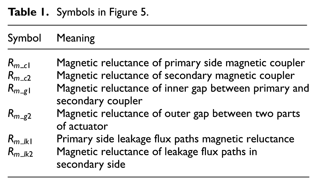
To deduce the equivalent magnetic circuit, a proper magnetic reluctance was utilized. Figure 5 illustrates the equivalent magnetic circuit. According to magnetic circuit theory, length of flux path, cross-sectional area, and material permeability decide the magnetic reluctance’s value. As Figure 5 shows, the equivalent magnetic circuit consists of three different sub-loops,

Equivalent magnetic circuit of electromagnetic coupled actuator.
Symbols in Figure 5.
Mutual-coupling circuit model
Because in underwater applications, the primary and the secondary parts are not in contact, the IPT system operated in loosely coupled working condition. The equivalent circuit model was introduced to illustrate the magnetic coupling actuator; an ideal transformer and a magnetizing circuit made up the model. It is shown in Figure 6.
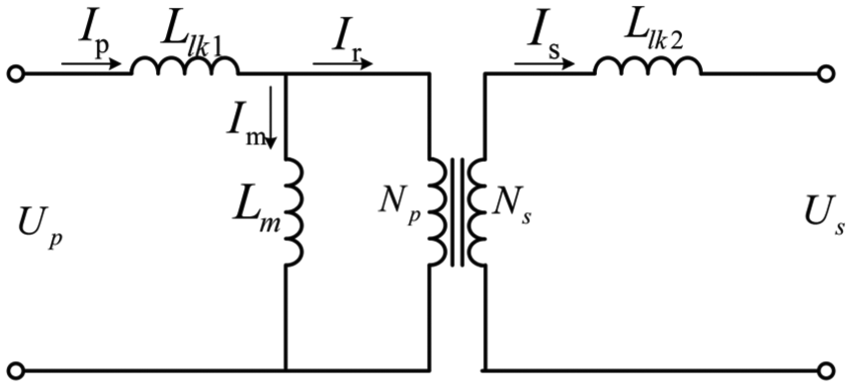
Equivalent circuit model of electromagnetic coupled actuator.
In Figure 6,
In the study, secondary parallel (SP) compensation topology was selected in the IPT system. In the compensation topology, a series capacitance linked into the primary circuit and a parallel capacitance was selected in the secondary circuit. Because it could surmount drawbacks of low transferring power and efficiency in wireless power transfer system.
21
Thus, omit the resistance of conductor wire, the mutual-coupling circuit modeling was deduced from Figure 6. The mutual-coupling circuit model of novel electromagnetic coupled actuator is illustrated in Figure 7.
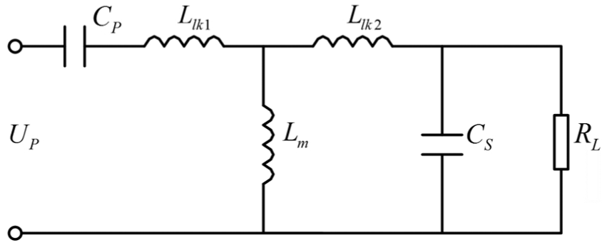
The mutual-coupling circuit model of electromagnetic coupler.
Experimental verification
Both an underwater IPT prototype system and AUV prototype modeled power cabin assembled with the electromagnetic actuator were built to verify the power transfer characteristics of this novel electromagnetic coupled actuator. The wireless power transmission prototype system is made of 5 parts: direct current (DC) power supply, high frequency inverter, electromagnetic actuator, alternating current (AC)/DC module, and electronic load. Figure 8 exhibits the components of the prototype system; the oscilloscope was used to measure the waves of voltage and current. Figure 9 is the AUV prototype modeled power cabin assembling the electromagnetic actuator.
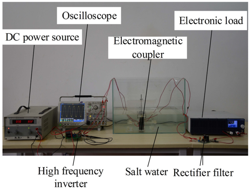
IPT prototype system.

AUV prototype modeled power cabin assembling the electromagnetic actuator.
In the test, the gap between two parts of the electromagnetic coupled actuator was chosen as 5 mm, and the voltage of DC input power is 96 V. The laboratory electromagnetic actuator and the magnetic coupler assembled in the AUV modeled power cabin were tested. The working frequency ranged from 40 kHz to 120 kHz every 5 kHz. The current and voltage waves and power transmission efficiency results are demonstrated Figure 10.

Voltage and current waves.
In Figure 11, the test results of IPT efficiency show that the novel electromagnetic coupled actuator has good performance. When the output power of IPT system is 75 W, the power transfer efficiency varies with working frequency. At first, the power transmission efficiency is increasing with operating frequency from 40 kHz to 60 kHz, then the efficiency drops slightly and fluctuates as frequency increases; the system reaches the highest efficiency of 78.1% at the frequency of 115 kHz. The transfer efficiency of actuator assembled in the modeled AUV power cabin is slightly less than the actuator without fixed configuration because the eddy loss of IPT system in the AUV surface cause power loss.
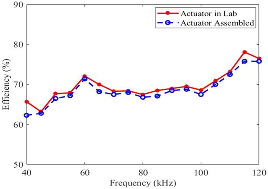
Efficiency results of different working frequencies.
Conclusion
A novel electromagnetic coupled actuator aiming both the AUV caged-targeted docking and helicopter landing docking applications was proposed in this study. The structure and assembled construction were illustrated. The reluctance circuit and mutual-coupling circuit were built for further study. In order to verify the power transmission characteristics of electromagnetic coupler, an underwater IPT system prototype was set up. Test results show this novel coupler has good power transfer ability.
Footnotes
Handling Editor: Chenguang Yang
Declaration of conflicting interests
The author(s) declared no potential conflicts of interest with respect to the research, authorship, and/or publication of this article.
Funding
The author(s) received no financial support for the research, authorship, and/or publication of this article.