
Abstract
In this article, the design of a nonrelative sliding gear mechanism for parallel axes transmission is presented. First, the general meshing line functions were actively designed for the nonrelative sliding transmission between parallel axes. The parametric equations of contact curves on the driving and driven gears were deduced by the coordinate transformations of function-oriented design of meshing line functions. The meshing between two contact curves on driving and driven gears follows the principle of space curve meshing. Based on two types of motion equations of meshing points, the parametric equations of driving and driven tooth surfaces were deduced according to the helical motion along the calculated contact curves. According to the calculation equations, two pairs of numerical examples were designed and material prototype samples were fabricated to experimentally validate the kinematic performances. After the two types of meshing line motion functions for nonrelative sliding meshing for parallel axes transmission were analyzed, a tooth contact comparative analysis was carried out between the nonrelative sliding gears with uniform motion of meshing points and involute gears, exhibiting better performances. This article introduces a new design method of nonrelative sliding gear mechanism for parallel axes transmission based on function-oriented design of meshing line functions.
Keywords
Introduction
Gear mechanisms have been invented for centuries to transmit movement and power. Limited types of tooth profile curves, such as cycloid, involute, circular arc, and parabola are used in industrial applications of traditional gears. The design and manufacture of tooth surfaces of traditional gears are based on the principle of conjugated surface meshing.1–3 Litvin and Fuentes 4 proposed basic kinematic relationships between the velocities of contact point and contact normal of conjugated surfaces.
Space curve meshing equations were deduced by Chen and colleagues,5,6 and a meshing theory of conjugated space curves was established. Using the space curve meshing theory, line gears 7 including space curve meshing wheels (SCMWs)8–10 and space curve meshing skew gears (SCMSGs)11–13 were extensively studied for microelectromechanical system (MEMS). Then, Chen and colleagues14,15 further developed the conjugated curves meshing theory including the selection of arbitrary contact vector directions, design of new circular arc tooth profiles, 16 geometric and contact characteristics of tubular meshing tooth surfaces,17–19 and sliding ratio analysis for conjugated curve gears. 20
Figure 1 shows a general design of tooth profiles for the abovementioned two types of meshing theories. First, a driving contact curve or contact surface was selected, and then, the conjugated driven contact curve or contact surface was calculated using the meshing equations of space curve meshing or surface meshing, respectively. Therefore, the meshing lines and properties were passively determined, even though they were not actively designed. However, the curvature interference and undercut limit the design of tooth profile and number, especially in the design of traditional gears such as involute and worm gears. 2 Besides, the relative sliding between tooth surfaces still cannot be entirely eliminated according to the abovementioned two types of design methods. 20 The high temperature of oil due to relative sliding led to lubrication failure, causing the transmission failure of gear scuffing and wear. Even the plastic deformation on soft tooth surface was partially caused by relative sliding.
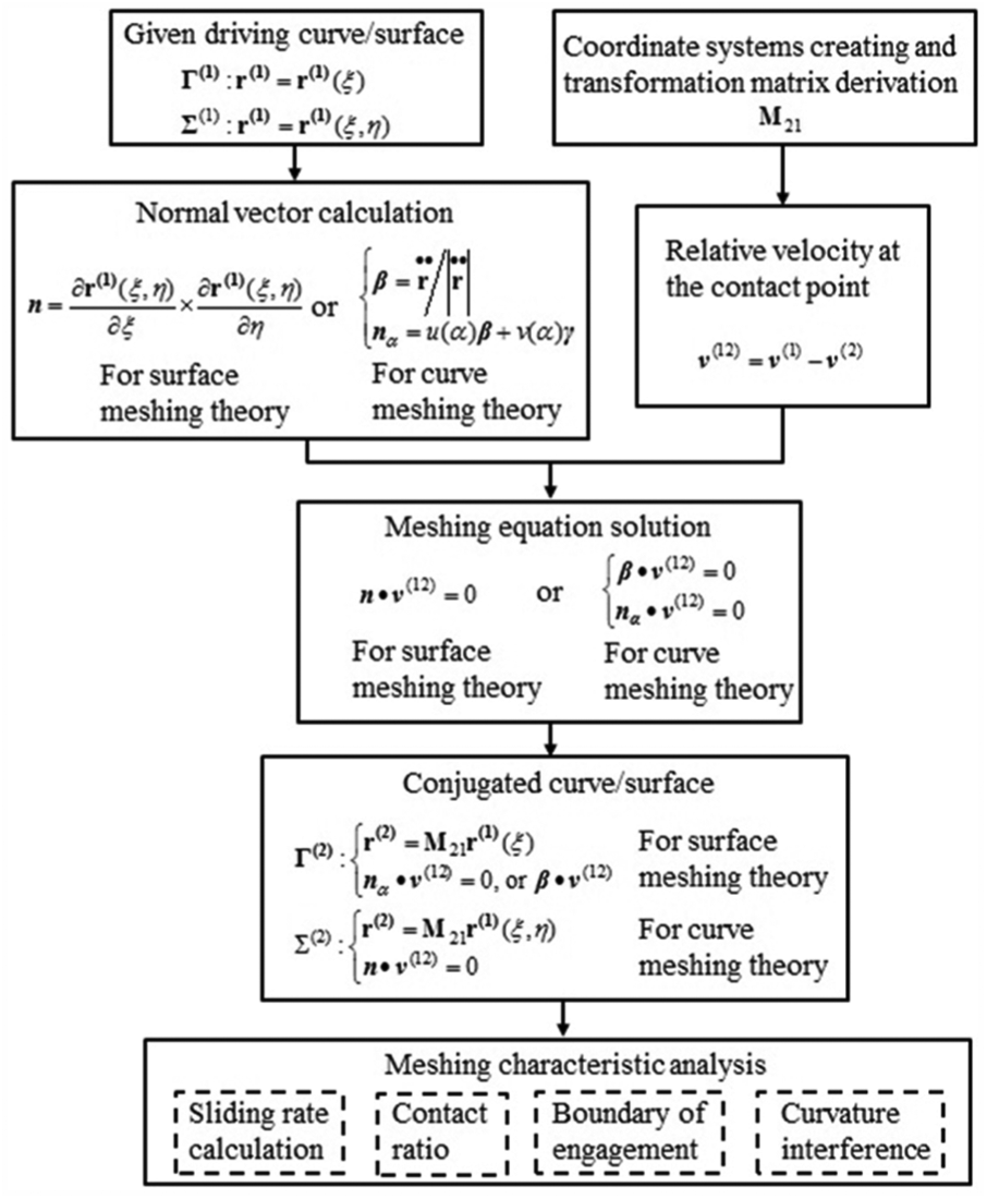
Design based on two types of meshing theories.
Based on the meshing line function-oriented design, a new design method of nonrelative sliding gear mechanism for parallel axes transmission is presented in this article. First, the nonrelative sliding meshing line functions were actively designed for the transmission of movement and power between parallel axes. Second, using the actively designed meshing line equations, parametric equations of contact curves on driving and driven gears were deduced by coordinate transformation. Next, appropriate plane circles were selected as the generatrix of the driving and driven tooth surfaces for parallel axes transmission. Finally, parametric equations of driving and driven tooth surfaces were deduced based on the helical motion of generatrix circles along the calculated contact curves, and material prototype samples were fabricated to experimentally validate the kinematic performance of newly designed nonrelative sliding gear mechanism.
Meshing line function-oriented design for a nonrelative sliding gear mechanism
An essential condition of nonrelative sliding gear surfaces is that the relative velocities of all the meshing points on the meshing line should be zero. In fact, the set of all the meshing points with zero relative velocities is the tangent line of two cylindrical axodes for parallel axes transmission. Therefore, the nonrelative sliding gear mechanism for parallel axes transmission exists as long as the tangent lines of two cylindrical axodes are set as the meshing lines. Figure 2 shows the axodes, meshing line, contact curves, and meshing coordinate systems for the external gearing of parallel axes transmission. The angle between the vectors of angular velocities is

Axode, meshing line, contact curve, and meshing coordinate systems for the external gearing of a parallel axes transmission.
The meshing between two gears with a stable gear ratio should be viewed as the pure rolling of two contact curves by ignoring the elastic deformation of both tooth surfaces. Meshing point M moves continuously along the meshing line

where t is the motion parameter of meshing point M,
In the common gear mechanism of parallel axes transmission such as spur involute gears, the meshing point has a uniform motion along the meshing line. In fact, the continuous motion of meshing point M along the meshing line

where

For a uniformly accelerated motion, the motion of meshing point M along the meshing line

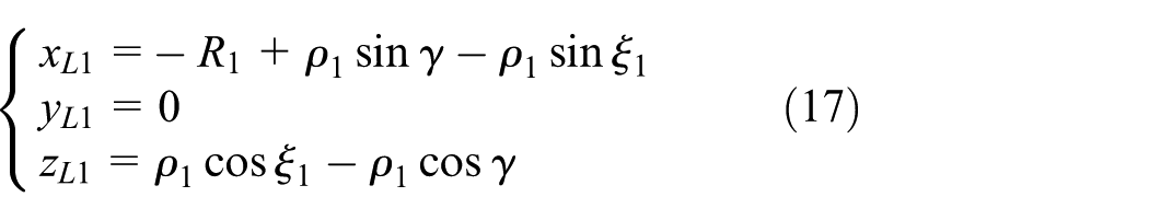
To ensure nonrelative sliding meshing, the relationship between the rotation angle of axodes and the movement of meshing point must be linear and can be expressed as equation (5)

where k is the motion coefficient, and
Parametric equations of contact curves on driving and driven gears
When meshing point M moves along the meshing line

The coordinate transformation matrices

The homogeneous coordinate transformation between the coordinate systems

The homogeneous coordinate transformation between coordinate systems

Therefore, the parametric equations of driving and driven contact curves can be expressed as equations (11) and (12), respectively

Case 1. The continuous motion of meshing point M along the meshing line

where T is the variable parameter of helix.
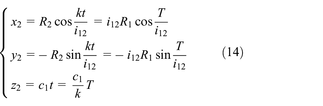
The parametric equations of equations (13) and (14) indicate that the contact curves for parallel axes transmission with a uniform motion of meshing points have the same expression as reported in Chen et al. 21 The driving and driven contact curves are both equal-pitch cylindrical helixes:
Case 2. The continuous motion of meshing point M along the meshing line


where T is the helix angle parameter.
The parametric equations of equations (15) and (16) indicate that the contact curves for parallel axes transmission with uniformly accelerated motion of meshing points are both varying-pitch cylindrical helixes, respectively.
Three orthographic views of the driving and driven contact curves of Cases 1 and 2 are shown in Figures 3 and 4, respectively. As shown in Figure 3, the contact curves on the driving and driven gears are both equal-pitch cylindrical helixes with a uniform motion of meshing points. When the motion of meshing point M changes to a uniformly accelerated motion, the contact curves on the driving and driven gears are both varying-pitch cylindrical helixes, as shown in Figure 4.

Contact curves for parallel axes transmission with a uniform motion of meshing points.

Contact curves for parallel axes transmission with a uniformly accelerated motion of meshing points.
Design of driving and driven tooth surfaces of a pair of nonrelative sliding gears
The driving and driven tooth surfaces should contain contact curves to ensure nonrelative sliding space curve meshing. A pair of driving and driven contact curves can be calculated from t using equations (13)–(16). Considering the positive and negative rotation of transmission, one tooth surface should contain at least two contact curves. One of the contact curves can be calculated using the abovementioned equations, and the other is determined by the rotation of calculated contact curve, that is, the driving and driven tooth profiles should be constructed by at least two contact curves on the driving and driven gears, respectively. In addition, there should be no interferences between the driving and driven tooth surfaces.
Chen et al. 21 reported a design method of conjugated concave-to-convex meshing circular arc helical surfaces according to the equal-pitch cylindrical helical motion of generatrix circles along cylindrical helixes. In the study reported in Chen et al., 21 the generatrix circles were located in the normal plane of cylindrical helix. In this study, the plane generatrix curves are located in a plane passing through the rotation axes and perpendicular to the bottom plane.
Design of driving and driven tooth profiles with a uniform motion of meshing points
Under a uniform motion, the contact curves on the driving and driven gears are both equal-pitch cylindrical helixes, as expressed in equations (13) and (14), respectively. The driving and driven tooth surfaces can be generated by the equal-pitch helical motion of plane curves along the driving and driven contact curves, respectively. Thus, both the driving and driven tooth surfaces can be described as equal-pitch cylindrical helicoids. If the plane generatrix curve is located in the axial cross section that cuts through the rotation axes, then there are three possible meshing types of tooth surfaces, as shown in Figure 5. Points

Three meshing types of nonrelative sliding tooth surfaces in axial section for (a) concave-to-convex meshing, (b) plane-to-convex meshing, and (c) convex-to-convex meshing.
The plane generatrix curves are concave arc circle to convex arc circle, straight line to convex arc circle, and convex arc circle to convex arc circle. Considering the meshing merits of high contact strength of concave-to-convex meshing type, the concave-to-convex circular arc profiles were introduced in this article. The generatrix circle and parameters
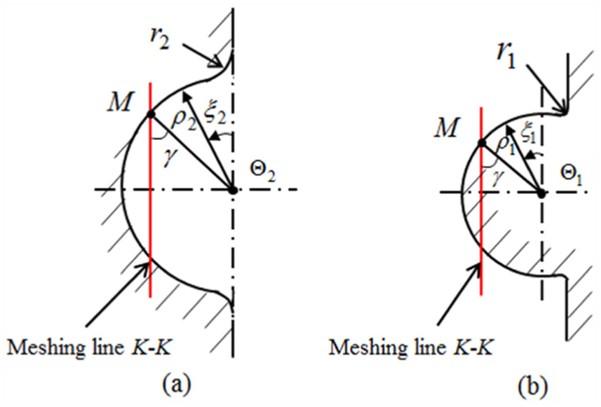
Generatrix circles and parameters for (a) driven tooth profile and (b) driving tooth profile.
By setting meshing point M to be located at point
The parametric equations of generatrix circle for the driven gear are expressed in coordinate system

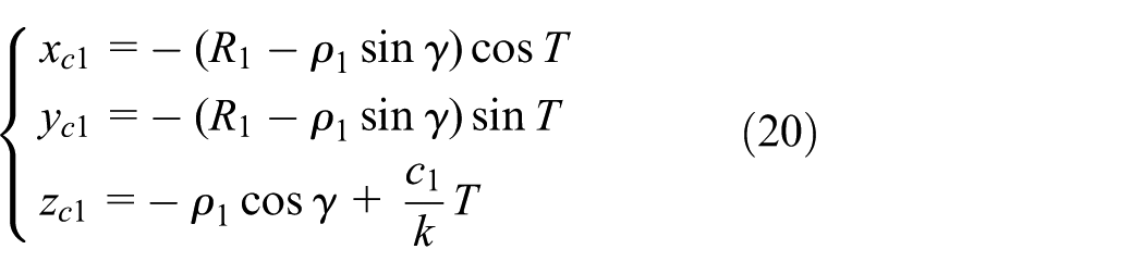
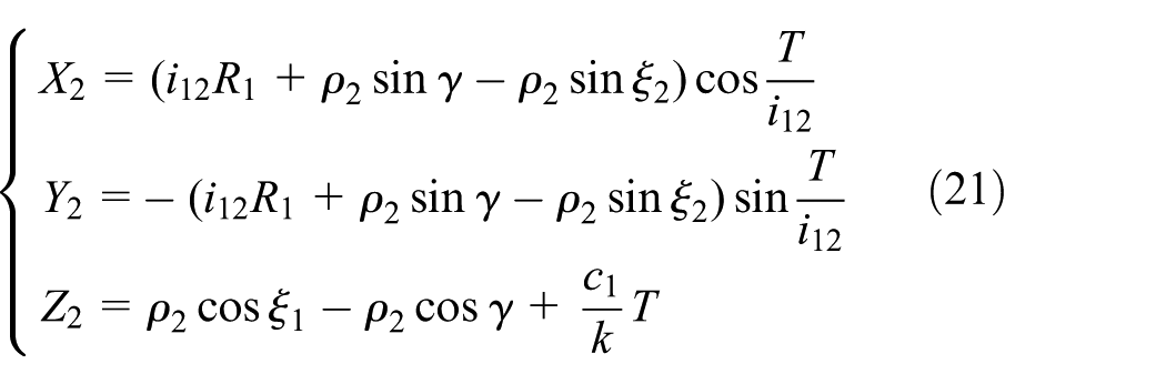
According to the right-handed equal-pitch helical motion, the parametric equations of tooth surface for driving gear can be expressed in the coordinate system

The parametric equations of tooth surface center
According to the left-handed equal-pitch helical motion, the parametric equations of tooth surface for driving gear can be expressed in the coordinate system
The parametric equations of tooth surface center

Equations (19) and (21) show that the tooth surfaces of nonrelative sliding gears for parallel axes transmission with a uniform motion of meshing points are equal-pitch helicoids, the same as that reported in Chen et al. 21
Design of driving and driven tooth profiles with uniformly accelerated motion of meshing points
In this situation, the parametric equations of generatrix circles for the driving and driven gears can be set as equations (17) and (18), respectively. According to the right-handed helical motion, the parametric equations for the tooth surface of driving gear can be expressed in coordinate system

The parametric equations of tooth surface center

According to the left-handed helical motion, the parametric equations for the tooth surface of driven gear for parallel axes transmission can be expressed in the coordinate system
The parametric equations of the tooth surface center

Equations (23) and (25) show that the tooth surfaces of nonrelative sliding gears for parallel axes transmission with uniformly accelerated motion of meshing points are varying-pitch helicoids.
Kinematics performance testing of nonrelative sliding gears for parallel axes transmission
According to abovementioned two motions of meshing points presented in section “Design of driving and driven tooth surfaces of a pair of nonrelative sliding gears,” numerical examples for the two types of meshing line motion equation are given with the same main design parameters including the gear ratio, rotation radius, radius of circle arc, and axial meshing angle, as shown in Table 1.
Main design parameters for nonrelative sliding gears.

Additional parameters describing the geometry of nonrelative sliding gears for parallel axes transmission can be calculated using equations (27)–(32)


where equation (31) is given for the tooth width calculation of nonrelative sliding gears with a uniform motion of meshing points, and equation (32) is given for the tooth width calculation of nonrelative sliding gears with a uniformly accelerated motion of meshing points.
Prototype samples were fabricated to experimentally validate the kinematic performance of the new function-oriented design method.
Nonrelative sliding gear mechanism for parallel axes transmission with a uniform motion of meshing points
In this case, the parameters were set as follows:

Kinematic simulation with a uniform motion of meshing points for (a) front view and (b) spatial view.
Nonrelative sliding gear mechanism for parallel axes transmission with a uniformly accelerated motion of meshing points
In this case, the parameters were set as follows:

Kinematic simulation with a uniformly accelerated motion of meshing points for (a) front view and (b) spatial view.
Experimental setup and kinematic performance tests
According to the above Pro/E 3D solid models shown in sections “Nonrelative sliding gear mechanism for parallel axes transmission with a uniform motion of meshing points” and “Nonrelative sliding gear mechanism for parallel axes transmission with a uniformly accelerated motion of meshing points,” the nonrelative sliding gear mechanisms for parallel axes transmission were fabricated via rapid prototyping (RP) technology, as shown in Figure 9. The RP used in this article is SLA (stereo lithograph apparatus) technique, and the material of RP photographs is a photosensitive resin, Somos GP Plus 14122. The equipment type of SLA is Lite 450HD. The spot diameter is between 0.12 and 0.2 mm. The lift height is between 0.05 and 0.25 mm, and the molding precision of RP processing is between −0.1 and 0.1 mm. The positional accuracy is 0.008 mm, and the resolution is 0.001 mm.
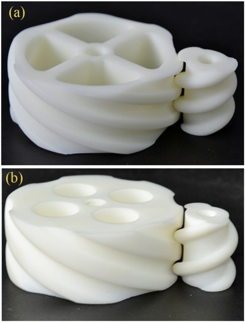
Photographs of nonrelative sliding gears for parallel axes transmission with (a) a uniform motion of meshing points and (b) a uniformly accelerated motion of meshing points.
Then, the transmission performance of two pairs of nonrelative sliding gears was tested on a precision four-dimensional (4D) motion table, as shown in Figure 10. The driving gear was driven by a DC micromotor, and the driven gear was rotated by the meshing between the concave–convex circular arc profiles.

Photographs of kinematics performance test for (a) a uniform motion of meshing points and (b) a uniformly accelerated motion of meshing points.
The sampling frequency was set to 5 Hz, and the constant rotation speed of DC micromotor was sat

Comparison of gear ratios.
Three main factors caused the error of instantaneous transmission ratio for the two types of gear pairs. The first factor was manufacturing error. The samples of two pair of gears were both fabricated via the RP technology. The accuracy of manufacturing was lower than that of numerical control (NC) machining. The different helicoids of experiment-a and experiment-b had different manufacturing errors. In both tests, the theoretical values of
Compared with the results of experiment-a, the relative error, standard deviation, and maximum variation of experiment-b slightly increased. The tooth surfaces of samples of experiment-a were equal-pitch helicoids. However, the tooth surfaces of samples of experiment-b were varying-pitch helicoids, and the form and manufacturing errors were larger than that of experiment-a. Both the instantaneous gear ratios fluctuated like a periodic sine wave. Despite the apparent errors, the fabricated test gear samples designed by the meshing line function-oriented method achieved a continuous gearing transmission for parallel axes.
Analysis of two types of meshing line motion functions for nonrelative sliding meshing for parallel axes transmission
The advantages of gear mechanisms with a uniform motion of meshing points are that they have the same axial pitch and movement speed of meshing points. This is easy for the design, manufacturing, and precision measurement of nonrelative sliding gears with a uniform motion of meshing points. Besides, both the contact curves present on the driving and driven gears are equal-pitch helixes, and the helix angles remain constant. All the meshing points are located at the tangent line of two cylindrical axodes, and the pressure angle remains constant. Therefore, the load force maintains the same magnitude and direction. Both the bending and contact stresses are mainly constant values in one stress cycle, ignoring the beginning and exit of one tooth meshing. This is good for maintaining the stability of gear transmission.
Regarding the gear mechanisms with a uniformly accelerated motion of meshing points, the axial pitch remains constant, and the helix angle of contact curves on the gears changes all the time. Therefore, the magnitude and direction of load force change along with the rotation of gears. The bending and contact stresses have periodic variation. This is not good for maintaining the stability of gear transmission. Moreover, this type of gear mechanisms with a uniformly accelerated motion of meshing points is difficult to design, manufacture, and measure, because the tooth profiles are not equal-pitch cylindrical helicoids. However, this type of gear mechanisms with a uniformly accelerated motion of meshing points can be used for special situations such as rapid tooth meshing in and out according to the meshing line active design method.
Generally, the type of gear mechanisms with a uniform motion of meshing points is better than that of gear mechanisms with a uniformly accelerated motion of meshing points to achieve a nonrelative sliding meshing for parallel axes transmission.
Comparative tooth contact analysis between nonrelative sliding gears with a uniform motion of meshing points and involute gears
Contact strength is one of the essential indexes for gear mechanism. The results of tooth contact analysis between the nonrelative sliding gears with a uniform motion of meshing points and involute gears were compared. The equation for theoretical contact stress calculation has not been deduced. However, the contact stress of one pair of nonrelative sliding gears with a uniform motion of meshing points was simulated using ANSYS Workbench 15.0 software. The material of driving and driven gears was set as steel with a modulus of elasticity

Simulation of a pair of nonrelative sliding gears with a uniform motion of meshing points.
Then, two pairs of involute gears (one was made of involute spur gears; another was made of involute helical gears) were designed with the same center distance and gear ratio. The geometrical parameters of involute gears are shown in Tables 2 and 3; they were calculated as reported in Wen. 22 The material modulus of elasticity and Poisson’s ratio of two pairs of gears are the same as shown in the above paragraph.
Geometrical parameters of involute spur gears.

Geometrical parameters of involute helical gears.

The input torque was

According to Wen,
22
K is the loading coefficient,
A comparison of calculated values of contact stresses shows that a pair of nonrelative sliding gears with a uniform motion of meshing points has the lowest contact stress. The contact strength can be significantly improved using the design method proposed in this article.
Conclusion
A new design method of nonrelative sliding gear mechanism for parallel axes transmission is presented. The design principle of meshing line function-oriented design was creatively proposed for the gear mechanism design. The motion governing the movement of meshing points along the meshing line can be expressed as a polynomial expression. The contact curves of driving and driven gears were obtained by the coordinate transformation of function-oriented designed meshing line equations. Then, the driving and driven tooth surfaces were obtained from the helical motion of plane generatrix curves along the calculated contact curves. Numerical examples of the two types of meshing line motion functions were deduced, and prototype samples were fabricated to experimentally validate the kinematic performance of the new design method of meshing line function-oriented design.
This meshing line function-oriented design method avoided the complex solution of meshing equations, thus simplifying the design process. The meshing line equations of motion and tooth surfaces can be flexibly designed to achieve a nonrelative sliding meshing for parallel axes transmission. However, the meshing characteristics, design criteria, parameter optimization, and precision manufacturing technology should be studied before the industrial applications of the method.
Footnotes
Appendix
Acknowledgements
The authors thank the editor and the reviewers for their helpful comments and suggestions.
Handling Editor: Yangmin Li
Declaration of conflicting interests
The author(s) declared no potential conflicts of interest with respect to the research, authorship, and/or publication of this article.
Funding
The author(s) disclosed receipt of the following financial support for the research, authorship, and/or publication of this article: This work was supported by the Natural Science Foundation of Hubei Province, China (No. 2016CFB280), The Fundamental Research Founds for National University, China University of Geosciences (Wuhan) (No. CUGL140823), The National Science-technology Support Plan Projects (No. 2015BAF32B03-06), and The Experimental Technology Research Project of China University of Geosciences (Wuhan) (No. SJ2015-18).