
Abstract
Based on the space curve meshing equation, in this article, a geometry design of a novel circular arc helical gear mechanism with pure rolling for parallel transmission was presented. Different from conventional circular arc gears, the meshing points of circular arc helical gears were limited at the instantaneous centre of rotation. The parameter equations describing the contact curves for both the driving gear and the driven gear were deduced from the space curve meshing equation, and parameter equations of the concave–convex circular arc profiles were established both for internal meshing and external meshing. Furthermore, a formula for the contact ratio was presented, and the impact factors influencing the contact ratio were discussed. Then, the parameter design was presented for the geometry parameters of tooth profiles, such as normal pitch, tooth height and tooth thickness. Using the deduced equations, several numerical examples were then considered, and prototype samples were produced to experimentally validate the contact ratio equation and the theoretical kinematic performance. The circular arc helical gear mechanism investigated in this study showed a high gear transmission performance such as a pure rolling meshing, a high contact ratio and a large comprehensive strength, when considering engineering applications.
Introduction
The meshing of conventional gears is usually based on the principle of conjugate surface meshing.1–3 The basic kinematic relations proposed by Litvin and Fuentes 4 relate to the velocities of the contact point to the contact normal for a pair of gears that are in mesh. Involute gears, parabolic gears, 5 cycloidal gears 6 and circular arc gears, 7 which are widely used in industry applications, are designed and manufactured strictly according to this conventional principle of conjugated surface meshing. However, curvature interference and undercut strongly limit the design of tooth profiles and number of teeth, especially in conventional gear designs, for example, involute gears and cycloidal gears.2,3 The relative sliding between the driving and driven tooth surfaces of conventional conjugated surface meshing gears is the main factor which causes the transmission failure of wear, scuffling and plastic deformation, especially in worm gears.2,3
The space curve meshing equations have been established by Chen et al.8,9 and Chen 10 who thereby established the meshing theory of conjugated space curves. Then, Chen and colleagues11–13 developed the conjugate curves theory for arbitrary contact directions. Utilising the space curve meshing equations, line gears have recently been extensively studied for microelectromechanical system (MEMS), including space curve meshing wheels (SCMWs)14–17 used in case of intersecting axes with an arbitrary intersection angle and space curve meshing skew gear mechanism (SCMSGM) 18 used in case of skew axes with an arbitrary skew angle.
However, the driving and driven tines of these line gears can both be regarded as cantilever beams, which cannot absorb enough loading for conventional mechanical applications. If the loading is for conventional power transmission, transmission failure occurs in the form of elastic deformation or even a fracture of the tines of line gears. Thus, the line gears introduced above are mainly suitable for micromechanical systems with a low power, 10 and this restricts the applicability of space curve meshing theory.
By adopting the concave–convex meshing form of arc gears, which offers the advantage of a large synthetic curvature radius, a geometry design method for the design of a novel pure rolling circular arc helical gear mechanism (CAHGM)19,20 with concave–convex meshing is presented in this article for parallel transmission applications. Then, a formula for calculating the contact ratio for CAHGM is given. After the analyses of contact ratio, the parameter design for CAHGM is presented. Furthermore, the experiments were performed to study the kinematic performance of the fabricated CAHGM prototypes to validate the theoretical transmission model established for the CAHGM.
Geometry design of CAHGM for parallel axes transmission
Space curve meshing coordinate transformation matrix for parallel transmission
There are two ways for achieving parallel transmission when designing a pair of CAHGM, that is, external gearing and internal gearing. Figure 1(a) and (b) shows the coordinate system for external gearing and internal gearing, respectively.

The space curve meshing coordinate systems for parallel-axis transmission: (a) θ = 180° and (b) θ = 0°.
The coordinate transformation matrix

According to the space curve meshing theory, for a pair of conjugated space curves that are in mesh, the relative velocity at the contact point and the principal normal vector at the contact point must therefore satisfy the following space curve meshing equation 9

For the following calculations, a cylindrical helix was chosen as the driving contact curve and the meshing point is denoted as P.

where
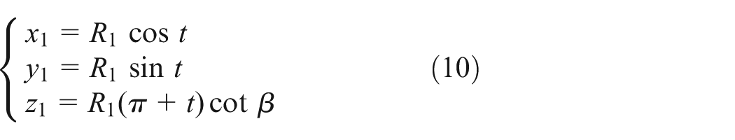
For a right-handed cylindrical helix as an example of a driving contact curve, the right-handed driving contact curve in


where
The unit principal normal vector of the driving contact curve can be represented by 21

The relative velocity vector at the meshing point is then given by 9

When

Equation (7) indicates the one-to-one relationship between
Therefore, the rotation angle of the driving gear for the rotation of a driving tooth from entering the meshing to withdrawing from the meshing is

Considering equations (1), (3), (4) and (7), the driven contact curve in


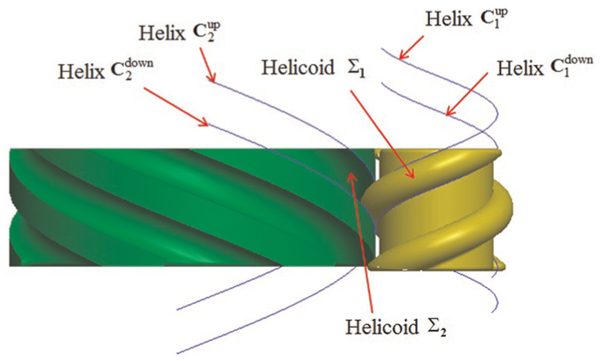
According to equation (9), if the driving contact curve can be described as a cylindrical helix, the driven contact curve is also a cylindrical helix, and the magnitudes of both helix angles are the same. For external gearing, the helix angle of the driven helix is the opposite of the helix angle of the driving helix. For internal gearing, the helix angles are identical. In Figure 2, two conjugated cylindrical helixes are shown for parallel transmission and an external gearing mechanism.

Illustration of two conjugated cylindrical helixes of an external gearing mechanism for parallel-axis transmission.
For parallel transmission, there are two possible designs for the meshing between the two cylindrical helixes: a right-handed cylindrical helix for the driving curve and a left-handed cylindrical helix for the driven curve; or a left-handed cylindrical helix for the driving curve and a right-handed cylindrical helix for the driven curve. Point contact meshing occurs in both cases, and the contact points form a straight line
There are three aspects of differences between the proposed circular arc helix gears and the existing circular arc gears. First, the most difference between the proposed circular arc helix gears and the existing circular arc gears is that the meshing contact points of CAHGM are the instantaneous centre of rotation, but meshing contact points of the existing circular arc gears are not the instantaneous centre of rotation. Second, the relative velocity of CAHGM theoretically is 0, but the relative velocity of the existing circular arc gears is not equal to 0, and the relative sliding still exists. Third, CAHGM has large bending strength because they could be designed with low tooth number and have large tooth thickness. But the existing circular arc gears have low bending strength for its special tooth profile design.
According to equations (4) and (9), for parallel transmission, the meshing condition for two cylindrical helixes is as follows: the helix angles of the two cylindrical helixes have the same magnitude, with opposite spiral handedness for an external gearing mechanism and the same spiral handedness for an internal gearing mechanism. The circular arc profiles for a concave–convex meshing can then be constructed based on a helical motion of two conjugated cylindrical helixes.
Equations of concave–convex meshing circular arc profiles
For

Models used to describe the generatrix circular, the helix and the circular helicoid for both (a) the driving gear and (b) the driven gear.
Meshing between the two circle helicoids.
According to equation (4) and using the coordinate system
and the parameter equations for

where
For a right-handed helical motion in the coordinate system

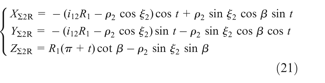
According to equation (9), using the coordinate system

and the parameter equations for

where
For a left-handed helical motion in the coordinate system

Equations (12) and (15) describe the circular arc profile for a concave–convex meshing. Switching the lateral rotation of the two circular helicoids
As explained in section ‘Space curve meshing coordinate transformation matrix for parallel transmission’, if the driving contact curve is a left-handed cylindrical helix, the driven contact curve is a right-handed cylindrical helix. Next, the parameter equations for the circular arc profiles in case of a concave–convex meshing are deduced.
For the coordinate system

and the parameter equations

For a left-handed helical motion in the coordinate system

and the parameter equations for the right-handed helix

and the parameter equations for

For a left-handed helical motion in the coordinate system
There are two possibilities for realising the circular arc profiles for a concave–convex meshing. The first design option is shown in Figure 5(a), where the concave circular arc profile is on the pinion and the convex circular arc profile is on the large gear. The second design option is illustrated in Figure 5(b), where the convex circular arc profile is on the pinion and the concave circular arc profile is on the large gear. The overall weight of the first system is larger than the overall weight of the second system. Therefore, in this study, the second design option was chosen to achieve a concave–convex meshing due to its more lightweight design.
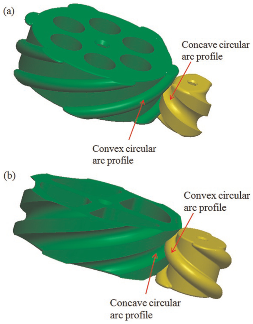
Illustration of the two different ways to realise a concave–convex meshing of circular arc profiles: (a) concave circular arc profile on the pinion and (b) convex circular arc profile on the pinion.
Calculation of sliding ratios for CAHGM
CAHGM belongs to the meshing theory of space curve meshing, and the meshing between the two circular helicoids can be described as the meshing between the two conjugated cylindrical helixes on the two circular helicoids. Consider the two gears are rigid model, and there is no deformation between the two surfaces. According to Wu, 3 the sliding ratios of conjugated surfaces are expressed by

Section ‘Space curve meshing coordinate transformation matrix for parallel transmission’ indicates that point contact meshing occurs with CAHGM, and the contact points are the instantaneous centres of rotation at any meshing time. Meanwhile, equations (4), (6), (7) and (9) yields

So

That is to say, the sliding ratios of conjugated surfaces of CAHGM theoretically are 0.
Design formula for tuning the contact ratio equation and impact factor analysis
Design formula for tuning the contact ratio
The contact ratio of classical gears was defined in Budynas et al.,
22
but its definition was complex in form and in calculation. The contact ratio for SCMW for vertical transmission and arbitrary intersecting axes has been studied previously, and the contact ratio

Substituting

Equation (23) indicates that if helix angle
Impact factor analysis
Contact ratio design based on the cylindrical helix parameter t
Only an external meshing was considered. For

Results of the kinematic simulation with the same tooth number: (a)
The results indicate that when the tooth number is fixed, the contact ratio increases with the parameter value range of cylindrical helix. The clearance between the contact curves remains constant, but the tooth width gradually increases, as shown in Figure 6. When
Contact ratio design based on tooth number z
Only external meshing was considered. For

Results of the kinematic simulation with the same parameter value range of cylindrical helix: (a)
The results indicate that when the parameter value range of cylindrical helix is fixed, the contact ratio increases with the tooth number. The tooth width remains constant, but the clearance between the contact curves gradually decreases, as shown in Figure 7. When
Design based on the minimum tooth number
For a contact ratio equal to or larger than 1, the allowable minimum tooth number
According to equation (25),

Results of the kinematic simulation with the same contact ratio: (a)
The results showed that the minimum tooth number of the CAHGM which can ensure a contact ratio larger than one is one, when the value range of the parameter
Parameter design for CAHGM
A meshing sketch for a pair of CAHGM is shown in Figure 9(a). Exactly, the contact point P may lie everywhere from Point A to Point B on the concave arc curve. When it lies at Point A, it makes edge contact. When it lies at Point B, it is hard to transmit power. So, in this article, the contact point is set be on the middle radii distance of Point A to Point B, as shown in Figure 9(b). And Point A should be replaced by a transition fillet with fillet radius

Assembly of a pair of CAHGM: (a) cutaway view and (b) partial enlargement view.
Figure 10 illustrates evolution of the two cylindrical surfaces which are passing through the driving cylindrical helix and the driven cylindrical helix, respectively. The normal module

Schematic illustration of the pitch circle evolution of the two cylindrical surfaces: (a) the driving gear and (b) the driven gear.
Basic design parameters used to model the CAHGM for parallel transmission.

CAHGM: circular arc helical gear mechanism.
The other parameters required to model a pair of CAHGM for parallel transmission were then calculated using the basic design parameters. And they are listed in Table 2.
Additional parameters for modelling a pair of CAHGM for parallel transmission.

CAHGM: circular arc helical gear mechanism.
According to Table 2, if the pitch diameters are the same, the tooth number of CAHGM is less than that of spur gears, helical gears and circular arc gears, and the normal module of CAHGM is much larger than that of spur gears, helical gears and circular arc gears. So the bending stress of CAHGM is the least one in the four parallel-axis gearing mechanisms under the same loads. Meanwhile, the concave–convex tooth profile of CAHGM has large synthetic curvature radius which could greatly reduce the contacting stress like the circular arc gears. That is to say, CAHGM has higher bending strength and contacting strength than the other parallel-axis gearing mechanism. This merit is beneficial for the engineering application of CAHGM.
Kinematic performance tests
Fabrication of the testing samples
A pair of CAHGM was designed with the following parameters:
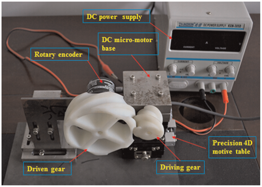
Photograph showing the setup used for the kinematic performance tests.
Experimental setup and kinematic performance tests
A precision four-dimensional (4D) motion table was used for fixing the CAHGM, as shown in Figure 11. In the experiments,
Experimental results and analysis
During the testing, the sampling frequency was set to 5 Hz, and the constant rotational speed of the DC micro-motor was 288°/s at a voltage of 6 V. The instantaneous gear ratios obtained through

Comparison of the instantaneous gear ratio and the theoretical gear ratio.
The relative errors are mainly caused by manufacturing errors, assembly errors and measurement errors. Despite these errors, the fabricated CAHGM was capable of achieving a continuous parallel-axis transmission with a stabile gear ratio.
Conclusion
The geometry design of the CAHGM used for parallel axes transmission with concave–convex circular arc profile is presented in this article. The meshing conditions of a pair of CAHGM for parallel transmission were revealed, and the effect of different impact factors on the contact ratio is studied based on a detailed theoretical analysis and numerical simulations. The parameter design for CAHGM is presented, and the experiment for kinematics performance of prototypes is carried out. The results indicate that the CAHGM can transmit rotation between parallel axes continuously. Based on the above studies, the following conclusions can be drawn:
The contact meshing between CAHGM for parallel axes is pure rolling, which avoids the relative sliding of two surfaces.
The matching way of concave to convex circular arc profiles has large synthetic curvature radius. CAHGM has higher bending strength and contact strength than the other parallel-axis gearing mechanism.
The contact ratio of CAHGM could be designed flexibly by changing value scope of parameter
Contact ratio
Before the proposed CAHGM for parallel transmission can be widely used in industry for parallel axes, can be conveniently manufactured and deployed, much work remains to be done. Our future researches should therefore focus on the optimal design, failure criteria, precision manufacturing methods and so on.
Footnotes
Appendix 1
Acknowledgements
The authors would like to thank the editor and the reviewers for their helpful comments and suggestions.
Academic Editor: Yangmin Li
Declaration of conflicting interests
The author(s) declared no potential conflicts of interest with respect to the research, authorship, and/or publication of this article.
Funding
The author(s) disclosed receipt of the following financial support for the research, authorship, and/or publication of this article: This work was supported by the Natural Science Foundation of Hubei Province, China (no. 2016CFB280), the Fundamental Research Funds for the Central Universities, China University of Geosciences (Wuhan; no. CUGL140823) and the Experimental Technology Research Project of the China University of Geosciences (Wuhan; no. SJ2015-13).