
Abstract
The fully tempered vacuum glazing, consisting of two fully tempered glass plates detached through a limited vacuum medium (below 0.01 Pa), is presented. The heat transfer through fully tempered vacuum glazing is complex, including heat conduction, thermal radiation, and convection. To analyze heat conduction through a stainless steel support ball, the thermal resistance of the support ball is established based on Hertzian contact model. And the total thermal resistance of the unit cell with one support ball is defined. The three-dimensional finite element model for a center unit cell of fully tempered vacuum glazing is simulated to validate the result of the total thermal resistance. The simulation transmission U-values are 0.26 W/m2 K. Meanwhile, the simulation transmission U-values of entire fully tempered vacuum glazing are 0.84 W/m2 K without frame insulation.
Keywords
Introduction
International Energy Agency (IEA) reveals approximately 40% of global energy consumption coming from buildings. 1 Supplying vision, ventilation, and daylighting, windows are necessary components of healthy buildings. 2 However, compared with other components of architecture, U-values of windows are especially higher. Cuce and Cuce 1 indicate that the U-values of windows are up to 2.00 W/m2 K while the U-values of ceiling, ground, and outer walls are about 0.16, 0.25, and 0.30 W/m2 K separately for one typical building. What is more, approximate 60% of the overall energies loss of one building may be relevant to its windows. Hence, windows have a great potential to reduce heat transfer and provide huge energy savings.
As remarkably energy costs increasing, many countries, including developed countries and developing countries, pay more and more attention to energy efficiency of windows. For instance, the U-values of new windows in Norway and the United Kingdom are restricted to be within the limits of 1.20–1.40 W/m2 K.3,4 Buildings in Germany are required to attain energy demand for heating below 15 kWh/m2 year, corresponding to the U-values of windows below 0.8 W/m2 K. 5 Similarly, in China, the most excellent performance of vacuum glazing should meet the basic requirements that the U-values are equal to or less than 1.0 W/m2 K. Multiple attempts have been made worldwide to reduce the energy consumed by windows. Eames 6 believes that vacuum glazing, as an advanced technology among low heat loss glazing systems, has been developed to reduce energy losses caused by windows. Jelle et al. 3 consider that the development of vacuum glazing and aerogel glazing is remarkable advance in the area of energy losses fenestration products with the large potential to minimize heat transfer. The U-values of aerogel glazing may be the lowest which can be below 0.1 W/m2 K, whereas ulteriorly research needs to be done to enhance the visible transmittance of the glass systems with aerogel.7,8
The thinking of vacuum glazing was initially put forward by Zoller 9 in 1913. It was not until 1989 that the vacuum glass fabricating had been reported for the first time; Robinson and Collins utilized solder glass plate with a fusing point of 450°C to solve the problem in edge seal. 10 However, such high sealing temperature will cause failure of tempered glazing and much soft low-emissivity coating, because both of them will degrade at high temperature of about 450°C. Due to the very low intensity of regular float glass plates and the serious pressure concentration caused by support column, vacuum glazing shows the characteristic of low intensity and is more prone to be broken than a traditional glass.11,12 Hyde et al. 13 found that edge seal of vacuum glazing can be achieved at the temperature of less than 200°C if an indium or indium-based alloy was used. Which also made it is possible to use much supple low-emissivity coatings and tempered glass.
As a breakthrough of vacuum glazing technology, fully tempered vacuum glazing (FTVG) is proposed in this article. The FTVG, as shown in Figure 1, consists of two plates of fully tempered glass separated by a limited vacuum medium. A high-performance low-emissivity coating is on one fully tempered glazing surface within the vacuum zone can reduce effectively radiant heat transfer. To reduce the heat transfer caused by support pillars as much as possible, the stainless steel pillar array is replaced by a stainless steel ball array in this article. Compared with pillars, balls can minimize the touch area between glazing plates and spacers. The heat transfer behavior in the FTVG is complex, including heat conduction, thermal radiation, and convection. In order to accurately predict heat transfer behavior and minimize the heat loss caused by the FTVG, mathematical models of heat transfer through the FTVG are established and simulation of coupled conduction–radiation is performed in this study.

3D schematic diagram of FTVG.
Characteristics of FTVG components
Figure 2 shows the structural details of FTVG, which comprised two 4- or 5-mm-thick fully tempered glass panels, and one of the glass panels is the fully tempered low-emissivity glass. The low-emissivity coating can effectively reduce thermal radiation between the parallel glazing panels. The edge sealing of FTVG can be achieved at low temperature of 300°C. Through the vacuum implementation point, air will be extracted in order to keep a vacuum space between the two glass sheets.

Structural details of FTVG.
Fully tempered glass sheets
Float glass or annealed glass, often referred to as ordinary glass, has not enough strength because of their surface flaws and tensile stress which may easily lead to their failure. 14 Ordinary float glass is crisp and may be destructed into sharp and dangerous fragments due to outer impact, which may give rise to very serious damage. Safety glazing is fully tempered glass that meets the requirements of the safety glazing standard CPSC 16 CFR 1201 or ANSIZ97.1. 15 Compared to ordinary float glass, safety glazing significantly reduces the likelihood of severe cutting or piercing injuries when it is broken and fractures into comparatively small pieces.
Tempered glass could be obtained from float glass through an extra process named hardening, in which the glass is taken into a furnace to heat to its transition temperature, usually above 600°C, and it then rapidly cooled with forced airflow. Therefore, the outer surfaces of the glazing are forced to shrink and develop residual compressive stresses while the interior zone of the glass develops compensating tensile stresses. It is this surface compress stress that makes the tempered glass increased strength. The larger the compressive pressure is, the tinier the glazing particles would be when it is broken. With respect to fully tempered glass, the surfaces compressive stresses should be more than 100 MPa. Fully tempered glass has more than four times the strength of regular float glass of the same size and thickness. 16 The high-quality tempered glass is related to the temperature of tempering process, to get command of temperature of the tempering stove is very crucial technology in the tempered glass fabricating process. Some product defects could occur if the temperature control is inadequate, such as insufficient glass hardness.
Before tempering process, the float glass must be cut to the size what we need as well as polishing the edges and drilling holes, because the tempered glass cannot be re-worked. After the tempering process, heat soak testing at temperatures of 290 ± 10°C should be taken to avoid a so-called spontaneous breakage of the tempered glass. Therefore, the fully tempered glass sheets are chosen in the FTVG to make sure the safety of windows.
Support stainless steel balls choice
Due to barometric pressure bearing on the outer side surface of glazing substrates, the compressive strength of the chosen spacers should be at least 1 GPa. Ceramics, stainless steel, and Inconel 718 are appropriate spacer material. 17 In addition, the permissible tensile strength of the glazing substrates is approximately 8 MPa. 18 So the suitable spacer array should be designed to ensure that the tolerable mechanical tensile stress of glass substrates should be below 4 MPa. 19 Rings and pillars are applied as the support spacers all the time, but their shortcomings are noticeable:
To produce the mini-rings and mini-pillars is very expensive.
To complete the stacking process of spacers is too hard.
Due to the large contact area between glass sheets and pillars, lots of heat loss happened through pillars or rings.
In order to overcome above problems and reduce the heat loss caused by spacers, a novel 0.5 mm stainless steel balls is proposed as support spacers in this article. Furthermore, these 0.5 mm stainless steel ball array is placed at 60 mm in a equilateral triangle mode to replace those cylindrical support column array spaced at 25 mm in a routine foursquare mode.
Low-emissivity coatings
As we all know, ultraviolet light, with a wavelength of 0.10–0.37 μm, may lead to interior materials of buildings such as fabrics and wall coverings to fade. Infrared light (2 μm and above), with longer wavelengths than visible light (0.38–0.78) μm, 19 is transmitted as heat energy into buildings. Low-emissivity coatings effectively reduce the amount of ultraviolet light and infrared light which can pass through glass, while still maintaining high levels of visible light transmission. Therefore, low-emissivity coatings have been used on internal surfaces within the vacuum zone of FTVG to reduce radiant heat transfer.
Low-emissivity coatings contain two categories: one of them is tough and the other one is soft. Through pyrolytic deposited metal oxides, hard coatings are fabricated on the process of the float line production, and this method is called on-line coatings. Soft coatings are off-line coatings, and they are often obtained by magnetron sputtering. The emittance of soft coatings is lower than that of hard coatings.
Through decrease the emissivity of low-emissivity coatings from 0.18 to 0.03, the U-values in the glazing area center were reduced from 0.41 to 0.22 W/m2 K, and the lowest emittance attained until now is 0.02. 20 Fang et al. 21 utilized the simulation and experimental results to prove that the improvement of thermal transmittance is limited when two low-emissivity coatings are applied in the vacuum glazing; an excellent performance vacuum glazing is obtained using a single high-performance low-emissivity coatings. What is more, the cost of two low-emissivity coatings is much more expensive than that a single high-performance low-emissivity coatings.
Edge seal
Edge seal is one of the important techniques of manufacturing the FTVG; it not only serves to keep the hermeticity of vacuum cavity, but also to provide mechanical strength for two glass sheets. A variety of different edge seal techniques have been studied: laser-welding, 22 low-temperature glass soldering to temperatures around 500°C, 23 an indium-based seal augmented with a resin, 24 and soldering metal foils in combination with layer of adhesives.25,26
A novel continuous method for glazing evacuate and seal had been developed with low temperature which is lower than thermal tolerance of low-emissivity coating and tempered glazing is allowed in this situation. The low-temperature glass has a coefficient of thermal dilation that may well match that of the glass substrates of FTVG. However, since the 500°C sealing temperature can result in failure of tempered glass, the low-temperature glass cannot be used. The indium-based seal augmented with a resin may replace the low-temperature glass as a flexible edge seal which cannot cause internal mechanical stresses, and the material indium had been used in standard glass evacuated and edge seal at temperatures of 200°C. But the scarcity and cost of indium alloy prevent its mass production.
Mathematical model for the FTVG
Figure 3 shows the schematic diagram of FTVG intersecting surface and the heat-transmit through FTVG. The heat transfer includes heat conduction, thermal radiation, and convection. Mathematical models of heat transfer through the FTVG are established to accurately solve heat transfer equations. And the finite element method (FEM) simulations of coupled conduction–radiation are performed to verify the mathematical models.

Schematic diagram of FTVG intersecting surface and the heat conduction through FTVG.
The heat transfer through the FTVG in eight ways:
Heat and radiant flow from the warm flank to the glass sheet external surface 1;
Conduction through the glass sheet from external surface 1 to internal surface 2;
Heat radiant flow between interior surfaces 2 and 3;
Heat flux through the supporting ball array;
Heat flux through the marginal seal;
Heat flux through glazing plate from internal surface 3 to external surface 4;
Heat flux and convection from the cold side to the glass sheet external surface 4;
Heat flux through the remnant gas in the vacuum zone (not shown in figure).
Heat transfer through a stainless steel ball
Stainless steel balls are essential in the FTVG to keep the distance of two parallel glass substrates and to balance the barometric pressure on the glazing plates. Since support balls are in contact with the internal surfaces of the two substrates and their material is 304 stainless steel which with good thermal conduction, Qb is used to characterize the heat flow of a miniature support ball. Qb is given by

where Rg,b is a support ball thermal resistance which is related with a tiny round contact between two insular half-boundless plates of material.17,27Ts2 and Ts3 are the average temperature of the two internal surfaces 2 and 3, respectively. Thermal resistance can be obtained from the classical expression as

which kg is thermal conductibility of the glass; a is contact radius of support ball and fully tempered glass sheets. Based on Hertzian contact model, α is given by
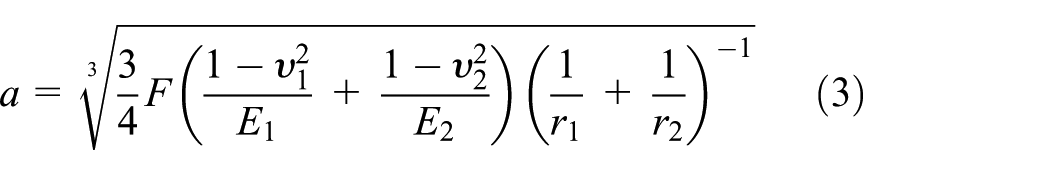
where F is the Hertzian contact force. 28 r1 is the radius of miniature support ball. r2 is the radius of semi-infinite glass sheets. Correspondingly, ν1 is Poisson’s ratio of the support ball; ν2 is Poisson’s ratio of the fully tempered glass

Substituting equation (4) into equation (3), contact radius equation (3) can be calculated as
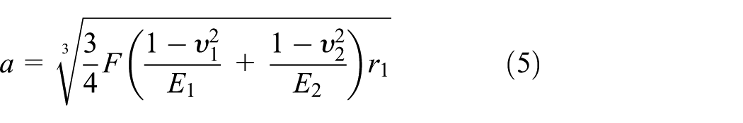
where E1 and E2 are Young’s modulus of support ball and fully tempered glass sheets, respectively.
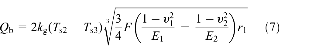
Once the contact radius of the miniature support ball and fully tempered glass sheets is obtained by solving equation (5), along with the classical expression in equation (2), the heat flux Qb through a uniparted support ball in equation (1) can be calculated as

The thermal resistance of a support ball can also be obtained according to equation (5)
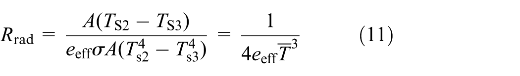
Radiant flux between two interior surfaces
Radiation is transmission of heat flux energy through space or a material medium. A low-emissivity coating of high transmission allows daylight from the sun to pass but reduces the amount of the long wavelength infrared heat that can escape through the window. The radiant heat flux Qrad between two parallel interior surfaces of the glass plates could be written as 29

where σ is the Stefan–Boltzmann fixed value of 5.67 × 10⁻⁸ W m−2 K−4; eeff is effective emittance of fully tempered glass panels; A is the region in two paralleled internal surfaces; Ts2 and Ts3 are the average temperature of the two internal surfaces 2 and 3, respectively.
Only if the radiation reflectance is independent at the wavelength and angular of incident radiant flux, the effective emissivity eeff can be given by
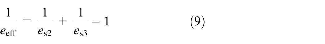
where es2 and es3 are the hemispherical emissivity of the two interior surfaces 2 and 3 at the appointed temperatures, respectively.
The thermal resistance of radiation between glass surface 2 and surface 3 within the vacuum gaps is defined according to equation (8)

According to the radiative heat flow Qrad, the thermal resistance of radiation can be described as
Low-emissivity can effectively reduce radiative heat transfer.
Heat conduction of residual gas
Since the vacuum pressure of FTVG is lower than 0.01 Pa, the thermal conductivity of the gas between the glass panels can be written as 30

which γ is the appointed heat rate of the gases, M is the molar mass of the gas, T is an average temperature between two internal surfaces of the glass substrates, NA is Avogadro’s number, k is Boltzmann’s fixed value, and α is the combined accommodation coefficient.
α can be obtained according to equation (13)
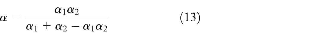
where α1 and α2 are the accommodating coefficients of the gas mole with the two internal surfaces. 30 It has been shown that the thermal convection and conduction of the gas can be negligible when vacuum pressure is inferior to 0.1 Pa. 20
Heat conductivity of the glazing substrates
The thermal resistance of each glass sheet can be calculated as

where kg is the thermal conductivity of the glass and t is the thickness of glass plate.
Supposed the temperature of the outside surface is uniform, the external surfaces 1 and 4 thermal resistance of FTVG is determined by


where hi and hj are the heat flux coefficient of warm side and cold side, respectively.
However, the temperature of outside surfaces of FTVG, strictly speaking, is not uniform because of the complex heat flux behavior between the ambient circumstance and glass surfaces, including gas conduction and convection as well as radiation.
Coupled conduction–radiation model
In order to accurately predict heat transfer behavior at the center of FTVG, the analytic model for calculating thermal resistance of a unit cell of FTVG is established. The center unit cell only contains one support ball and the thermal convection and conduction of the gas is negligible. The schematic representation is shown in Figure 4.

Thermal resistance network model through the center unit cell of FTVG.
At the center of FTVG, the total thermal resistance of the unit cell with one support ball is the given as follows
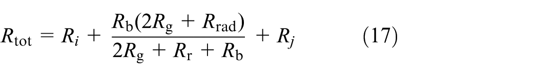
The total heat transfer coefficient (U-value) of the center unit cell is calculated according to equation (18)

3D finite element model
The formula (18) can be used to calculate the heat transfer coefficient of the FTVG center unit. However, the central unit calculates only the heat transfer caused by one miniature support ball. In fact, the vacuum glass consists of two parallel plates which is supported by many micro balls, these support balls are all made of 304 stainless steel. Selecting an appropriate supporting ball array (diameter and spacing) can not only effectively support two parallel glass plates to maintain a good vacuum, but also reduce the heat loss caused by the support balls. In order to minimize the heat loss caused by the micro-support ball spacing, this article attempts to deploy the support ball in a triangular manner. The heat transfer coefficient of the miniature support ball array can be calculated by multiplying the single support ball by the number of support balls per unit area

In equation (19), a is the contact radius between the support ball and the glass plate, and p is the distance between the micro-support balls.
The smaller the support ball diameter, the greater the spacing, the better the thermal conductivity of the vacuum glass. It must also be considered that the maximum stress generated by the contact between the glass plate and the miniature support ball must be less than the allowable compressive stress allowed by the glass
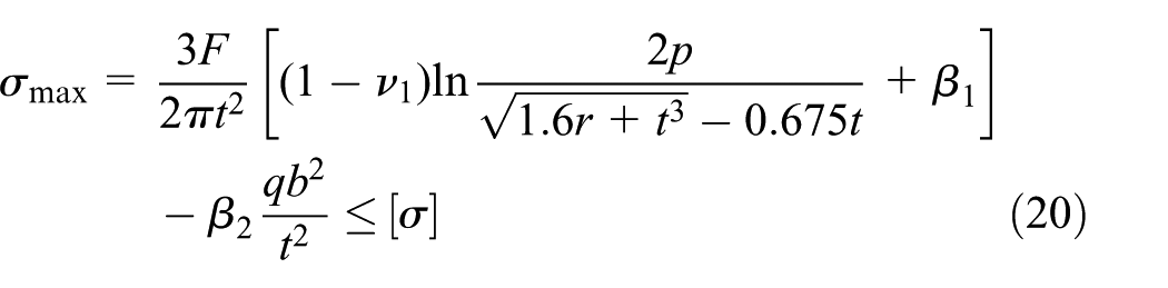
where
Under the influence of external atmospheric pressure, the interaction between the glass plate and the micro-support ball will cause tiny indentations in the glass plate—Hertz indentation. When the Hertz indentation expands Hertz taper crack, it means that the indentation has caused damage to the glass. In order to avoid unsafe factors such as the drop of the strength for glass caused by the Hertz taper crack, the minimum diameter of the support must be limited

In equation (21),
In this article, genetic algorithm is used to solve the problem of the optimal diameter and spacing of the support ball. The binary digits PRECI = 20 and the maximum iteration algebra MAXGEN = 80 are used to construct the fitness function (object function)

Take equations (20) and (21) as constraints for the fitness function. The genetic algorithm MATLAB running curve is shown in Figure 5.

Genetic algorithm running curve.
It should be noted that in equation (22), a is the contact radius between the support ball and the glass plate instead of the radius of the support ball. The radius r of the support ball can be acquired through experience. After genetic algorithm solving and experience conversion, the final result is obtained. As a result, when the radius of the supporting ball is 0.25 mm and the supporting ball pitch is 60 mm, the vacuum glass has a good heat insulating performance.
Many scholars choose square layout when the support is deployed, and the square layout increases the number of supports. This article adopts a triangular approach and uses the genetic algorithm to solve the optimal support ball diameter and spacing, effectively reducing the number of supports. And the insulation performance of vacuum glass is improved. The micro-support ball triangle placement structure is shown in Figure 6.

Micro-support ball triangle placement structure.
Results and discussion
To settle the problem of coupled heat-flow-radiation, there are many approaches exempli gratia the finite difference measure (FDM), 31 the FEM,32,33 the finite volume measure (FVM), 34 and the lattice Boltzmann measure (LBM).35,36 The FEM is one of the most widely used reliable numerical approach. 37 The FEM is an efficient numerical method for solving problems with complicated geometries, loadings, and material properties. And it has been shown that the thermal convection and conduction of the gas can be negligible when the vacuum pressure is inferior to 0.1 Pa. 20 Therefore, the FEM is utilized to predict the temperature distribution and the U-values of FTVG.
3D finite element modeling for a center unit cell of FTVG
In order to predict the thermal transmission at the center unit cell of FTVG (30 mm × 30 mm) with 0.5 mm support ball in the central, a 3D finite element model was established to simulate the heated capability. The central unit model is shown in Figure 7. Thickness of the center unit cell of FTVG was 8.5 mm. The emittance of the low-emissivity coating on the internal surfaces was 0.04. The simulation transmission U-values for the center unit cell of FTVG was predicted to be 0.26 W/m2 K under the boundary conditions of ISO standard 10077-1. 38 The parameters of the boundary conditions are summarized in Table 1. And the material heat transfer coefficients of FTVG in the finite element model are represented in Table 2.

Center unit model.
Marginal conditions.

Heat transfer coefficients on the components of FTVG.

The predicted 3D finite element model for a center unit cell of FTVG is presented in Figure 8, which reveals the temperature distribution for the center unit cell of FTVG due to vacuum space high thermal impedance. The support ball is one reason for the heat loss and the low-emissivity coating can minimize the heat loss are illustrated in Figure 8. So to decrease the number of support ball can reduce the heat loss of FTVG. The U-values (0.26 W/m2 K for the center unit cell of FTVG were concordant with the mathematical model calculated according to equation (18) with a 1.6% deviation.

Predicted 3D temperature distribution for a center unit cell of FTVG.
3D finite element model for one quarter of FTVG
Due to symmetry in vacuum glass, only one-fourth of FTVG had been simulated under the boundary conditions of ISO standard 10077-1. The simulated FTVG was 300 mm × 300 mm and consisted of two 4 mm thickness fully tempered glass sheets. The geometry model for one quarter of FTVG is shown in Figure 9. One of the glass surfaces inside the vacuum zone was covered with a high-performance low-emissivity coating with emissivity of 0.04. A 0.5 mm diameter support ball array, placed at 60 mm in an equilateral triangle mode, was used to ensure the distance of the two parallel glazing substrates and to balance the barometric pressure on the glass plates. The two glass plates were sealed with a 6 mm width band of tin alloy.
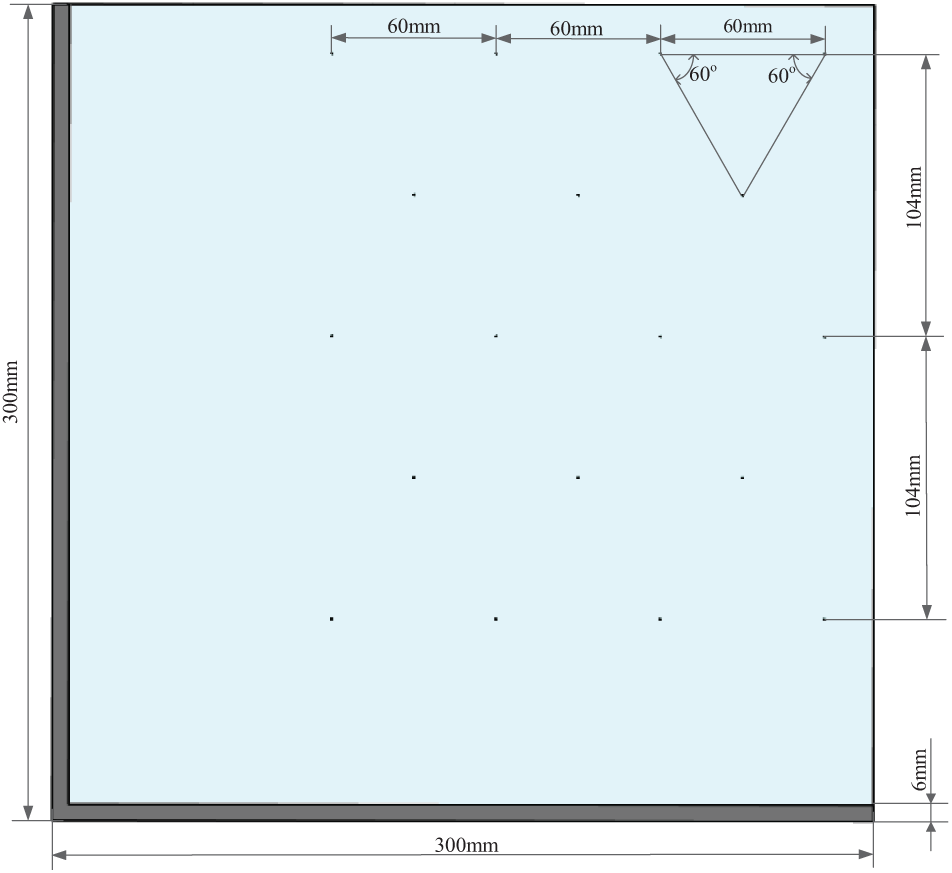
Geometry model for one quarter of FTVG.
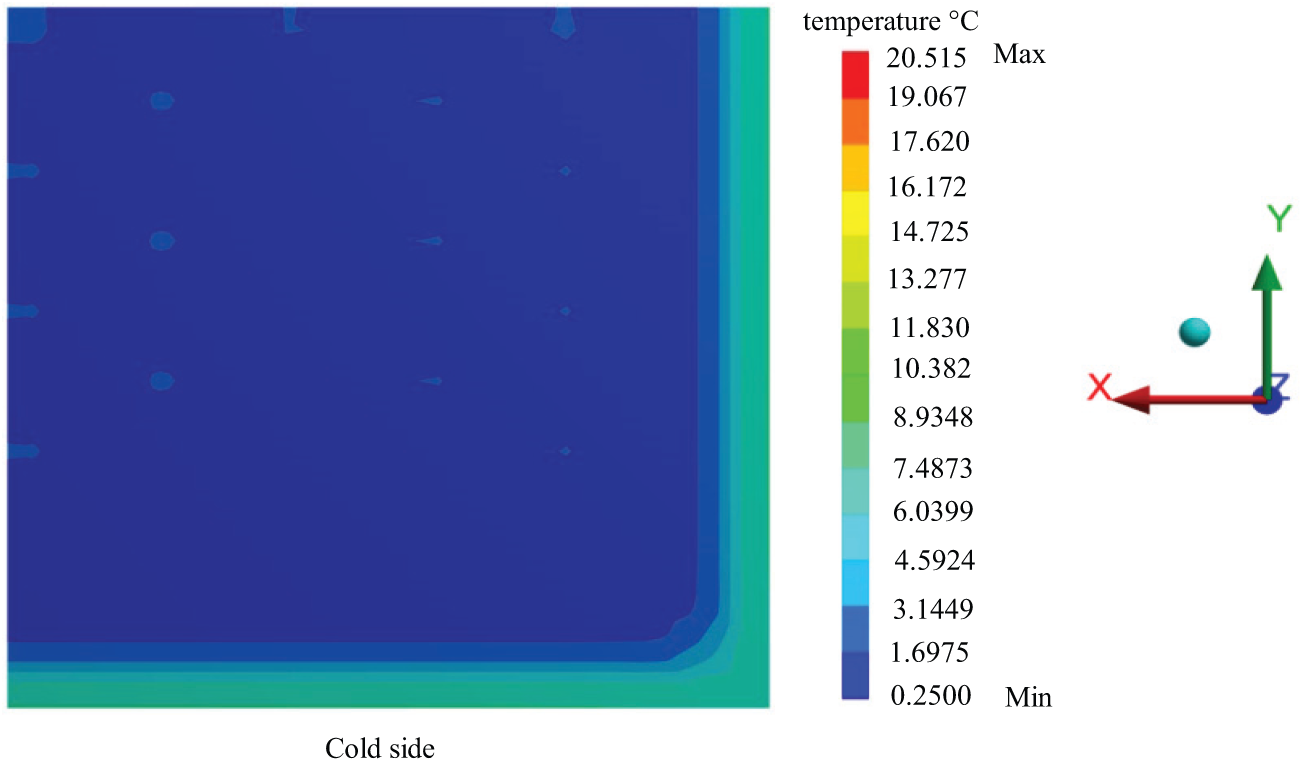
The 3D finite element model for one quarter of FTVG is presented in Figure 10 under the marginal conditions of ISO standard 10077-1. Figure 10 shows the temperature gradient across the two glass substrates due to the high thermal impedance of the vacuum space.

Predicted 3D temperature distribution for one quarter of FTVG.
Figures 11 and 12 show the temperature distribution on the warm surface and cold surface of FTVG caused by the edge seal, separately. The temperature of the cold surface of the glass is 1.69°C, while the temperature of the warm surface of the glass is 20.51°C. The temperature for the edge seal and the support ball is slightly different, temperature for edge seal is 10.38°C, and support ball is 16.17°C on warm side, respectively. The temperature for edge seal is 7.48°C and support ball is 4.59°C on cold side, respectively. It seems obviously that the edge seal and support balls are the reason for the temperature difference. The simulation transmission U-values of FTVG are 0.84 W/m2 K without frame insulation. The U-values of FTVG are three times bigger than that for the center unit cell of FTVG because of the good thermal conduction of edge seal.

Predicted 3D temperature distribution for one quarter of FTVG on the warm surface.
Predicted 3D temperature distribution for one quarter of FTVG on the cold surface.
Conclusion
A new kind of vacuum glazing—FTVG is proposed. The FTVG consists of two fully tempered glass substrates. The FTVG is safety glazing and can minimize the likelihood of severe cutting or piercing injuries when it is broken and fractures into comparatively small pieces. A new stainless steel ball array is placed at 60 mm in an equilateral triangle mode to replace those cylindrical support pillar array placed at 25 mm in a foursquare mode. The new stainless steel ball array decreases the number of the support spacers, which is helpful to minimize the heat loss of FTVG. Cerasolzer CS186 with a melting temperature of below 300°C is the suitable edge seal to substitute for the scarcity and cost of indium alloy.
There are eight ways of heat transfer through FTVG, including heat conduction, thermal radiation, and convection. In order to analyze the thermal transmission of FTVG, mathematical model for the FTVG is established. The model for heat transfer through a stainless steel ball is calculated according to Hertzian contact model. The total thermal resistance for the center unit cell of FTVG is obtained based on the coupled conduction–radiation model.
The 3D finite element model for a center unit cell of FTVG is simulated to validate the mathematical model. The simulation transmission U-values for the center unit cell of FTVG were predicted to be 0.26 W/m2 K, which is concordant with the total thermal resistance of the unit cell with one support ball. The simulation transmission U-values of entire FTVG are 0.84 W/m2 K without frame insulation. The good thermal conduction of edge seal is the major reason for the heat loss, and the wood frame insulation can be used to minimize the thermal transmission of edge seal.
Footnotes
Acknowledgements
The authors grateful appreciate for the support from these institutions.
Handling Editor: Oronzio Manca
Declaration of conflicting interests
The author(s) declared no potential conflicts of interest with respect to the research, authorship, and/or publication of this article.
Funding
The author(s) disclosed receipt of the following financial support for the research, authorship, and/or publication of this article: This research was funded by the National Natural Science Foundation, China (no. 51475146).