
Abstract
This article presents the collision modeling and two-echelon collaborative control of a novel non-contact ultra-quiet Stewart spacecraft. It has internal instability because of its non-contact configuration. To overcome the instability, the equivalent modeling of repetitive collision process with small releasing velocity is established at first. Then, a two-echelon collaborative control is developed to guarantee both collision rejection and stability performance. Finally, the numerical simulation is conducted to demonstrate the validity and effectiveness of the proposed design.
Keywords
Introduction
In order to suppress the satellite vibration and provide stringent stability performance for space missions, such as the remote cameras, space telescopes, and laser communication, various types of vibration isolation devices have been studied.1–5
A six-axis vibration isolator based on Stewart platform has become one of the most popular approaches. A force feedback versus acceleration feedback of an active vibration isolator and a multiple-axis decentralized control approach have been proposed to suppress the satellite vibration in a frequency band of 5–400 Hz by Preumont and colleagues.6,7 In order to improve the performance, a combined load cell/geophone control of a space-based six-axis active vibration isolator has been proposed to suppress the satellite vibration in a frequency band of 1.5–20 Hz by Hauge and Campbell. 8 Meanwhile, the hybrid active and passive vibration control Stewart platform has been focused. The main motivation of the hybrid approach is to improve the Stewart stability and accuracy by establishing the dynamics modeling and designing the corresponding controller to achieve the ultra-quiet environment.9,10 The most famous miniature vibration isolation system (MVIS-II) consists of hybrid struts, where each strut includes a patented passive three-parameter D-Strut in series with a novel hydraulically amplified piezoelectric actuator with an integral load cell. The passive D-Strut element provides a 40 dB/decade passive roll-off to attenuate mid- to high-frequency disturbances, while the active piezoelectric actuator is used for enhanced low-frequency isolation. 11 Another famous vibration isolator for large space telescopes consists of four passively damped beams connecting the corners of the spacecraft to a thermal isolation tower positioning the telescope. It has been proved that the vibration isolation can be suppressed down to 1 Hz. 12
There are other controllers proposed focusing on the position and attitude control to improve the performance of vibration.13–19 However, the above-mentioned vibration isolators based on Stewart platform are connected together by six actuators. Thus, stiffness exists between the top and bottom plates of the Stewart platform. A non-contact ultra-quiet Stewart spacecraft has been proposed for vibration isolation and stability control. 20 In this architecture, the spacecraft and payload fly in close proximity, and interact with forces and torques through a set of non-contact voice coil actuators. In contrast to other Stewart platforms, this king of non-contact architecture can suppress isolation down to 0 Hz.21,22
One of the important problems of non-contact ultra-quiet Stewart spacecraft in space application is the collision of non-contact voice coil actuators induced by the release of electromagnetic locking device after capturing the Earth. In this article, the equivalent collision modeling with a small releasing velocity and control algorithm to guarantee the collision rejection and the stability performance of non-contact ultra-quiet Stewart spacecraft were studied.
Non-contact ultra-quiet Stewart spacecraft description
Configuration description
The subject non-contact ultra-quiet Stewart spacecraft consists of two structural parts as shown in Figure 1. The top part of the platform is fixed to the Payload Module (PM), and the bottom part of the platform is fixed to the Support Module (SM). The upper and bottom parts are connected by six non-contact voice coil actuators.20–22

Configuration of non-contact ultra-quiet Stewart spacecraft.
The reaction wheels, solar panels, and thrusters are installed in the SM, while ultra-quiet devices and attitude sensors are installed in the PM.
Non-contact voice coil actuator
The non-contact voice coil actuator is the critical component of non-contact ultra-quiet Stewart spacecraft as shown in Figure 2. It is a linear motor, consisting of a permanent magnet and a current coil, providing precise electromagnetic driving. The permanent magnet is fixed to the PM of non-contact ultra-quiet Stewart spacecraft and the current coil is fixed to the SM.

Configuration of non-contact voice coil actuator.
The non-contact voice coil actuator acts as the vibration isolation and stringent stability control of payload. Various vibrations of the SM, such as vibration induced by reaction wheels, solar panels, and thrusters, can be isolated by its non-contact configuration. Meanwhile, the stringent stability of the PM can be controlled through six non-contact voice coil actuators.
The PM and the SM installation of non-contact ultra-quiet Stewart spacecraft are connected by a locking device during the launch phase, which is designed as an electromagnetic mechanism. When the non-contact ultra-quiet Stewart spacecraft flies into the orbit and captures the Earth, the locking device is released. The non-contact voice coil actuator suffers a series of “separation-contact-deformation-recovery-separation” collision between the permanent magnet and the current coil. Therefore, the collision of elastic displacement restriction between permanent magnet and current coil will break the ultra-quiet environment of the PM.
The collision of elastic displacement restriction between permanent magnet and current coil actuator is very short, but complex. It is necessary to research the equivalent modeling and control strategy for disturbance rejection.
Dynamic modeling of collision
Equivalent modeling
The collision of non-contact voice coil actuator is mainly induced by the locking device as mentioned above. Since the locking device is designed as an electromagnetic mechanism, the releasing velocity is a small value. Meanwhile, the repetitive collision process of “separation-contact-deformation-recovery-separation” is constrained by the elastic displacement restriction. Therefore, the modeling of elastic displacement restriction can be taken as linear spring–damper mechanics and the equivalent modeling of the repetitive process can be treated as restraining body collision.23–29 Let t = 0 be the initial time; the motion equation of the system during collision can be expressed as

where k and c represent the stiffness and damping of the elastic displacement restriction, k0 is the constraint stiffness of the SM, m is the mass of the SM, x is the elastic position, x0 is the initial elastic position, and v0 is the releasing velocity of the locking device.
For the case of under-damping, the solution of equation (1) is
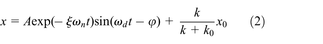
where A is the amplitude, ξ is the damping ratio, ωn is the natural frequency, t is the collision time, φ is the damping angle, and ωd is the oscillation frequency.
Apparently, the collision time can be determined by the smallest positive eigenvalue of

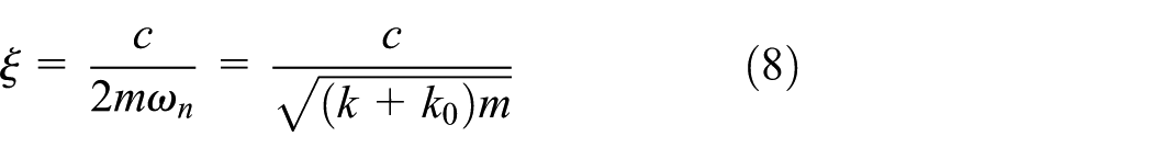
where Δt is the interval time of collision; sn, cs, ωn, ωd, and A can be expressed as


Therefore, the recovery coefficient e can be expressed as

where

In order to obtain the expression of the recovery coefficient further, the initial elastic position is considered as zero. Therefore, the interval time of collision can be obtained according to equation (3)

Substitute equation (9) into equation (6), the corresponding recovery coefficient can be obtained as follows

Analysis of vibration response
According to the configuration of non-contact ultra-quiet Stewart spacecraft as shown in the above section, the vibration induced by collision is mainly related to the released energy of the locking device. Since the releasing velocity of the locking device is small, the collision of elastic displacement restriction is a kind of point-to-point contact. Therefore, the impact force F(t) during collision can be expressed as

Substituting equation (2) into equation (11) yields

Obviously

Simplifying the above equation yields

Obviously, it can be seen that the vibration response is bounded from the above equations.
Analysis of collision motion
Since the collision of elastic displacement restriction is the point-to-point contact, Hertz formula is appropriate to determine the damping of the elastic displacement restriction, and the motion equation as shown in equation (1) can be expressed as

The difference between equations (1) and (15) is that the damping of the elastic displacement restriction c is replaced by the damping function D(x).
The velocity v can be expressed as follows according to the recovery coefficient

The recovery coefficient is mainly related to the material properties of elastic displacement restriction and the releasing velocity of the locking device. The least squares method is used to fit the recovery coefficient

where αi is the least squares coefficient.
Taking the first-order approximation of equation (17), the loss of kinetic energy ΔT after the collision can be expressed as

Ignoring the higher terms, the loss of kinetic energy can be expressed as

In the compression phase of collision, the initial kinetic energy would be transformed into the maximum deformation energy. In the recovery phase of collision, the deformation energy would be released and transformed into kinetic energy of the system. Suppose that the maximum compression is xm; thus, the initial kinetic energy can be expressed as

Thus, the initial kinetic energy can be obtained as follows

Substituting equation (21) into equation (19), the loss of kinetic energy can be obtained as follows

For any deformation x (0 < x < xm) during the compression phase of collision, the corresponding velocity vc satisfies


The energy loss during collision is related to the damping function D(x); thus

According to the research of Hunt and Grossley, the damping function D(x) can be expressed as

where λ is the hysteretic damping coefficient.
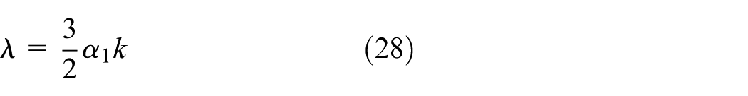
Substituting the expression of damping function into equation (25) and integrating, we can obtain

Comparing equation (27) with equation (23), the hysteretic damping coefficient can be obtained as follows
Therefore, the motion equation as shown in equation (15) can be expressed as

Based on the above analysis, the system suffered the greatest impact force if vc = 0 in each collision and thus

Simplifying the above equation yields

Therefore, the elastic position can be obtained as follows

Obviously, it can be seen that reducing the releasing velocity of the locking device is useful to improve the stabilization time.
Two-echelon collaborative control
The vibration behavior induced by impact force has interference on the attitude performance of non-contact ultra-quiet Stewart spacecraft due to the installation of non-contact voice coil actuators. Therefore, a two-echelon collaborative control algorithm is proposed to reject the influence of collision and to realize the vibration isolation and stability performance of non-contact ultra-quiet Stewart spacecraft in this section.
Attitude control of PM
As stated in the above section, ultra-quiet devices and attitude sensors are installed in the PM of non-contact ultra-quiet Stewart spacecraft. Thus, the PM is a quiet module, the stability control performance of which is related to various disturbances, such as environmental torques, disturbance torques induced by impact force, and performance of non-contact voice coil actuators. To realize the vibration isolation and attitude control, the active control using the non-contact voice coil actuators is studied in this section. Therefore, the dynamic modeling of PM can be expressed as


where
The attitude control goal of PM is to achieve the three-axis stability by eliminating the effect of disturbance torques and thus

Let the error of angular velocity be denoted

Meanwhile, the integral sliding mode surface

The derivative of the sliding mode surface is

Substituting equation (33) into equation (38), the above equation can be expressed as

The Lyapunov function is considered as follows

Thus, the time derivative can be expressed as

The angular velocity of PM can be observed by attitude sensors. Therefore, the sliding mode control law for the control torques of non-contact voice coil actuators is defined as

where
Thus

According to Lyapunov stability theorem, when t → ∞,
Collaborative control of SM
As stated in the above section, the reaction wheels, solar panels, and thrusters are installed in the SM, so that the dynamic modeling of PM is more complicated. Without loss of generality, the kinetic equation of SM with single flexible attachment can be expressed as

where
The relative angular velocity relationship between PM and SM can be expressed as

where

The control goal is to make the SM track PM accurately and thus

In accordance with the transfer order 3-1-2, the attitude transformation matrix is shown as follows 30

where c and s are the abbreviations of cos and sin, respectively, and ψ, θ, and φ denote the three-axis attitude angle, respectively.
Thus, the attitude transformation matrix

And


Meanwhile, the integral sliding mode surface is defined as

The derivative of the sliding mode surface is

Substituting equations (46), (50), and (51) into equation (53), the above equation can be expressed as
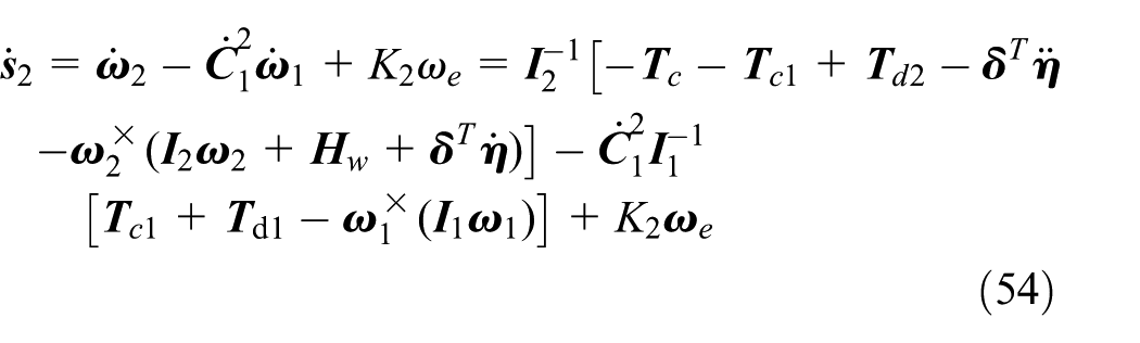
In addition, the angular momentum is small during stable operation due to the small angular velocity of the SM. The term

The coefficient
Define

The Lyapunov function is considered as follows

Thus, the time derivative can be obtained as follows
In order to satisfy the condition of

where
Thus

It can be seen from the above equations, when t → ∞,
Numerical simulation
Simulation conditions
Suppose that the subject non-contact ultra-quiet Stewart spacecraft flies in a circular dusk–dawn Sun-synchronous orbit with an altitude of 500 km. The parameters of the spacecraft and the environment are listed in Table 1.
The parameters of the subject non-contact ultra-quiet Stewart spacecraft and the environment.
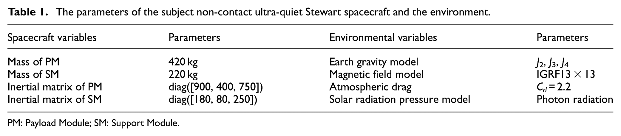
PM: Payload Module; SM: Support Module.
To validate the vibration isolation and the stability performance of non-contact ultra-quiet Stewart spacecraft under collision, the initial conditions of numeric simulation are listed in Table 2. The electromagnetic locking device is installed along the z-axis, so the releasing velocity is along the z-axis in the numerical simulation.
The parameters of the initial conditions.

PM: Payload Module; SM: Support Module.
Simulation results
The simulation results of the proposed two-echelon collaborative control of non-contact ultra-quiet Stewart spacecraft are shown in Figures 3–9.

Comparison of the disturbance torques.

Attitude pointing along the x-axis.

Attitude pointing along the y-axis.

Attitude pointing along the z-axis.
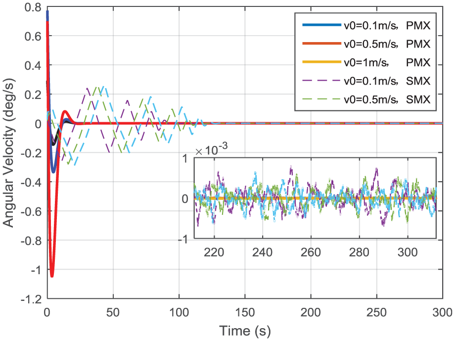
Angular velocity along the x-axis.
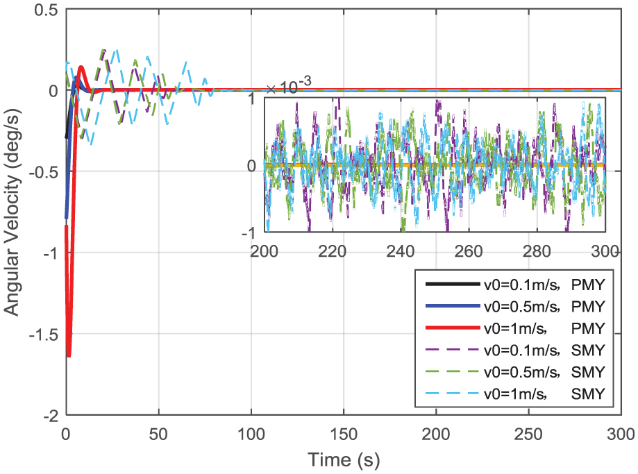
Angular velocity along the y-axis.
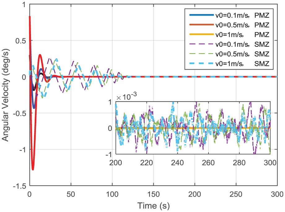
Angular velocity along the z-axis.
Figure 3 depicts the comparison between the environmental torques and the collision torques. The environmental torques consists of the gravity gradient torque, atmospheric torque, solar radiation torque, and magnetic torque. Obviously, it can be seen that the collision torques of the three categories as shown in Table 2 dominate the disturbance torques during the collision phase, while the environmental torques dominate the disturbance torques during the stable phase.
Figures 4–6 demonstrate that the attitude pointing of PM and SM along the three axes tends to attenuate gradually, which means that the influence of collision can be rejected. Since the inner dynamics of PM is ultra-quiet and the attitude control of PM is actuated by an accurate non-contact voice coil, the collision rejection of PM costs less time than SM. Meanwhile, the simulation results indicate that reducing the releasing velocity of the locking device is useful to improve the stabilization time of PM and SM, which is the same as the conclusion shown in section “Analysis of collision motion.”
Figures 7–9 demonstrate that the angular velocity of PM and SM along the three axes also tends to attenuate gradually. The simulation results indicate that the stability performance of PM is much better than that of SM, which means that the coupling influence of vibration behavior of SM cannot be transmitted to PM. Thus, the vibration isolation and stringent stability performance can be implemented.
Apparently, the above-mentioned simulation results demonstrate that the proposed two-echelon collaborative control algorithm is effective to guarantee both perfect collision rejection and stringent stability performance for non-contact ultra-quiet Stewart spacecraft.
Conclusion
The equivalent collision modeling with a small releasing velocity and the two-echelon collaborative control of non-contact ultra-quiet Stewart spacecraft are studied to guarantee the collision rejection and stability performance in this article. The simulation results demonstrate the validity and effectiveness of the proposed design and indicate that reducing the releasing velocity of the locking device is useful to improve the stabilization time. It coincides with the theoretical analysis of collision motion.
The non-contact ultra-quiet Stewart spacecraft has a wide range of applications in future space missions. Besides the investigation of this article, collision rejection control with a large releasing velocity and wireless transformation of energy and signal will be the focus of future studies.
Footnotes
Handling Editor: Jose Ramon Serrano
Declaration of conflicting interests
The author(s) declared no potential conflicts of interest with respect to the research, authorship, and/or publication of this article.
Funding
The author(s) disclosed receipt of the following financial support for the research, authorship, and/or publication of this article: This study was supported by Shanghai Science and Technology Commission (No. 16QB1403500), the National Science Foundation of China (Grant No. 11772185), National Key Program of the Ministry of Science and Technology (No. 2016YFB0500801), Fundamental Research Funds for the Central Universities (No. HEUCFP201770), the Natural Science Foundation of Heilongjiang Province (No. F2015032), and the Harbin Science and Technology Innovation Talent Youth Fund (No. RC2013QN001007s).