
Abstract
The mechanical structure known as Stewart–Gough platform is the most representative parallel robot with a wide variety of applications in many areas. Despite the intensive study on the kinematics, dynamics, and control of the Stewart–Gough platform, many details about these topics are still a challenging problem. In this work, the use of automatic dynamic analysis of multibody systems software for the kinematic and dynamic analysis of the Stewart–Gough platform is proposed. Moreover, a co-simulation automatic dynamic analysis of multibody systems (ADAMS)-MATLAB is developed for motion control of the Stewart–Gough platform end-effector. This computational approach allows the numerical solution for the kinematics, dynamics, and motion control of the Stewart–Gough platform and a considerable reduction on the analytical and programming effort. The obtained results in the three topics (kinematics, dynamics, and control) are validated by comparing them with analytical results reported in the literature. This kind of computational approach allows for the creation of virtual prototypes and saves time and resources in the development of Stewart–Gough platform-based robots applications.
Introduction
Kinematics, dynamics, and control are key issues to be addressed in the development of any robotic system. Kinematic analysis refers to the study of the geometry of motion of a robot. In this analysis, the relation between the geometrical parameters of the robot with the final motion of the end-effector is derived and analyzed. Derivation of the robot motion equations is the main step in dynamic analysis. These equations are essential in the design, analysis, and control of the robotic system. The robot control problem may be characterized as the desired motion of the end-effector. 1,2
For applications in which high precision and low compliance are required or a relatively high load capacity per robot weight is essential, parallel structures are the absolute alternative. 2 The mechanisms proposed by Gough 3 and Stewart 4 were the basis for the development of what is today known as parallel robots. 5 The mechanical structure known as Stewart–Gough platform (SGP) is a fully parallel actuated mechanism with six degrees of freedom (DOFs) and it became into a popular research topic of robotics in the 1980s 6 and this trend has prevailed until today. 7 –10
In general, forward kinematics of parallel manipulators is very complicated because the solution involves systems of coupled nonlinear equations with no closed form and unique solutions. The forward kinematics problem (FKP) of SGP is to compute the position and orientation (pose) of moving platform when limbs lengths are given. 11 In the literature, different numerical and analytical approaches have been proposed to solve this problem either in general or in particular cases. 2,12 The forward kinematics of the SGP has been considered in numerous works by many researchers. A deep analysis of the main articles dealing with this topic, published until 2013, is presented by Taghirad. 2 However, the pursuit of effective methods to solve the FKP of the SGP continues. He et al. 11 developed an adaptive algorithm using a multitask Gaussian process learning method to solve the FKP of two different SGP configurations. The obtained simulation results show that the proposed algorithm can achieve a superior real-time performance compared with other reported algorithms. Mahmoodi et al. 13 proposed a novel method for real-time FKP solution of the SGP using six measurements on three legs joints consisting of the rotations of three legs in two directions. After the application of the method on a laboratory sample SGP, it is observed that while the method has reasonable accuracy, it is simpler in implementation, more practical, less expensive, and easier in maintenance in comparison with the conventional method that uses the length measurements of all six legs. Cardona 14 presents a new methodology to deal with the FKP of the SGP based on a multibody formulation which consists of modeling the constraints of movement for all moving parts, especially the joints, and after that, build for each joint, linking the body of the robot, a set of equations that define the constraints on their movement so that the joint variables are included in these equations. He used an iterative algorithm to solve numerically the obtained constraint equations. In order to avoid the problem reported with the orientation (Euler angles) of the moving platform, a generalized coordinate vector using quaternions was applied. This methodology represents an interesting alternative for numerically solving the forward kinematics of SGP. Recently, Gallardo-Alvarado in his book, 15 applies screw theory to obtain the forward kinematic equations of the original Stewart platform. These equations are solved by applying Sylvesters dialytic method of elimination in order to obtain the possible real solution for the moving platform pose. All of these methods require an analytical model based on a system of nonlinear equations which must be solved by numerical methods. Moreover, the FKP is not fully solved by finding all the possible solutions for the analytical equations. Other schemes are needed to find a unique actual pose of the end-effector among all the possible solutions and this aspect is still a challenging problem. 2
The main objectives of the dynamical analysis in parallel manipulators are calculation of internal forces for the design process of the manipulator and study on dynamical properties of the manipulator for controller design. In order to obtain the dynamics of the SGP, many approaches have been applied: bond graphs, 16 the principle of virtual work, 17 the generalized momentum approach, 18 the Newton–Euler formulation, 19 –21 the Lagrangian formulation, 22 or a combination of the last two. 23 All of these approaches result on a set of differential equations which have to be solved to know the dynamic behavior of the SGP.
The control objective in parallel robots is to achieve that the moving platform (end-effector) of the robot accurately follows a desired position and orientation path. 2 The motion control problem for the SGP has been dealt using various control schemes: decentralized proportional-integral-derivative (PID) and feed forward controllers, 2 optimal control with optimal feedback linearization, 9 inverse dynamic control, 2,24 adaptive backstepping tracking control, 25 PID and sliding mode controllers, 26 output integral sliding mode controllers, 27 kinematics and dynamics PID controllers, 28 and smooth integral sliding mode controllers. 29 Most of these control schemes are based on models, so that they need the kinematic and dynamic analysis results in order to be synthesized.
Kinematic analysis (forward kinematics, in particular), dynamic modeling, and control design of the SGP present an inherent complexity. Despite the intensive study in this topic of parallel robots, mostly conducted in the last three decades, additional research still has to be done in this area.
In recent years, co-simulation has become a powerful tool in the engineering systems design. 30 –32 Collaborative simulation or co-simulation consists in application of the specialized software packages that allow the use of more sophisticated models, but at the cost of restricted access to the intermediate results as well as the limited range of possible modifications of models and solution algorithms. 33 Co-simulations allow developers to examine different aspects of a system and they also enable the automatic evaluation of a much larger design alternatives compared to a manual trial-and-error approach. 34 Co-simulation is a prominent method to solve multi-physics problems. Multi-physics simulations using a co-simulation approach have an intrinsic advantage. They allow well-established and specialized simulation tools for different fields and signals to be combined and reused with minor adaptations in contrast to the monolithic approach. 35 Moreover, the use of co-simulations greatly reduces the need for mathematical derivation for the system dynamic parameters. The dynamic analysis of the co-simulation environment provides a real-time visual output which helps to verify the system performance on a virtual prototype. This reduces the need for prototyping the hardware of the system and then testing the control algorithm. Co-simulations save money, time and give ability to modify the system for the user requirements before it has been fabricated. 36
Co-simulation has been applied in the design and analysis of robotic systems, mainly in serial manipulators 30,33,36 and mobile robots. 34,37 The use of these computational tools has proved the advantages mentioned above. In this article, the use of specialized software for multibody systems (automatic dynamic analysis of multibody systems (ADAMS)) for the kinematic and dynamic analysis of the SGP is proposed. Moreover, a co-simulation ADAMS-MATLAB is developed for motion control of the SGP end-effector. This computational approach allows the numerical solution for the kinematics, dynamics, and motion control of the SGP and a considerable reduction on the analytical and programming effort. The obtained results in the three topics (kinematics, dynamics, and control) are validated by comparing them with analytical results reported in the literature. This kind of computational approach allows the creation of virtual prototypes and it can save time and resources in the development of SGP-based robots applications.
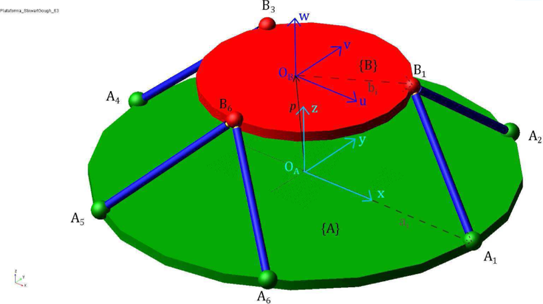
SGP geometrical description
The SGP is a parallel robot with six DOF. It is a fully parallel mechanism which means the number of actuators is equal to the number of DOF. In Figure 1, a schematic of the SGP is shown. The spatial position and orientation of the moving platform is controlled by the length (li, i = 1, 2, …, 6) of six identical linear actuators (limbs). The actuators are connected with both fixed base and moving platform by spherical joints at vertices Ai and Bi, respectively. The vertices Ai lie in the fixed base plane and Bi lie in the moving platform plane. Each limb has a kinematical structure SPS.

Schematic representation of the Stewart–Gough platform.
In order to develop the kinematic analysis of the SGP, two coordinate frames are defined. A fixed frame

Kinematic analysis
A particular class of SGP is considered for the kinematic analysis. The 6 − 6 P SGP has two main characteristics 38 : The fixed base and the moving platform can be geometrically represented by hexagons (the vertices Ai are required to lie on a plane and similarly, the vertices Bi are also required to lie on a plane), and the two hexagons are similar; if one of the platforms is chosen to be a particular hexagon, the other platform has to be a scaled version of the first one (see Figure 1). That is

The numerical parameters used for the kinematic analysis of the 6 − 6 P SGP are presented in Table 1 and they are based on the results presented by Taghirad. 2
Numerical parameters of the 6 − 6 P SGP.

SGP: Stewart–Gough platform.
The scheme presented in Figure 2 is followed in order to verify the obtained results for the kinematic problem of the SGP. First, a typical trajectory for the position and orientation of the moving platform is proposed and this trajectory is used to solve the inverse kinematics, obtaining the limbs lengths. Next, these obtained lengths are considered as inputs for the forward kinematic problem whose outputs are the spatial motion variables of the moving platform (position and orientation). Finally, this last motion is compared with the initial proposed trajectory, verifying the accuracy of the obtained results.

Schematic representation of the kinematic problem.
The analytical solution for the inverse kinematic problem is given by
2

The desired typical trajectory for the position and orientation of the moving platform was taken from graphics given in the Taghirad’s work. 2 From these graphics, for a rest-to-rest motion, third-order polynomials trajectories were obtained. It is important to mention that the trajectory is divided into two parts, an ascendent trajectory (0–1 s) given in equation (4) and a descendent one (1–2 s) given in equation (5)


where x, y, and z correspond to position coordinates of point OB and θx, θy, and θz are the orientation angles given in the screw displacement representation. This pose is given with reference to the fixed frame
The proposed desired trajectories are presented in Figure 3.

Third-order polynomial trajectory for the moving platform pose.
Equation (3) was numerically solved by MATLAB. The results corresponding to the platform limbs lengths are shown in Figure 4. Notice that the inverse kinematic problem has a unique solution.
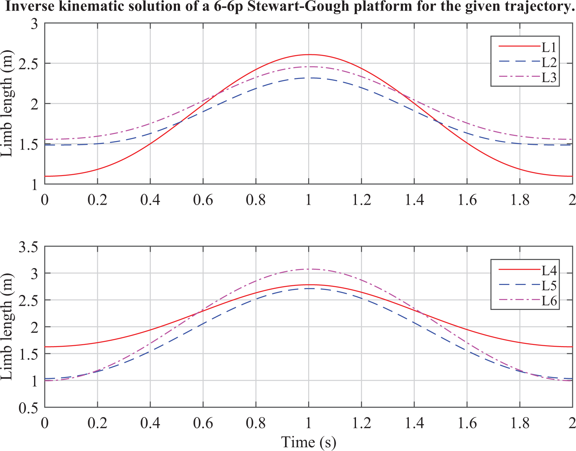
Inverse kinematic solution obtained by MATLAB.
In order to solve the inverse kinematics for the 6-6 SGP, a 3D model was developed in ADAMS (Figure 5) and the pose of moving platform given by equation (4) was induced. The results for the limb lengths are presented in Figure 6. By comparing Figures 4 and 6, it can be observed that the results obtained in ADAMS correspond to those obtained numerically by MATLAB using the analytical model. In specific, the trajectory tracked by each limb length describes the same function in both MATLAB (analytical method) and ADAMS (numerical) solutions. These results prove the effectiveness of solving the SGP inverse kinematics using ADAMS. However, an important limitation was found in the trajectories implementation. The desired trajectory for the pose of moving platform was implemented only in the ascendent part because only one function can be established in ADAMS for the motion of a rigid body.
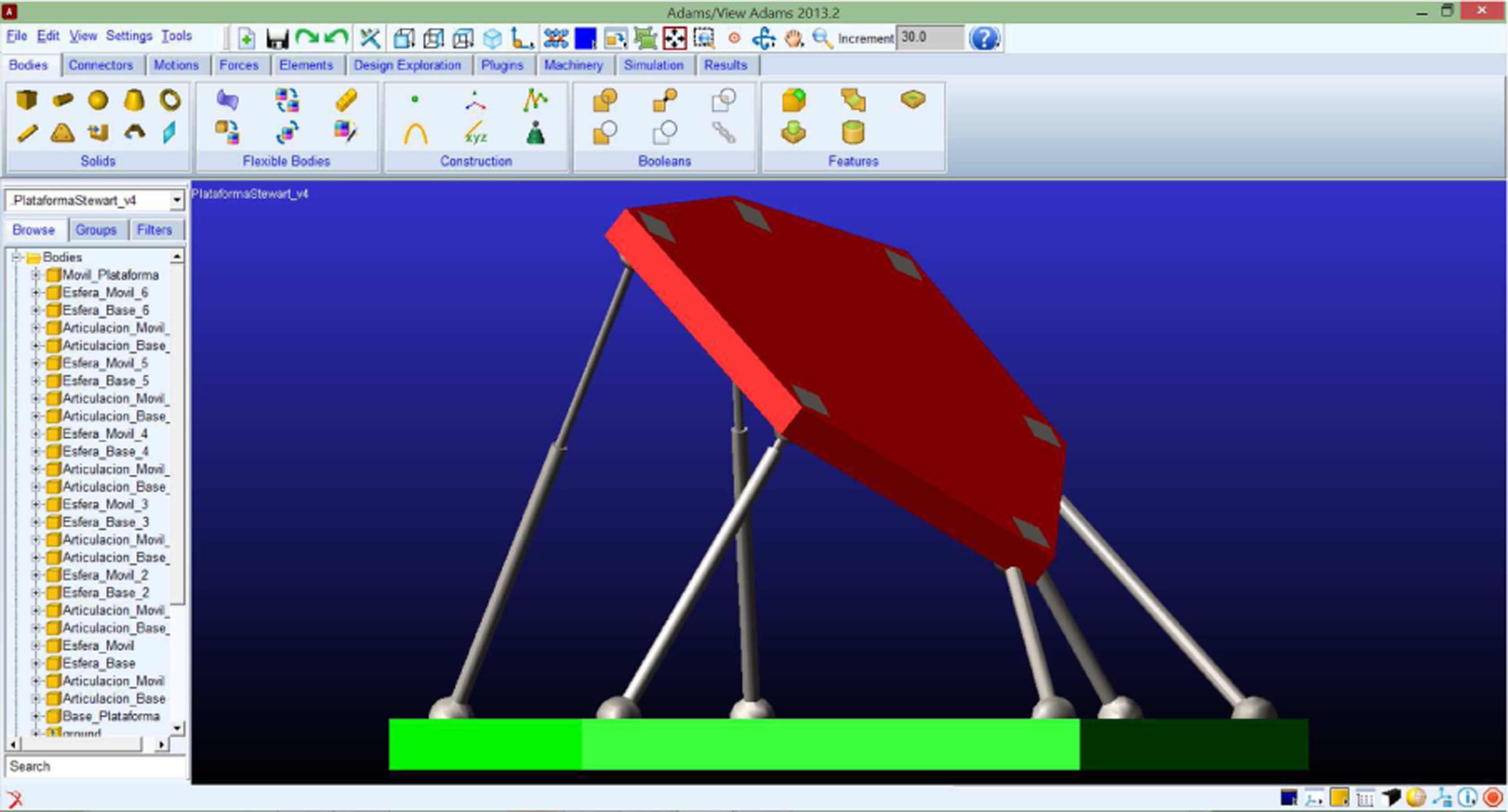
3D model of Stewart–Gough platform for simulation in ADAMS. ADAMS: automatic dynamic analysis of multibody systems.

Inverse kinematics of the SGP in ADAMS. SGP: Stewart–Gough platform; ADAMS: automatic dynamic analysis of multibody systems.
As we mentioned above, the FKP of the SGP has been dealt by different analytical approaches, but the problem is still a challenge. Here, the problem is solved by numerical simulation in ADAMS. Following the scheme of Figure 2, the obtained results for the inverse kinematic problem are used to solve the FKP. The profiles for the limb lengths of Figure 6 are used as inputs and the pose of moving platform is obtained. The results for position and orientation of the moving platform are presented in Figure 7.

Forward kinematics of the SGP in ADAMS. SGP: Stewart–Gough platform; ADAMS: automatic dynamic analysis of multibody systems.
It is important to mention that α, β, and γ are the roll-pitch-yaw Euler angles. To be able to compare this orientation with the desired trajectory, the screw angles given in Figure 3 were transformed in the Euler angles as shown in Figure 8. By comparing Figure 7 with the desired position and orientation of the moving platform given in Figures 3 and 8, we can observe an error of around 6% in the final point of y coordinate and around 5% in the final value of γ orientation angle of the moving platform position. The rest of the pose variables of the moving platform converges to the proposed trajectory. This shows that the FKP of the SGP can be solved without the use of complex analytical methods which involve a considerable programming effort.
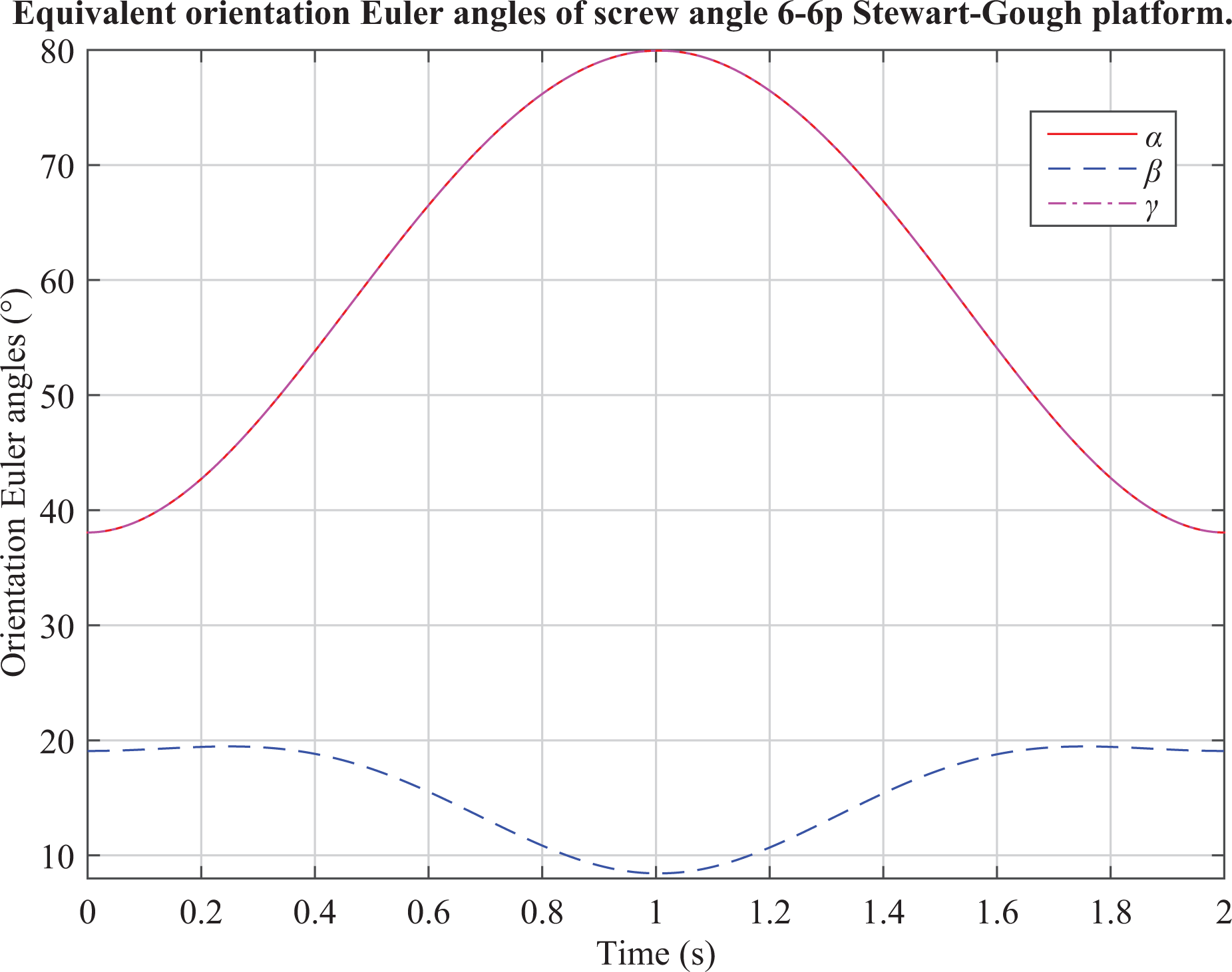
Euler angles for the orientation of the moving platform.
Dynamics and control
The dynamic analysis of parallel robots presents an inherent complexity due to their closed-loop structure. 2 However, this analysis must be carried out in order to design the mechanical components and the control system for the robot. In this section, the results for the forward dynamics and motion control of the 6-3 SGP depicted in Figure 9 are presented. In the 6-3 SGP, the six cylinder-piston limbs meet in a pairwise at three points on the moving platform. 39
The 6-3 Stewart–Gough platform considered for dynamics and control.
The explicit closed-form dynamics of the SGP is given by

where
For the forward dynamics and control simulation, the results presented by Taghirad 2 are taken as a reference. The numerical parameters for these simulations are presented in Table 2.
Numerical parameters of the 6-3 SGP.

SGP: Stewart–Gough platform.
For the forward dynamics analysis, the actuator forces applied to the manipulator are known and the resulting position and orientation of the moving platform is to be determined, as it is indicated in Figure 10.
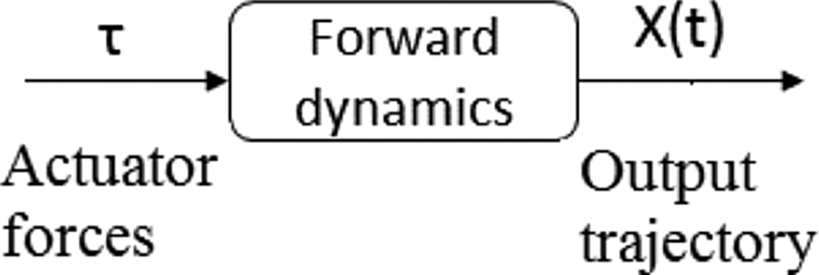
Forward dynamics analysis.
Two simulations are carried out in order to verify the forward dynamics of the 6-3 SGP. In the first one, it is assumed that all actuator forces are zero and the only force acting on the SGP is the gravitation force. The expected motion is only a translation along z-axis with the other translations and all the rotations equal to zero. The results are presented in Figure 11. As it can be observed, the results verify the expected motion and they coincide with the results presented by Taghirad 2 which were obtained by a complex analytical procedure.

Forward dynamics in ADAMS of the 6-3 SGP with gravitation force and without actuator forces. ADAMS: automatic dynamic analysis of multibody systems; SGP: Stewart–Gough platform.
The second scenario is considering the actuator forces equal to −10 kN and neglecting the gravitational force. The results are shown in Figure 12. In order to compare the results with the reported in the literature, no physical constrains are considered for the platform motion. The resulting motion is only translation along the z-axis even after the moving platform reaches the fixed base and becomes oscillatory with the same amplitude. A sequence of the position of the moving platform along the simulation in ADAMS is shown in Figure 13. The obtained motion coincides with the analytical results presented by Taghirad. 2

Forward dynamics in ADAMS of the 6-3 SGP with constant actuator forces. ADAMS: automatic dynamic analysis of multibody systems; SGP: Stewart–Gough platform.

Motion of the moving platform of the 6-3 SGP with constant actuator forces. SGP: Stewart–Gough platform.
With the forward dynamics solved by numerical simulations in ADAMS, the closed-loop control system depicted in Figure 14 is implemented for trajectory tacking problem. The desired trajectory is a third-order polynomial for spatial position of the moving platform with a constant horizontal orientation, as it is shown in Figures 15 and 16.

Block diagram of the closed-loop control system for the 6-3 SGP. SGP: Stewart–Gough platform.

Desired position of moving platform of the 6-3 SGP in the tracking problem. SGP: Stewart–Gough platform.
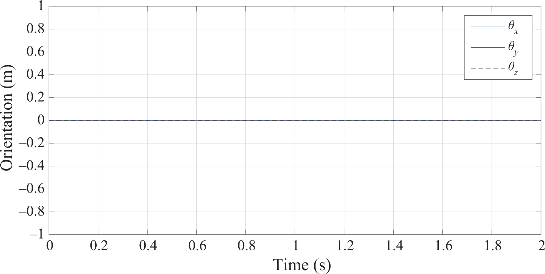
Desired orientation of moving platform of the 6-3 SGP in the tracking problem. SGP: Stewart–Gough platform.
In order to solve the motion control problem, a co-simulation ADAMS-MATLAB Simulink is proposed. Figure 17 describes the main steps of the co-simulation process. As it can be observed in Figure 14, the forces calculated by the control algorithm must be mapped to the forces applied to the system by the actuators, and this mapping is carried out by the Jacobian matrix of the 6-3 SGP. This Jacobian matrix is calculated by a MATLAB function based on the analytical results reported by Taghirad. 2 In Figure 18, the block diagram for the actuator forces calculation is presented.

ADAMS-MATLAB co-simulation process. ADAMS, automatic dynamic analysis of multibody systems.
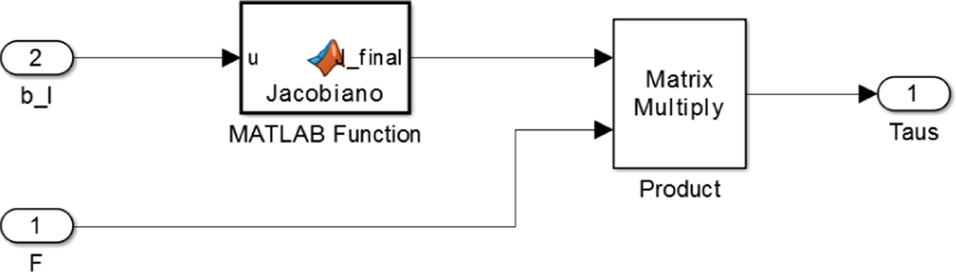
Actuator forces calculation.
The ADAMS model was exported to MATLAB-Simulink environment in order to get the system dynamics and the motion variables for control implementation. The block diagram for the co-simulation of the closed-loop system is shown in Figure 19.

MATLAB-Simulink block diagram for the co-simulation of the 6-3 SGP in closed loop. SGP: Stewart–Gough platform.
The obtained results for the closed-loop system with a proportional-derivative (PD) control are presented in Figures 20 and 21. The PD gains used in this simulation are

Obtained position of moving platform of the 6-3 SGP in the tracking problem. SGP: Stewart–Gough platform.

Obtained orientation of moving platform of the 6-3 SGP in the tracking problem. SGP: Stewart–Gough platform.
By comparing the obtained position and orientation of the moving platform in the virtual prototype with the desired trajectories, we can observe that the motion along the three axes is practically identical. This represents a tracking error near to zero. In the orientation of the moving platform, some oscillations around the desired reference can be observed. However, the magnitudes of the oscillations are only a few decimal of grade which represents a tracking error for the orientation very small.
Conclusion
In this work, an alternative methodology based in the use of ADAMS for the kinematics, dynamics, and control of the SGP has been proposed. Two different configurations were dealt, the 6-6 and the 6-3 SGP. The proposed methodology allows the inverse and forward kinematic analysis and the forward dynamic analysis without the need of complex analytical and hard-working methods. The obtained results were validated by comparing them with numerical and analytical results reported in the literature. Moreover, the kinematic and dynamic results were used in order to synthesize a PD control scheme for a trajectory tracking problem and the controller was implemented by a co-simulation ADAMS-MATLAB showing an accurate performance with very small tracking errors only in the orientation of the moving platform. The use of computational approach allows the creation of virtual prototypes and it can save time and resources in the development of SGP-based robots applications.
Footnotes
Acknowledgements
The authors wish to thank to National Council of Science and Technology (CONACYT) from Mexico for the support in this work by the Catedras-CONACYT program.
Declaration of conflicting interests
The author(s) declared no potential conflicts of interest with respect to the research, authorship, and/or publication of this article.
Funding
The author(s) disclosed receipt of the following financial support for the research, authorship and/or publication of this article: The authors wish to thank to PRODEP-SEP, Mexico for the financial support for this paper.