
Abstract
The material used for the study is bi-axial glass cloth with epoxy resin. Two sets of laminates were manufactured using vacuum assisted resin transfer moulding, one laminate with parent material (P1, P2) and the other laminate with graphene platelet nanopowder (P1-GPN, P2-GPN). For the graphene platelet nanopowder samples, addition of 0.1% weight of graphene platelet nanopowder is mixed with epoxy resin. Three different tests such as tensile, compression and impact were conducted on the composite material. There was an increase of 11.18% and 33.4% in tensile strength, 26.4% and 24.6% in compression strength when compared to the parent samples of 2 and 3 mm thickness, respectively. This strength was obtained with the reduction of fibre content when compared to other research works. Also high-velocity impact test using gas-gun method was performed on parent and blended samples. The energy absorption levels of blended samples were 9.2% and 8.2% higher than the parent samples of 2 and 3 mm thickness, respectively. Therefore, this study reveals that the addition of graphene platelet nanopowder with the parent material has increased the strength of the composite tremendously.
Keywords
Introduction
At present, the usage of technology of composite materials is rampant in so many areas of applications such as automobile sector, marine, aerospace structures and buildings. The inherent properties of light weight and high strength to weight ratio of the composites are utilized in all the fields of engineering, medicine and so on. A Afrouzian et al. 1 studied the performance of nano-silica particles on glass fibre–reinforced polymer (GFRP) composite under gas-gun impact test method. The results revealed that addition of 0.5% weight of nanoparticles yielded maximum tensile strength and energy absorption while 3% weight gives higher flexural strength. A Khomenko et al. 2 proposed for acquiring high-resolution, rapid and non-contact optical transmittance scans of impacted GFRP samples. The authors also developed an advanced data analysis to identify the delamination at every point of the scan. Balaganesan et al. 3 investigated GFRP composite with nanofillers and without the addition of nanofillers under impact loading conditions using gas-gun method. The authors studied the ballistic limit and energy absorption under the impact conditions and the dispersion of nanoclay in the matrix. B Hao et al. 4 studied that GFs with graphene coating provide more details on the damage accumulation in FRPs. Papageorgiou et al. 5 studied the mechanical properties of grapheme-based nanocomposites. The authors suggest that the assumption followed generally for the usage of filler material is not dependent on the matrix and is not correct. Inclusion of small amount of graphene into the parent material gives a significant contribution in reinforcement of the final material. Eliopoulos et al. 6 proposed a 3D progressive damage constitutive model for the composite under monotonic loading conditions (both tension and compression). The model was also validated by comparing the results with the experimental data of the composite. H Ulus et al. 7 manufactured hybrid nanocomposite and studied its mechanical properties. The nanoparticles used are boron nitride (BN) nanoplatelets and multi-walled carbon nanotubes (MWCNTs). It was concluded from their study that the modified epoxy with nanoparticles resulted in increase in toughness of the composite. Also the nanoparticle reinforced composite had better ductility when compared to neat epoxy. Zhu et al. 8 investigated that the tensile properties got degraded with higher temperature and with an increase in immersion time of alkaline solution. The authors concluded that the degradation rate got reduced when epoxy nanocomposite was used as a matrix material. I Choi 9 investigates analytically low-velocity impact responses and its damages in the composite laminate. Depending on the structural behaviour of the composite laminate, a finite element equation is developed and a computational programme is coded. J Wei et al. 10 studied the dispersion of graphene nanoplatelets in epoxy and also its mechanical properties. It was found that 0.3% by weight of graphene yielded better tensile strength and storage modulus. The results also predict that the dispersion rate depends on sonication time and temperature. J Liang et al. 11 studied the tensile properties of polypropylene composite with the inclusion of graphene nanoplatelet (GNP) fillers. The experimental results show that there is an increase in the tensile strength and Young’s modulus of the composite. Due to this addition of filler material (GNP), the tensile elongation at break is decreased with an increase in the GNP weight fraction. KK Panchagnula and P Kuppan 12 investigated the effect of MWCNTs on GFRPs. For this, 0.1%, 0.2%, 0.3% and 0.4% by weight of MWCNTs were mixed with epoxy resin. It was found that 0.3% MWCNTs had better mechanical properties than other GFRPs. Libonati and Vergani 13 investigated the damage assessment by means of thermographic analysis. This method allows both qualitative and quantitative analyses in a short duration. M Rahman et al. 14 studied the ballistic impact performance on GFRP with modified epoxy resin. In their study, amino-functionalized MWCNTs were mixed with epoxy and impact test was carried out using gas-gun method with a spherical bullet under different velocities. The authors also determined the ballistic limit velocity by means of statistical methods. N Domun et al. 15 investigated the mechanical properties of epoxy nanocomposite. The nanomaterial used for this study is functionalized graphene nanoplatelets (f-GNP) at low filler content. It was observed that the fracture toughness of the nanocomposite increased by 50% while adding 0.25% weight f-GNP when compared to neat epoxy composite. Also coefficient of thermal expansion and glass transition temperature showed a small increase with the addition of 1% weight of f-GNP. Naik et al. 16 studied the impact response of glass–carbon fibre with epoxy resin–hybrid composite. Drop weight impact test was carried out on carbon, glass and hybrid reinforcements. The experimentation revealed that the notch sensitivity of hybrid composite was less when compared to carbon and glass composites. Naresh et al. 17 studied glass, carbon and hybrid/epoxy composites in order to obtain its tensile strength. Also Weibull distribution is used to measure the variability of tensile strength of cross-ply laminates. Naresh Kumar et al. 18 investigated the micro end milling operation of GNP and MWCNT filled nanocomposite. The authors predicted that the micro cutting forces are higher for GNP-filled Polycarbonate (PC) nanocomposite than the plain PC. Also they have found that there is a tremendous improvement in the dimensional accuracy of the GNP and MWCNT machined surface specimen. Ortiz de Mendibil et al. 19 studied low-velocity impact behaviour on fibre metal laminate. The authors emphasized on damage mechanisms, dissipated energy and peak force of the drilled holes and compared it with those of the standard samples without holes. Pattabhi et al. 20 studied the crack particle method simulation of dynamic fracture of composites. The author predicts the residual impact velocities by this method. Ravandi et al. 21 investigated the performance of low-velocity impact (drop weight) on woven flax fabric with epoxy under stitched and unstitched fabric conditions. The outcome of the experimentation reveals that the propagation of in-plane cracks is facilitated by the stitching process while the delamination is not the predominant mode of damage in stitched and unstitched woven flax composite. Umer et al. 22 studied the effect of graphene oxide nanoparticles on epoxy/glass fibre composites and concluded that the addition of 0.1 wt% increased 30% flexural strength and 21% flexural modulus. Also the authors predicted that with the addition of 0.2 wt%, graphene oxide results in premature resin gelation with much slower resin infiltration time. Venkatanarayanan and Joseph Stanley 23 studied the impact response of intermediate velocity of bullet on GFRP laminates with three different types of resin. The above three types are epoxy, hybrid resin and hybrid with MWCNT in different proportions (0.1 wt%, 0.5 wt% and 10 wt%). The panels made of hybrid resin with MWCNTs absorbed higher impact shock while the plates without MWCNT absorbed less impact shock. Also the addition of higher percentage of MWCNTs yields less vibration damping characteristics and this happens due to the entanglement of MWCNTs in the resin. X Zhang et al. 24 investigated that the MWCNTs played an important role in the energy absorption capacity of GFRPs. Due to the modified GFRPs, it has got higher tensile and flexural strength and hence the failure strain. Y Li et al. 25 studied carbon fibre–reinforced plastics with graphite nanoplatelet–modified epoxy resin and predicted that the nanoplatelet improved low interlaminar mechanical, thermal and electrical properties of the composite. Also this study concludes that the flexural modulus and the interlaminar shear strength increases with the addition of 5 wt% graphite nanoplatelet.
According to Libonati and Vergani, 13 it is difficult to estimate precisely the mechanical properties of the composite, because of its manufacturing processes and its testing methods. Due to these conditions, variations are there in the properties of composites. The current work identifies this gap and adopts vacuum assisted resin transfer moulding (VARTM) method for making up the laminates. Thus, by utilizing VARTM manufacturing process, and to find out the enhancement in the mechanical property of bi-axial glass fibre–reinforced composite, various tests such as tensile, compression and impact tests are conducted. The results show that there is tremendous increase in the tensile strength of the composite when compared to other research studies. 13 From various literatures, the impact test on the bi-axial (±45) E-glass/epoxy composite is found to be a novel venture. Also, in this work, graphene platelet nanopowder (GPN) of 0.1% weight is blended with the epoxy resin and the same specimen is tested and compared with the parent material. Experimental results show that the GPN specimen yielded better results than the parent material.
Material used and experimental methods
The material used for the study is bi-axial non-crimp glass cloth of 600gsm aerial density supplied by Easy Composites, UK. Laminates are made using VARTM method. Bisphenol-A-based epoxy resin (LY556) and hardener (HY951) are mixed to a ratio of 10:1 by weight for the preparation of laminates. The epoxy resin and hardener were purchased from Javanthee enterprises, Chennai. The properties of the resin and hardener are given in Tables 1 and 2. Two different thicknesses of 2 and 3 mm laminates were made. For the 2-mm thickness laminate, four layers of bi-axial glass cloth of size (300 × 300) mm are used. Similarly, for the 3-mm thickness laminate, six layers of bi-axial glass cloth of size (300 × 300 ) mm are used. The tensile and compression specimens were cut according to the ASTM standards. The tensile specimen of dimensions (250 × 25 × 2) and (250 × 25 × 3) were according to ASTM D3518 26 and the compression specimen of dimensions (100 × 10 × 2) and (100 × 10 × 3) were according to ASTM D6641. 27 Similarly, two sets of laminates were made with GPN (GPN Type-1) for 2 and 3 mm thicknesses. GPN (Type-1) is a black powder with a minimum of 99.5% carbon with 6–8 nm of thickness, purchased from SRL (Sisco Research Laboratories, Mumbai), is blended with epoxy for making the GPN laminates.
Properties of epoxy resin (Araldite LY556).

Properties of hardener (Aradur HY951).

The SEM image of GPN with a particle size of 3 µm is shown in Figure 1. It is known that the weight of composite is equal to the sum of the weight of fibres and matrix. It is represented by the equation as wc = wf + wm, where wc is the weight of composite, wf is the weight of fibre and wm is the weight of matrix.

SEM image of GPN.
Thus, the resin weight is calculated using equation (1)

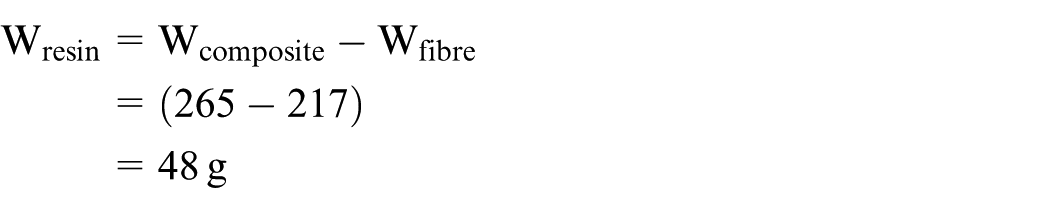
Using equation (1), the resin weight for the 2-mm thickness laminate (four layers) is calculated as follows
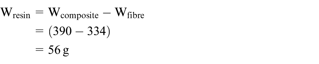
Similarly, the resin weight for the 3 mm thickness laminate (six layers) is calculated as
A sample calculation is shown in the above two resin weight calculations for 2 and 3 mm thickness laminates, respectively.
After calculating resin weight, the volume of the fibres in the composite is calculated using

For the above calculation, the density of the fibres is taken as 2.54 g/cc. Then for the determination of fibre/resin volume ratio, equation (3) is used

Now to determine the matrix volume ratio, the following equation is used

From the above equation (4), resin volume ratio is calculated for 2- and 3-mm thickness laminates. Using the above relations from equations (1)–(4), for the 2-mm thickness laminate, the resin volume ratio is 0.3267 (32.67%). Then using the relationship given in equation (5)

fibre volume ratio is achieved as 0.6733 (67.33%) with the consideration of zero voids in the composite (Vvoids = 0). Similarly, for the 3-mm thickness laminate, the resin volume ratio is 0.2686 using the above stated equations. Finally, the fibre volume ratio for the 3-mm thickness laminate is 0.7314. Therefore, to make the GPN laminate, initially epoxy resin is stirred mechanically for 3 h and then 0.1% weight of GPN is mixed with epoxy according to Umer et al. 22 and stirred again for 4 h. After this process, one part of hardener (which means for example: 200 g of epoxy resin is weighed, then 20 g of hardener is added to it) is mixed with the blended epoxy and immediately infused to produce the GPN laminate. In this VARTM method, the infiltration front on the top face was uniform across the width while the flow pattern on the lower surface was non-uniform and it depends on the stitching spacing. Also this process was used for manufacturing the laminates because there was complete wetting of fibres with 0.1% GPN according to Umer et al. 22 Then it is allowed to cure for 8 h at room temperature and later the tensile, compression and impact specimens were cut using abrasive water jet cutting machine.
Tensile test
Tensile test was conducted on MTS Insight Electromechanical machine of 100 kN capacity. The test was conducted with a speed of 2 mm/min until fracture occurs. The specification of the sample is given in Table 3. The above test was carried out according to ASTM D3518 with sample dimensions of (250 × 25 × 2) and (250 × 25 × 3) mm, respectively.
Specification of the samples.

GPN: graphene platelet nanopowder.
The tensile test results are shown in Table 4. Test was performed four times and the variation of stress for 2 mm parent sample was between 187 ± 2 MPa and the variation of strain was between 0.175 ± 1. Similarly, the variation of stress for 3 mm parent sample was between 136 ± 5 MPa and the variation in strain was between 0.175 ± 2. Also the variation of stress for the 2 and 3 mm with GPN samples were 211 ± 3 and 205 ± 5 MPa, respectively. Similarly, the variations in strain for the 2 and 3 mm with GPN samples were 0.193 ± 2 and 0.216 ± 4, respectively. Libonati and Vergani 13 investigated using the same material with 10 layers and proved the tensile strength as 142 ± 3 MPa, but the present work involved four layers (2 mm) of bi-axial glass–reinforced composite and yielded 187.394 MPa. Therefore, with the reduction of fibre content, the present work yielded 22.62% increase in tensile strength with four layers when compared to research work. 13 J Liang et al. 11 predicted that the addition of GNP improved tensile properties of the composite and in the same way by the addition of GPN as filler material increases the stability of the composite to withstand higher load due to the fine adhesion of GPN with the epoxy matrix. Due to this, initiation of matrix de-bonding and crack bridging takes a longer time than the general practice which ultimately leads to an increase in the tensile strength of the composite.
Tensile test.

GPN: graphene platelet nanopowder.
Figure 2 shows the SEM image of GPN specimen after fracture in the tensile test. It is represented with a particle size of 50 µm in Figure 2. Various damages that occur in a tensile test are clearly represented such as matrix de-bonding, crack bridging, agglomeration and bifurcation. Crack gets initiated from the matrix and gets propagated which results in the entire matrix de-bonding. It is also seen in the image that there is a cluster (agglomeration) of matrix material present on the surface. Also bifurcation is observed in the fractured surface which means the matrix gets separated into two branches. This bi-axial non-crimp GFRP composite with GPN and parent material has extreme fibre scissoring damage at the fracture point. Therefore, it takes the shape of a spiky failure.

SEM image of fractured specimen (with GPN) – where yellow arrow represents crack bridging.
Compression test
Compression test was conducted on MTS Insight Electromechanical machine of 100 kN capacity. The specimen was held between the compression fixtures and the load was applied at a speed of 2 mm/min. The compression test samples were cut according to ASTM D6641 whose dimensions were (100 × 10 × 2) and (100 × 10 × 3) mm, respectively.
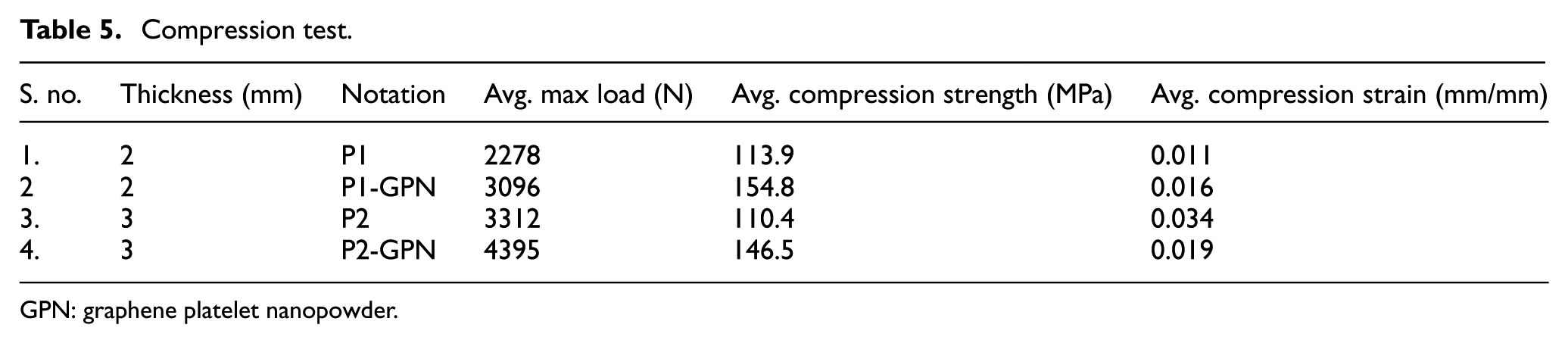
From Table 5, the following points are inferred. The variation of compression strength for the 2 mm parent sample is between 113 ± 4 MPa and for 3 mm parent sample is between 110 ± 3 MPa. Similarly, the variation of compression strain for the 2 and 3 mm parent samples are 0.011 ± 2 and 0.034 ± 3, respectively. Also the variation of compression strength and strain for the 2 mm with GPN samples are 154 ± 5 MPa and 0.016 ± 4 while for the 3 mm with GPN samples are 146 ± 6 MPa and 0.019 ± 3, respectively.
Compression test.
GPN: graphene platelet nanopowder.
High-velocity impact test
Impact test was performed using gas-gun method wherein the compressed gas-gun bullet penetrates the specimen which was held in the fixture. The set-up for the impact test consists of compressed gas-gun, target holder, data acquisition system with Phantom camera control application software, and display unit to measure the time response of the bullet penetrating the panel and also to measure the velocity of the bullet.
The schematic representation of the impact test rig (gas-gun method) is shown in Figure 3. The pressure maintained in the cylinder is 15 bar. The specimen (150 mm × 150 mm) was fixed in the target holder vertically, as shown in Figure 4. The impact test was carried out according to ASTM E399. 28

Schematic representation of gas-gun impact set-up.

Experimental set-up – impact.
The hemispherical bullet made of mild steel with a mass of 8 g, was made to hit the target with an impact velocity of 140–150 m/s at the time of strike. Such a test was conducted on both the GPN sample and parent sample of 2 and 3 mm thicknesses. The kinetic energy absorbed by the panels is calculated using equation (6)

where m is the mass of the projectile (kg), Vi is the initial striking velocity of the bullet (m/s) and Vr is the residual velocity of the bullet after penetration (m/s).
From Table 6, it is clear that the impact energy is greater for with GPN specimens than the parent material.
Impact test.

GPN: graphene platelet nanopowder.
Results and discussion
Tensile result
From Table 4, it is clear that the GPN specimen has better tensile strength than parent material. It is nearly 11.18% higher than parent sample of 2 mm thickness and 33.4% higher than parent sample of 3 mm thickness. This was achieved due to the blending of GPN with the epoxy resin. Similarly, while comparing the tensile strength of 2 and 3 mm parent samples (P1, P2), there is an increase of 27.14% in the 2 mm thickness specimen. But when 2 and 3 mm thickness with GPN specimen (P1-GPN, P2-GPN) are compared, it is observed that there is an increase of 2.8% in the tensile strength of the composite with 2 mm thickness. This occurs because, as the cross-sectional area decreases, load bearing capacity also get decreased while the tensile stress increases. According to Hooke’s law stress is directly proportional to strain. This is clearly observed from the readings of Table 4 and the graphical representation of the stress versus strain is shown in Figure 5. This is particularly achieved because of the GPN dispersion with the epoxy resin which increases the load bearing capacity of the composite. It is also due to the adhesion of GPN with the matrix according to Umer et al. 22

Stress versus strain for the parent material and with GPN samples of 2 and 3 mm thickness tensile specimen.
It is inferred that the GPN specimen exhibits higher percentage of elongation than the parent specimen. The property of GPN adds strength and toughness to the composite which results in higher ultimate tensile strength as stated by X Zhang et al. 24 and J Liang et al. 11
Compression result
Compression test results are shown in Table 5. From Table 5, it is clear that 2 and 3 mm with GPN specimen have higher compressive strength than the parent material. It reveals that with the inclusion of filler material increases the compression strength by 26.42% and 24.6% of GPN samples when compared to parent material of 2 and 3 mm, respectively. Also when 2 and 3 mm parent samples are compared, the compression strength is 3% higher for 2-mm-thick specimen. There is an increase of 5.36% in the compression strength of P1-GPN specimen when compared to P2-GPN specimen. J Liang et al. 11 revealed that the addition of GNP improves the tensile strength and Young’s modulus of the composite. Thus, J Liang et al.’s 11 prediction holds good for the present work and it has been proved that the tensile, compression and the energy absorbed by the GPN specimen is higher when compared to parent material. The graphical representation of compression stress versus strain is shown in Figure 6. It is observed from this test, that by adding 0.1% weight of GPN to the resin 22 makes the composite stronger and that due to the inherent platelet structure of graphene nanopowder increases the bonding nature of fibre and matrix material.

Compression stress versus strain for the parent material and with GPN sample of 2 and 3 mm thickness sample.
Impact result
For the 2 mm thick plate the working pressure was kept at 13 bar. The initial velocity with which the bullet strikes the plate was 150 m/s and the residual velocity after penetration was 100 m/s and 105 m/s for with GPN sample and parent sample. Therefore the energy absorbed by the 2 mm thickness plate with GPN is 9.2% higher than the parent sample. For the 3 mm thickness specimen, the working pressure was kept at 11 bar. The initial velocity of the bullet was 145 m/s and the residual velocity after penetration was 100 and 105 m/s for with GPN sample and parent sample. Thus, the energy absorbed by 3 mm thickness specimen with GPN is 8.2% higher when compared to parent sample. When parent samples and GPN samples of 2 and 3mm are compared, energy absorption by the 3 mm plate is 12.8% and 11.8% higher than the 2 mm plate.
Figure 7 shows the image of the impact tested specimen at the top surface and the bottom surface. The damaged area of the top surface is less than the bottom surface. Also the bi-axial nature of the glass cloth plays a major role and it is clearly visible in the back face as a diagonal of the square shaped impact specimen. As observed, from the image due to the impact of the hemispherical bullet, the damages are prone to the bi-axial direction (ie) in the 45° orientation. The energy absorbing nature of the bi-axial glass fibre–reinforced composite shows enormous amount of delamination at the bottom surface of the impact specimen when compared to the top surface. This is due to the piercing nature of the bullet. Therefore, a conical shape is observed at the bottom surface of the specimen.
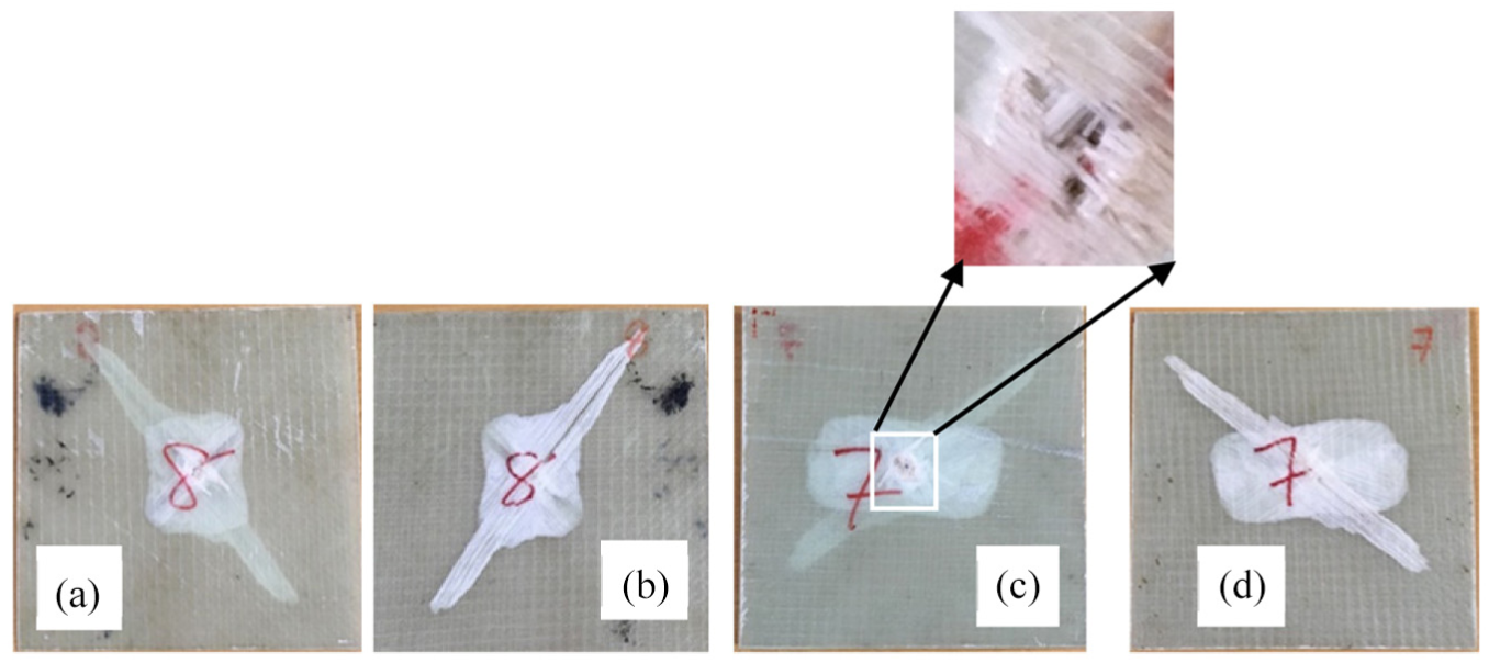
Impact tested specimen – (a) and (c) show the top surface of 2 and 3 mm specimen, (b) and (d) show the bottom surface of 2 and 3 mm specimen.
Figure 7(b) and (d) shows the pullout and separation of fibres due to the sudden impact at the bottom surface. Since the GFRP is of bi-axial nature, fibres aligned in one direction gets pulled out and separated to a larger extent while the fibres in the other direction are restricted and its damage is spread out and it covers a rectangular portion. Figure 7(a) and (c) shows the front face of the impact tested specimen. The damages such as fibre breakage and matrix cracking occur due to the sudden impact of the bullet. Therefore, there is a complete perforation in the specimen at the front and there is a conical shape formation of fibre pullout at the bottom surface of the specimen. From the above Figure 7(a) and (c) and from Table 6, it is understood that as the velocity of the bullet is increased, the time of contact between the projectile and the specimen decreases which results in the damage prone area to be higher and there is a complete perforation in the specimen
Conclusion
From the various tests performed on the bi-axial non-crimp GFRP composite, the following results are obtained:
The addition of filler material with the bi-axial GFRP increases the tensile strength by 11.18% and 33.4% of 2 and 3 mm thickness specimen, respectively, when compared to parent specimen.
The present work yielded 187.394 MPa tensile strength with four layers of bi-axial GFRP which is much higher when compared to research work. 13
Thus, with the reduction of fibre content, the present work yielded a rise of 22.62% increase in the tensile strength with four layers of bi-axial GFRP when compared to other studies.
Addition of filler material with bi-axial GFRP increases the compression strength by 26.4% and 24.6% for 2 and 3 mm thickness specimen, respectively, when compared to parent specimen.
Addition of GPN with epoxy resulted to a greater impact shock of the composite. This resulted in an increase of the energy absorption rate by 9.2% and 8.2% for 2 and 3 mm thickness specimen, respectively, when compared to parent specimen. This happens due to the interfacial adhesion between the GPN and the epoxy matrix as stated in Liang et al. 11
Due to the addition of GPN in the epoxy resin, GPN samples have better ductility when compared to parent samples.
According to research study, 21 the in-plane cracks are facilitated by means of the stitching process which suits the present study also.
Thus, it is concluded that the addition of 0.1% weight of GPN 22 with epoxy resin increases the tensile, compression and also the energy absorption rate of the bi-axial GFRP composite. Betterment of interfacial adhesion between the GPN and the epoxy matrix also resulted in the increase of tensile, compression and impact energy of the composite.
Footnotes
Handling Editor: Daxu Zhang
Declaration of conflicting interests
The author(s) declared no potential conflicts of interest with respect to the research, authorship and/or publication of this article.
Funding
The author(s) received no financial support for the research, authorship and/or publication of this article.