
Abstract
Joint flexibility has a major impact on the motion accuracy of a robotic end effector, particularly at high speeds. This work proposes a technique of precisely modeling the torsional stiffness of the rotational joints for the industrial robots. This technique considers the contacts that exist in the joint system, which can have a significant effect on the overall joint stiffness. The torsional stiffness of the connections that commonly exist in the rotational joints, such as the belt connection, the connections using key, bolts, and pins, were modeled by combining the force analysis and the fractal theory. Through modeling the equivalent stiffness for the springs in serial and in parallel, the torsional stiffness of all joints for the ER3A-C60 robot were calculated and analyzed. The results show that the estimated stiffness based on the proposed technique is closer to the actual values than that based on the previous model without considering the contacts. The analysis is useful for controlling the dynamic characteristic of the industrial robots with the rotational joints while planning the trajectory for the end effector.
Introduction
The joint flexibility of a robot is dependent on its transmission system and can greatly influence motion accuracy of the end effector during high-speed motion, which is often used as an index in evaluating performance.1,2 In the earlier studies, the flexibility of the robotic links has been considered in the robotic motion control by many scholars. Katic and Vukobratovic 3 presented two adaptive control techniques for the robots with flexible links. Chen 4 presented a linearized dynamic equation for the multi-link manipulators with considering the elastic deformations of all links. Filipovic et al. 5 established the kinematic and dynamic equations through assuming robotic links as elastic and stiff elements. However, since the industrial robotic joint is composed of numerous components, such as the motor used to output torque, and the reducer and synchronous belts as the transmission mechanism, the flexibility of the links is not the only or the most important factor that affects the whole joint stiffness. Therefore, in later studies, two methods were presented to obtain values for the whole joint stiffness: the identification method and theoretical modeling.
Due to its reliability, the identification method has been widely used in robotics research to predict joint stiffness. Abele et al. 6 identified the torsional stiffness of a particular joint experimentally by clamping the other joints. Using this method, the positioning error of the end effector with a certain load was estimated after identifying the stiffness of all joints. As such, the number of experiments is equal to the number of joints and therefore, as the load changes, more experiments are needed. By introducing the conservative congruence transformation, Dumas et al. 7 reduced the number of required experiments and presented a fast, robust procedure to obtain joint stiffness, which can be applied to any six-revolute serial robot. Based on the deflections measured by a laser tracker sensor and force measurements, Tyapin et al. 8 proposed an effective identification approach to obtain joint stiffness. Through identifying the stiffness of flexible joints, Tian et al. 9 modeled and analyzed the stiffness of a multiple coordinated robot system. While the identification method is valid for industrial robots, it is limited by the expensive experimental platform and inability to obtain stiffness values at the design stage.
To overcome these limitations, recent studies have proposed a number of approaches based solely on theoretical analysis. The joint stiffness for a six-revolute industrial robot was previously estimated by integrating the stiffness of the gear pairs, reducers, and rotational links in the transmission system and subsequently using a stiffness conversion formula related to the transformation ratios.10–12 However, the results based on the analysis still produced high prediction errors in comparison to the experimental values for joint stiffness. Studies have shown that 50% of overall stiffness is caused by contacts formed in the connections;
13
therefore, contact stiffness in a joint system will have a major influence on the overall dynamic characteristics and is important to assess.
14
Vukobratovic
15
provided a review of the control approaches for the robots interacting with the dynamic environment by building a contact between the robotic system and the environment. To improve the accuracy of the predicted values for joint stiffness, the effects of contacts should also be considered in the estimation. Recent studies use the finite element method (FEM) to analyze the stiffness matrix of the revolute joint connection between two adjacent links, where the preload, external wrenches, and friction can be considered as the contact constraints.16–18 However, FEM is suitable to model the joint stiffness for the redundant legs and parallel kinematic machines (PKMs), which has the simple joint structures limited. As mentioned previously, the industrial robotic joint system is a complex structure composed of several components including the motor, synchronous belt, and reducer, as shown in Figure 1. The use of FEM is limited due to the difficulties of the geometric modeling of the joint structure and the constraint settings. The Hertzian contact stiffness was linearized to build the stiffness for the roller screw mechanism.
19
This method solves this problem at the macro level, but does not consider the effects of the surface micro-profile parameters on the contact stiffness. Fractal theory is an effective approach to describe the topography of a machined surface and has been widely used in many engineering problems,20–23 and herein it is introduced into the model of contact stiffness for a number of robotic connections including bolts and pins. In fractal theory, the contact between two rough surfaces is assumed to be a contact between an equivalent fractal rough surface composed of lots of asperities and a rigid surface, and is represented using two fractal parameters (the fractal dimension

The components of one classic joint system.

The contact model of a single asperity.
In this article, a technique for modeling the joint stiffness is proposed by considering the influence of contacts within the joint structures, which have not yet been considered in the previous studies.10–12 In this technique, the normal and tangential stiffness of the connections using keys, bolts, and pins, which commonly exist in the joint system of industrial robots, were modeled based on fractal theory and force analyses. Through building the stiffness transfer equation, the torsional stiffness model for each type of connection was obtained. Then, the total torsional stiffness of most rotation joints in industrial robotic system can be calculated by combining the stiffness of all connections and flexible structures (such as reducers) in parallel or in series. To clearly present this technique, the reminder of this work is organized as follows: section “Fractal contact stiffness” describes the modeling of the fractal contact stiffness, which establishes the mapping relation between the stiffness and the pressure distribution of the surface; section “Torsional stiffness for contacts” gives the torsional stiffness models of kinds of connections based on the fractal model proposed in section “Fractal contact stiffness”; section “Joint stiffness for ER3A-C60 robot” presents the technique of calculating the joint stiffness through combining the stiffness of all connections and the flexible components (such as reducers) in parallel or in series and using ER3A-C60 robot (a classic six-degree-of-freedom industrial robot) as an example; in section “Results and Discussion,” the results based on the presented model were compared with that based on the model without considering the contacts to show the significance of this work, and the effect of the output torque on the joint stiffness was analyzed, which are helpful in controlling the tracking precision of end effector.
Fractal contact stiffness
According to the 3D fractal model presented in the previous work,
27
the normal force would lead to the elastic, elastic–plastic, and fully plastic deformations for the asperities on the rough surface. The largest truncated area


where
Torsional stiffness for contacts
Industrial robotic joints are always composed of several components including motors, synchronous belts, gear pairs, and reducers. In this section, the torsional stiffness of the contacts, which commonly exist in the rotational joints, were modeled as follows with the purpose of calculating the contact joint stiffness.
Torsional stiffness for a synchronous belt contact
Since belt materials (e.g. rubber) are less stiffer than pulley materials (e.g. aluminum alloys), the contact stiffness at the contact surface is mostly determined by the softer belt material, which has a normal stiffness
As shown in Figure 3, the contact point B has the unit normal and tangential deformations as

where

The force analysis of a single belt tooth and the deformation transition sketch.
The torque
For a single belt, the torsional stiffness

where
For other types of synchronous belt contacts, the torsional stiffness can be obtained using the same modeling process whereby the rotational deformation
The process of calculating the torsional stiffness of the synchronous belt contact consists of four steps: first, applying the normal and tangential forces, which are, respectively, equal to the normal and tangential stiffness of the contact; second, according to the geometric relationships, the torsional deformations can be obtained; third, the torque can be expressed in terms of the normal and tangential stiffness; finally, the torsional stiffness, which is defined as the ratio of the torque and the torsional deformation, can be calculated. Although the gear pair contact and the synchronous belt contact are both the contacts between two teeth, for the former one the materials of the contact teeth have a similar strength. Unlike the latter one, its normal and tangential stiffness can be obtained according to the fractal model, which has been presented in section “Fractal contact stiffness.” Then following the four-step process, the torsional stiffness of the gear pair contact can be computed.
Torsional stiffness for a key connection
A key is an important connector used to transfer torque between two structures. The sketch of a key connection is shown in Figure 4, where
Sketch of a key connection.
According to Figure 4, the equilibrium equations for the key connection system can be written as
where
Substituting force
Sketch of the torsional stiffness computation process.
This figure indicates that the force along the direction of the rotational axis has little effect on the angular displacement. When applying a circumferential force, which is equal to, in number, the stiffness

where

As the normal direction of the key connection contact surface is perpendicular to the cross-section of the rotational axis, the stiffness
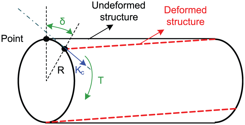
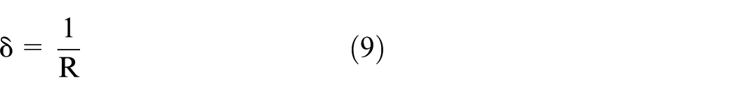
To obtain the total rotational stiffness of the contact surface for the key connection, the total rotational stiffness of two springs in series and in parallel were analyzed, as shown in Figure 6.

Sketch of springs in series and in parallel.
Springs 1 and 2 are in series, while springs

From this, the total rotational stiffness at point
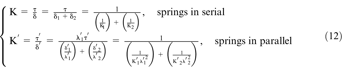
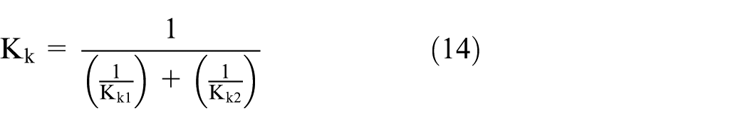
By extending this to n springs in series or parallel, which are general to other kinds of connections, the total stiffness can be defined as

Since the torsional stiffness of the two contact surfaces for the key connection (Figure 4) are in parallel, the total torsional stiffness can be modeled as
Torsional stiffness for a bolt connection
In a bolt connection, the pre-tightening forces of the bolts are applied to the contact surface connecting the two parts, and their values greatly affect the contact quality. Modeling the relationship between the pre-tightening forces and rotational stiffness is important in guiding the bolt tightening of each joint.
With the transmission system of an industrial robotic joint, a bolt connection is always adopted to connect the reducer with the robotic body. For most reducers, the contact surface of the bolt connection is a looped region as shown in Figure 7, where

Sketch of a bolt connection.
For this contact surface, the total normal force is determined by the pre-tightening force

Substituting the normal force

where
Torsional stiffness for a pin connection
In some robotic joints, pins are used to connect two components. A sketch of this type of connection is shown in Figure 8, where

Sketch of a pin connection.
With this connection, several pins with external threads are used to apply pre-tightening forces on the cylindrical surface of the shaft leading to contacts. In the actual assembly work, the preloads of all pins in one pin connection are set to be the same to avoid the instability led by the unevenly distributed force on the contact surface. For each contact surface, the normal and tangential stiffness can be calculated by substituting the normal force
Joint stiffness for ER3A-C60 robot
In the simulation analysis, the ER3A-C60 robot is used as the research object. For its first two joints, the harmonic reducer matches with the motor in structure, and they are assembled with a single key. In joints 3, 4, and 5, the synchronous pulley also matches with the motor; therefore, only one key connection exists between the connected components. However, in the sixth joint, a connecting shaft is used due to the mismatch between the reducer and the motor, such that the local assembly consists of two key connections. In addition, a shaft connects the synchronous pulley and the harmonic reducer so there are two connections between them. The harmonic reducers are connected to the robotic body using the bolts. A sketch of the robotic model, where the reducers and the contacts are represented as the torsional springs, is presented in Figure 9.

Sketch of the model showing each joint and its connection types.
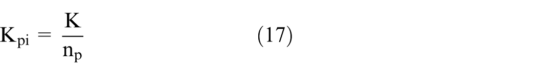
The problem of calculating torsional stiffness for each joint is broken down into several distinct problems of computing the torsional stiffness for each contact and reducer. The torsional stiffness of each contact can be calculated based on the model presented in section “.” The reducer is a complex structure and has been standardized by some manufacturing enterprises, such as Leaderdrive, an enterprise of China. The rotational stiffness would be calculated according to the stiffness characteristic map obtained in the experiment and given in the product manual, since the harmonic reducers of the ER3A-C60 robot are made in the Leaderdrive and meet the national standard. From the PRC national standard GB/T 30819-2014, the information and stiffness values of the harmonic drivers are listed in Table 1, where
The product models of harmonic reducers for all joints and their critical parameters.
Then, according to the output torque of each joint, a value of torsional stiffness for the corresponding reducer can be determined. The process of obtaining the joint stiffness is shown in Figure 10 and the parameters used are listed in Tables 1–6.

Flowchart showing the process of obtaining joint stiffness.
The values of the main parameters for belt connections.

The processing information of the contacts and the parameters used in fractal theory.

The values of parameters for key connections.

The values of parameters for bolt connections.

The values of parameters for pin connection.

Based on that, the joint stiffness of the ER3A-C60 robot can be calculated when the output torque of each joint is known. To verify the effectiveness of the presented model, the results are compared with those based on the model without considering the contacts.6–8 Besides that, to reveal the influence of the output torque on the joint stiffness, the ratio
The maximum values of the output torque for each joint.

Results and discussion
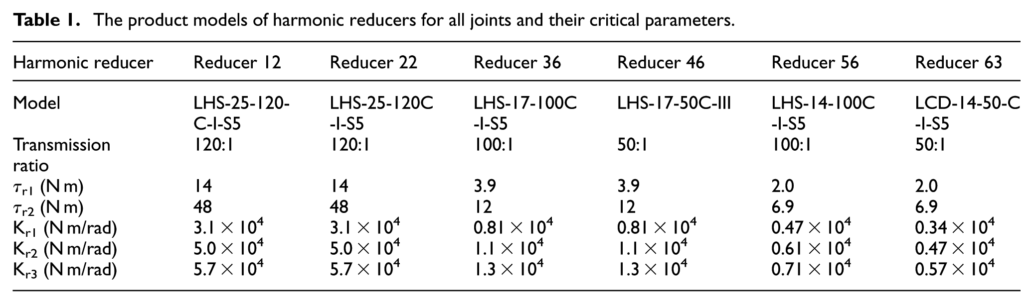
The previous studies,10–12 which proposed a technique of calculating joint stiffness without considering the contacts, show that the predicted joint stiffness is always larger than the experimental one due to the ignorance of the effects of some detailed structure, like contacts. To show the significance of the presented model, we define
Comparison of the ratios
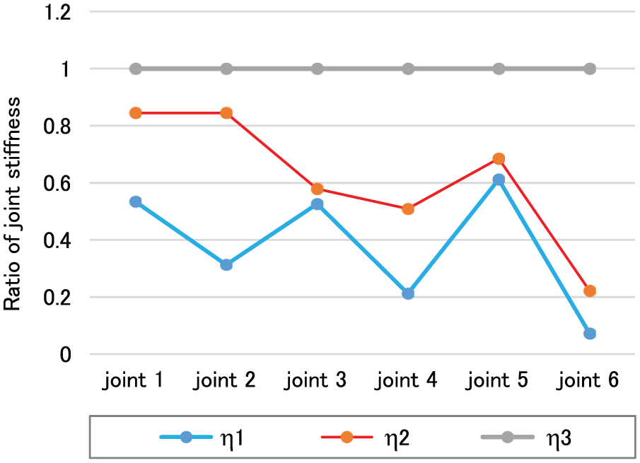
Figure 12 shows the variation of the joint stiffness for each joint with the increasing ratio of the output torques and the comparison of the results based on the previous and the presented models. The results indicate that the joint stiffness based on the presented model, which considers the contacts, is smaller than that based on the previous model, and as the joint output torque becomes closer to zero, the difference between the joint stiffness based on the two methods is larger. Moreover, the stiffness of all joints based on the presented model change nonlinearly due to the nonlinear relationship between contact stiffness and normal force, which is calculated using the torque value of each joint. The sudden changes in the joint stiffness curves are caused by variation in the reducer stiffness values as the output torque of the reducer is within different ranges. The figure also shows that the joint stiffness increases dramatically when the torque ratio is close to zero and tends to vary gently with increasing torque ratio, which implies that the too small output torques would lead to the large dynamic error of the end effector due to the high joint flexibility.
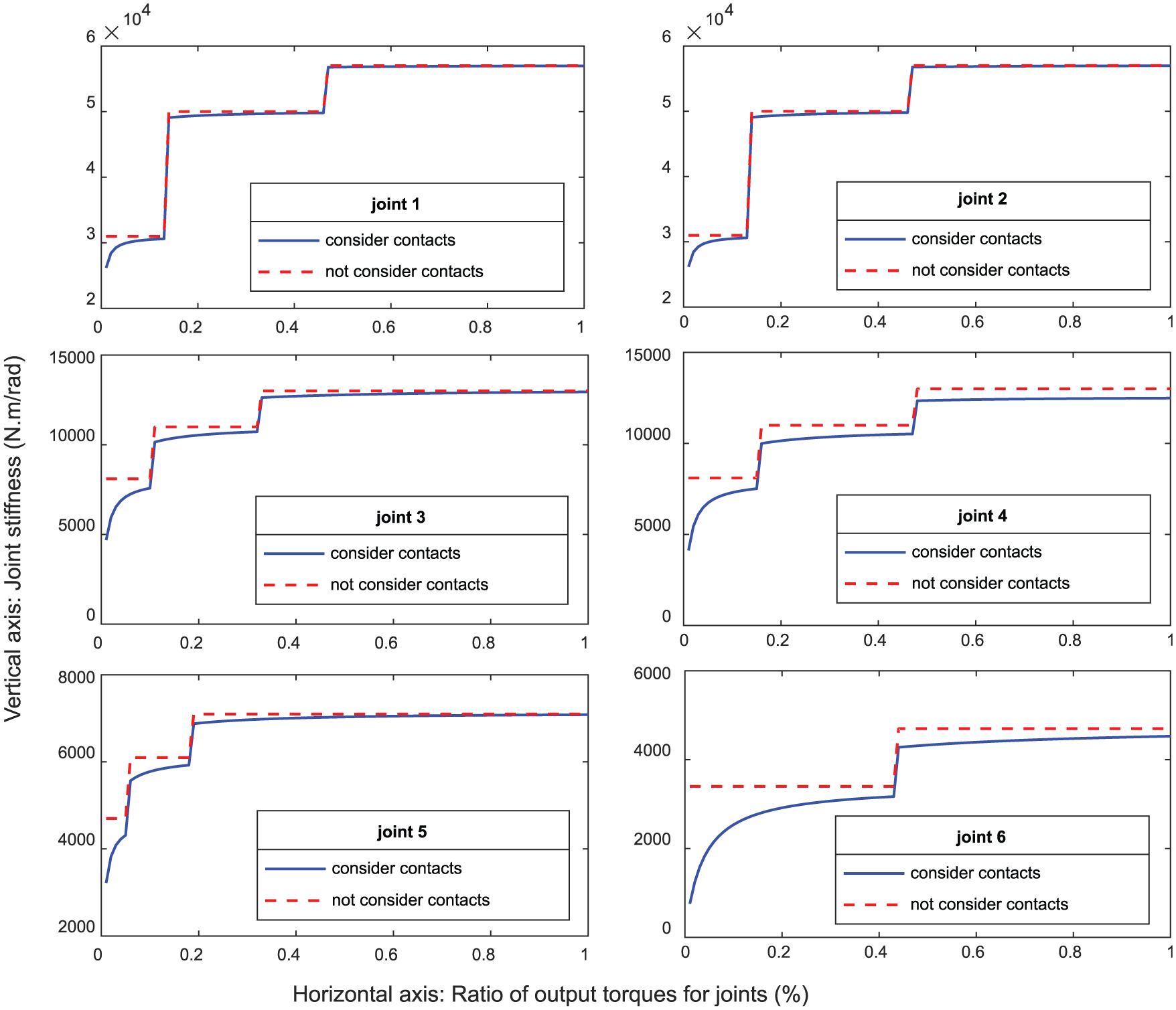
Variation of joint stiffness with output torque for each joint.
Since the input torques are calculated based on the kinematic parameters (including the angular displacement, velocity, and acceleration) of all joints using the dynamic equations, 29 the joint stiffness would be affected largely by these parameters. This effect would be used to improve the motion accuracy by maximizing the joint stiffness through the trajectory optimization. Furthermore, the surface pressures for the bolt and pin connections are determined by the pre-tightening forces of the bolts and pins. According to Zhao et al., 30 the contact torsional stiffness and the surface pressure have the positive correlation, and the stiffness would be improved very slowly when the pressure increases to a certain level. This relation means that although the increase of the pre-tightening force can improve the joint stiffness, the pre-tightening forces should be optimized according to the actual requirements of the motion accuracy and the properties of the bolts or pins, which can guide the robotic assembly task.
Conclusion
In this work, a technique of modeling the joint stiffness for industrial robots with rotational joints is presented by considering the influence of the contacts. In this technique, the torsional stiffness of the contacts for the connections, which commonly exist in the rotational joint systems, were modeled. Through modeling the equivalent stiffness, the stiffness of the joints for an industrial robot, ER3A-C60, were calculated and analyzed. The results indicate that the estimated stiffness of all joints based on the previous model without considering the contacts are larger than those based on the presented model, which are much closer to the actual values. The comparison can prove that the presented model is more accurate than the previous one and is reliable in the calculation of joint stiffness. For the presented results, the joint stiffness of all joints change nonlinearly with the increasing torque ratio. Moreover, as the torque is closer to zero, the decrease of the joint stiffness is more dramatic. The analysis provides a foundation for improving the dynamic characteristics of the rotational joints while planning trajectory for the end effector.
In the future work, the stiffness of all joints in multiple robotic systems will be obtained using the experimental identification method and compared with that calculated using the presented model to further show the reliability of this model directly. Moreover, this model will be used to calculate the synthesis error of the robotic end effector that is caused by the joint flexibility and geometric errors by combining the dynamic analysis of the industrial robots, and then show its correctness by comparing the end effector motion errors obtained using laser tracker and the presented stiffness model.
Footnotes
Appendix 1
Handling Editor: ZW Zhong
Declaration of conflicting interests
The author(s) declared no potential conflicts of interest with respect to the research, authorship, and/or publication of this article.
Funding
The author(s) disclosed receipt of the following financial supportfor the research, authorship, and/or publication of this article: This research was supported by Beijing Municipal Science and Technology Commission (No. D1711040 0590000), National Natural Science Foundation (No. 5157 5009), and Jing-Hua Talents Project of Beijing University of Technology.