
Abstract
A novel morphing unmanned aerial vehicle with tandem-wing configuration could fold into a tubular catapult and deploy the four airfoils after launching. Because of the rapid deploying process, the aerodynamic characteristics will become largely different. Numerically investigating the aerodynamic characteristics at low Reynolds numbers (Re < 106) is of great significance for control-stability analysis, control laws design, and overall design. By comparing the numerical simulation results of the different airfoils arrangements, the authors have found that model A is more appropriate for folding configuration and model B will generate more obvious unbalanced downwash flow influence. The lift, drag, and hinge moment of the canard and wing vary significantly during the deploying process. This phenomenon is due to the aerodynamic interference and mutual coupling between the canard and wing. Moreover, the rapider deformation rate will cause higher variable quantity of the unsteady aerodynamic characteristics. The additional movement plays a dominant role in the variable quantity compared with the hysteresis effect. The authors have also tested the catapult launching under folded condition and unfolded condition. And the experimental results coincide better with the simulation results.
Keywords
Introduction
Unmanned aerial vehicle (UAV) systems have been widely employed in military and civil fields across the globe in recent years. 1 Various kinds of UAV systems emerge in endlessly as the technology improves, especially of morphing aircrafts which can manipulate their external shape to replace conventional control surfaces and to achieve better flight performance. 2 However, as adaptively altering aerodynamic configuration of the morphing aircrafts, its aerodynamic parameters change dramatically, and that will cause the system to be complicated and uncertainty. Therefore, there are more challenging to researchers on aerodynamics of morphing UAVs and to manipulate them than traditional aircrafts.3–5
Among the various kinds of morphing vehicles, there are certain types of UAV with folded airfoils that could launch from a tubular catapult and deploy the airfoils while in free flight. 6 The folded technology can reduce the space usage for easy storage and transportation and brief fuselage structure without undercarriage can reduce the vehicle weight effectively. On the other hand, the catapult approach has higher security, less wind influence, faster take-off speed, and better launch stability than other launching modes; it also has no need of take-off runway and can be launched from other aircraft or underwater. 7 During the catapult launching process, rapid transformations in aerodynamics and structure of the morphing UAV may have a significant influence on stability and maneuverability. A new approach for computational fluid dynamics based on aeroelastic simulation was presented by Selitrennik et al., 8 and their study demonstrated that transient elastic deformations and aerodynamic loads have significant effects on rapidly morphing UAV.
The requirement that the vehicle needs to be folded into the allowed space of a tube launcher needs the wing aera large as far as possible, so the tandem-wing layout is a good choice. 9 Behrbohm 10 discovered the advantages of tandem-wing layout and the research on tandem-wing aircraft had attracted more attention. Broering and colleagues11,12 from University of Louisville investigated the influence of wing spacing on the tandem-wing aerodynamics by the numerical calculation. And English et al. 13 tested the performance of tandem-wing micro air vehicles at full scale in wind tunnel environment. Ahmed and Kohama found from the experiments for tandem-wing configuration that the shorter distance between the canard and wing, the stronger interference effect between the wake of canard and wing. And when the spacing between the canard and wing increased, the serious pitching instability was shown. 14 Laitone and Butler analyzed the influence of downwash flow on the induced drag of canard–wing combinations using the Prandtl theory. And they found that if the span of rearward surface is greater than forward surface, induced thrust contribution to the total induced drag is significant.15,16
The current research for the tandem-wing mainly focuses on two aspects: one is the superiority compared with corresponding single wing system and other is how to improve the aerodynamics through controlling interference effect of wake vortex between canard and wing. Rival et al.’s 17 study showed that tandem-wing systems had better fuel efficiency and less resistance than the single configuration. Selberg and Rhodes had compared two types of dual-wing configuration aircrafts with corresponding single-wing aircraft in experiments to research the advantages and disadvantages of multiple-wing systems. Their study showed that dual-wing configuration has better cruise performance, lower fuel consumption, lighter engine weights, and lighter wing weights than the corresponding single-wing configuration. 18 Wind tunnel experiments for tandem-wing configurations with two identical Wortmann FX63-137 airfoils were carried out by Scharpf and Mueller. The flow visualization and measurement results showed that for several configurations, the lift-to-drag ratio increased obviously with the decrease of total drag and the increase of total lift. 19
In our study, we proposed a novel tandem-wing UAV which could be catapult launched and deployed in free flight. Moreover, a novel idea that the four airfoils sweep angles change for roll control and pitch control rather than traditional aileron is applied in flight control. For the novel idea, the morphing progress is based on catapult launching to acquire sufficient take-off speed, so the large acceleration during the catapult launching process may cause the aerodynamics around the UAV vary greatly, especially with the rapid rotation angle changes of airfoil. In this study, we mainly concentrate on researching the aerodynamic effects on lift and drag characteristics during rapid deploying process of tandem-wing UAV, and the effects under different catapult launched conditions should also be paid attention to. Meanwhile, due to small dimension, the tandem-wing UAV in our studies will fly at low Reynolds numbers environment (Re < 106). It is well known that for low Reynolds numbers incompressible flows, the airfoil boundary layer mostly locates in laminar flow state and becomes prone to separate under the action of adverse pressure gradient. 20 This separation bubbles follow quick transition from laminar to turbulent flow and may lead to losses of aerodynamics even stalling. 21 GQ Zhang has investigated numerically the unsteady aerodynamics effects for a catapult launched tandem-wing UAV which has two morphing stages at low Reynolds numbers environment. Because of the rapid rotation of the canards and wings, unsteady aerodynamics have significantly effects including the hinge moment and lift and drag coefficients. These phenomena were confirmed caused by vortex interactions between the canards and wings. 22
Compared with the morphing tandem-wing UAV model of G.Q. Zhang, the model we discussed here only has one morphing stage and has less hinges which will reduce damping of the deformation process and make the structure simple and stable. Because of massive acceleration while catapult launching, the separation bubble would be more complicated and the airfoils may suffer larger aerodynamic loading. Two types of tandem-wing configurations will be simulated numerically using computational fluid dynamics (CFD) method. The UAV catapult launched under unfolded and folded conditions will be simulated numerically and experiment, respectively. And the corresponding results were presented and discussed.
Aircraft configuration and numerical simulation method
Aircraft configuration
The canards and wings of the tandem-wing aircraft have the same size to improve the load capacity and it is easy to maintain longitudinal balance. In order to reduce the effect of downwash caused by the canard, layout that the wing is located above the canard was chosen. Because high curvature of wings may cause longitudinal instability in catapult launching process and the folding way needs, low curvature airfoil Ritz 3-30-11 is chosen as the canards and wings of the tandem-wing UAV. As shown in Figure 1(a)–(c), after catapult launching, the morphing aircraft deploys with the canards rotating forward by 90°, the wings rotating backward by 90°, and vertical tails rotating upward by 65°.
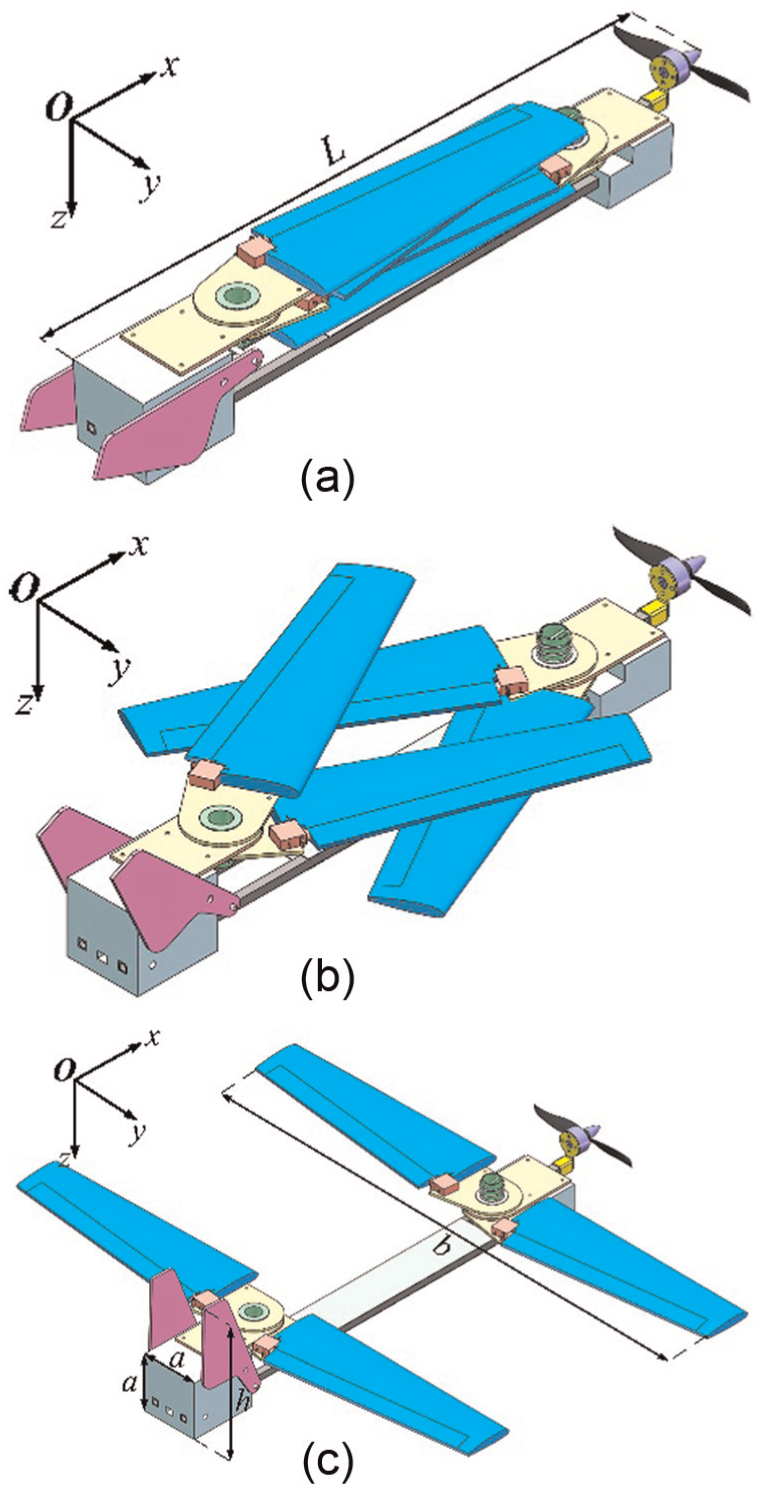
Schematic of the folding process for a catapult launched UAV: (a) folded condition, (b) morphing stage, and (c) unfolded condition.
Three main factors affect the performance of the tandem-wing system: stagger St, the horizontal separation of the canard and wing; gap G, the vertical distance between the canard and wing; decalage D, the relative angle between the canard and wing. 18 The parameter definitions of the tandem-wing system are shown in Figure 2. Considering the deformation, the canard and wing keep a parallel state, so the decalage D remains constant; c represents chord of the airfoil, α represents angle of attack (AOA), and v represents freestream velocity.
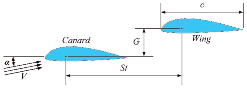
Schematic of parameter definition for the tandem-wing system.
The viscous drag decreases significantly with appropriate gap and stagger. 23 Because the wing is located above the canard, both St and G are positive. Smaller St will cause stronger interaction between the canard and wing stronger and larger St may cause aerodynamic coupling influences of the tandem-wing have no positive effects. 24 To prevent interference of the folding structure, St must be large enough to fit the wing span and 300 mm is suitable size.
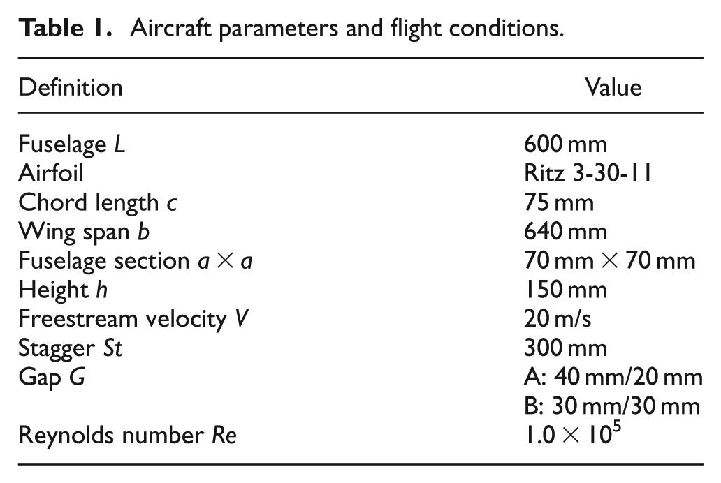
In folded condition, the four airfoils of the UAV overlap together along the Z-axis direction, the layout of tandem-wing UAV in unfolded condition is asymmetric, and there are two types of airfoil configurations as shown in Figure 3. Because there is a vertical distance of one airfoil thickness between the canards and between the wings, for model A the G of left side and right side are both 30 mm, for model B the G of left side is 40 mm and right side is 20 mm. The aircraft parameters and flight conditions are shown in Table 1. The freestream velocity V is 20 m/s, corresponding to a Reynolds number Re of 1.0 × 10⁵ based on the airfoil chord c.

Two types of airfoil configurations: (a) model A and (b) model B.
Aircraft parameters and flight conditions.
Numerical simulation method
The numerical simulation is conducted using CFD commercial software FLUENT 16.0 and based on the finite volume numerical method. Dynamic grid technology is used to simulate the dynamic rotation of the canards and wings.
According to Newton’s Second Law and the relationship between stress and strain, the general form of Navier–Stokes equation for compressible flow can be written as

where
The freestream Mach number is approximately equal to 0.06, so that the incompressible flow was considered. For incompressible fluid, the density is constant

The continuity equation of fluid motion can be presented using the following expression

Combination expansion (1), (2), and (3), the general form of Navier–Stokes equation for incompressible flow can be written as

We have adopted the Spalart–Allmaras turbulence model for the CFD simulation. Spalart–Allmaras model which is based on the transport equation of a pseudo-viscosity has aerodynamic characteristics of low Reynolds number and is specially applied to aviation field involving bound wall flow. For the boundary layer under the effect of adverse pressure gradient, the model can give a good simulation results. 25
The computational domain is a bound box which size is 60 times of the chord. In order to choose appropriate grid number, we have simulated the lift-to-drag ratio of the tandem-wing aircraft at AOA of 4° for five different grid numbers and the result is shown in Figure 4. The grid numbers are 1.38 × 10⁶, 1.77 × 10⁶, 2.03 × 10⁶, 2.28 × 10⁶, and 2.64 × 10⁶, respectively. Figure 4 shows that the lift-to-drag ratio is more accurate with the increase of grid number and the variation is lower than 0.09% when the grid number is over 2.28 × 10⁶. In order to guarantee accuracy and reduce calculated amount of the CFD simulation, the gird number 2.28 × 10⁶ is adopted for the subsequent computation.

The effect of grid number on lift-to-drag ratio.
The computation domain and the mesh are shown in Figure 5. The rotating propeller can generate obvious aerodynamic interference on the airfoils during the morphing progress; as a result, it is unable to accurately analyze the effect of the rapid deformation, so the propeller is not considered in the mesh temporarily. 26 Size function is used to refine the mesh, smooth which can reconfigure the nodes and swap which can modify the connectivity of units are used to improve the mesh quality. The flow material is ideal gas and the numerical simulation adopts the pressure far field boundary at flow velocity of 20 m/s corresponding to a Reynolds number of 1.0 × 10⁵.
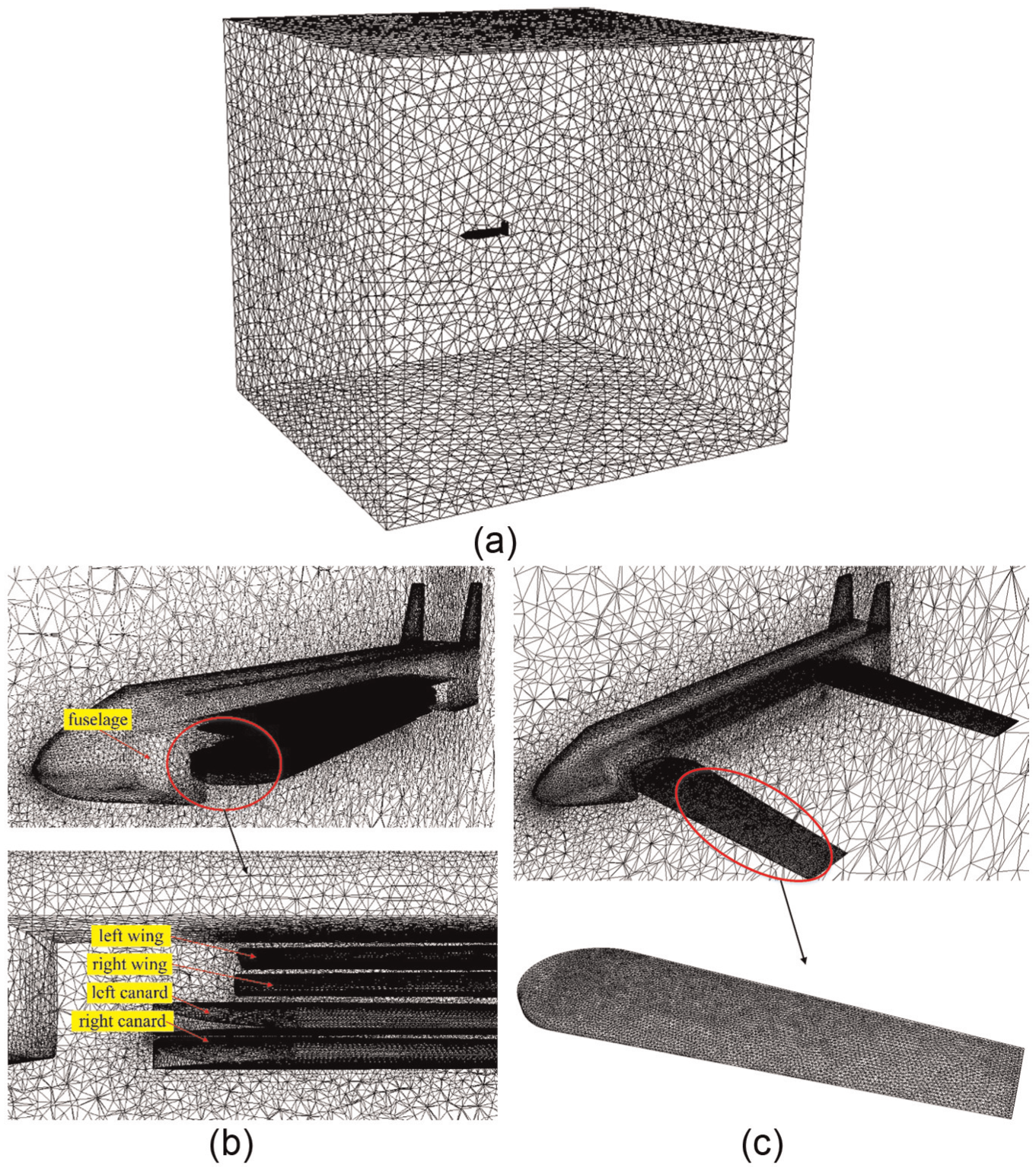
The computation domain and the mesh: (a) computational domain, (b) the mesh of folded configuration, and (c) the mesh of unfolded configuration.
Results and discussion
CFD method validation
To verify the reliability of the CFD method, we have simulated the circle flow fields using Spalart–Allmaras turbulent model for single wing and tandem-wing case, respectively, and the results were compared with the wind tunnel experimental data that were measured by R Jones et al. 27 Flat-plate rectangular wing and the same geometrical parameter that used in the wind-tunnel experiment were chosen. The lift and drag characteristics at various AOAs are shown in Figure 6. Compared the CFD results with the experimental measurements, we can know that the lift coefficients for single wing and tandem-wing coincide better with the measured values and drag coefficients have the maximum difference within 8% but the variation trends are similar. And the stall angle of tandem-wing configuration is delayed significantly compared with single wing configuration. The CFD approach has an excellent accuracy, considering the precision of measurement method and the simulation errors.
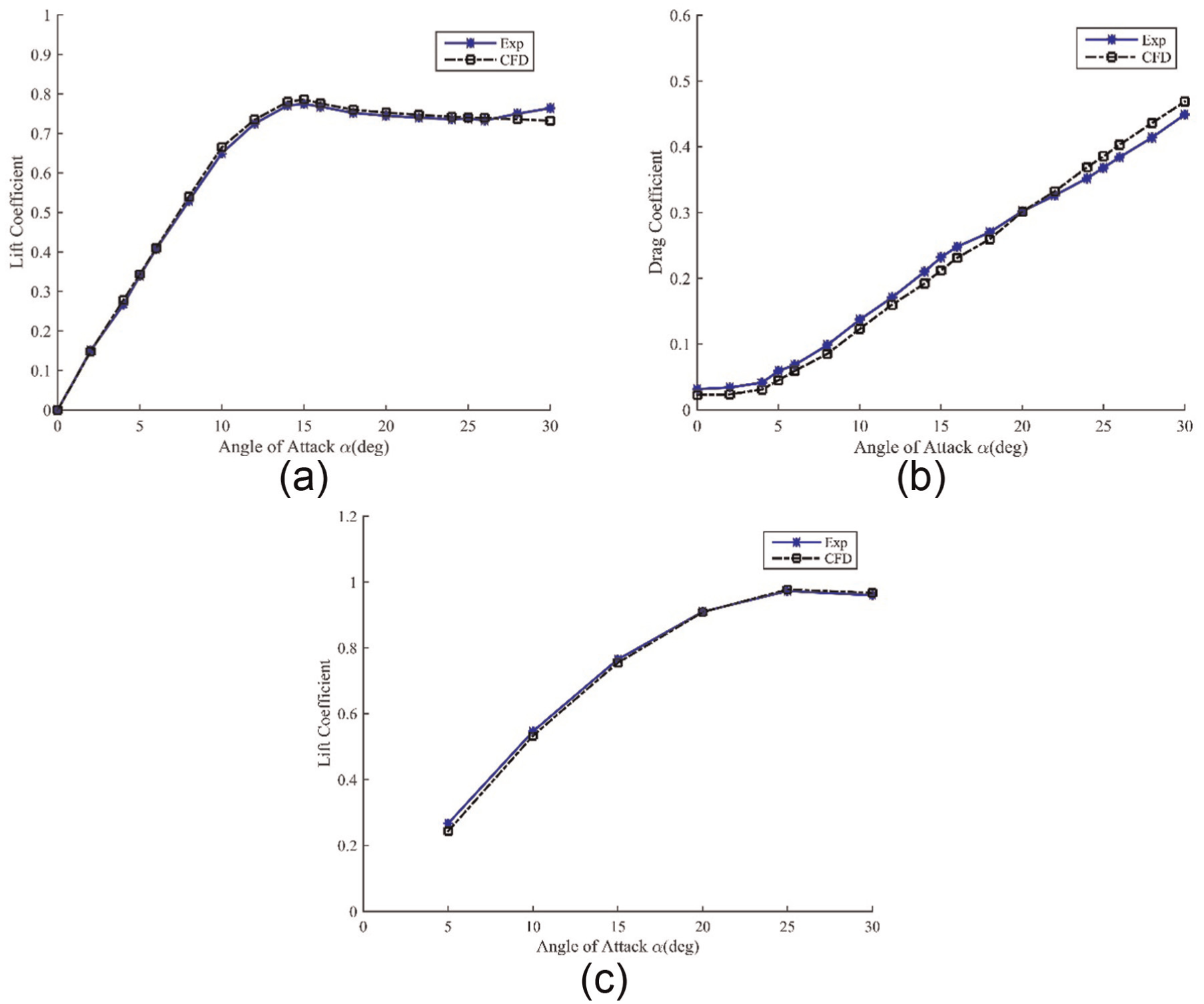
CFD results compared with wind tunnel experiment data: (a) lift coefficients for single wing, (b) drag coefficients for single wing, and (c) lift coefficients for tandem-wing.
Aerodynamic characteristics of the different folding models
The numerical research on aerodynamic characteristics varying with AOA of the two models is presented under the same boundary conditions. As shown in Figure 7(a) and (b), the lift and drag curves of two models are almost overlapping. It is clear that small difference of gap has a negligible effect on the lift and drag characteristics of the whole aircraft. In contrast, the differences of roll moment about body axis between model A and model B are distinct as shown in Figure 7(c). The roll moment of model A (MA) keeps negative and has a maximum of −0.014 N·m, minus sign here indicates the direction. It changes smoothly and shows the similar trend as the lift characteristics. However, the corresponding roll moment of model B (MB) varies a lot. When AOA is less than 4°, roll moment is negative and changes in the vicinity of zero. If AOA is greater than 4°, the roll moment reverses direction and reaches the maximum of 0.046 N·m at AOA of 16°, with the further increase in AOA the moment changes to the opposite deflection rapidly until near zero. This phenomenon may mainly attribute to the asymmetric airfoils arrangement which has caused unbalanced downwash flow influence.
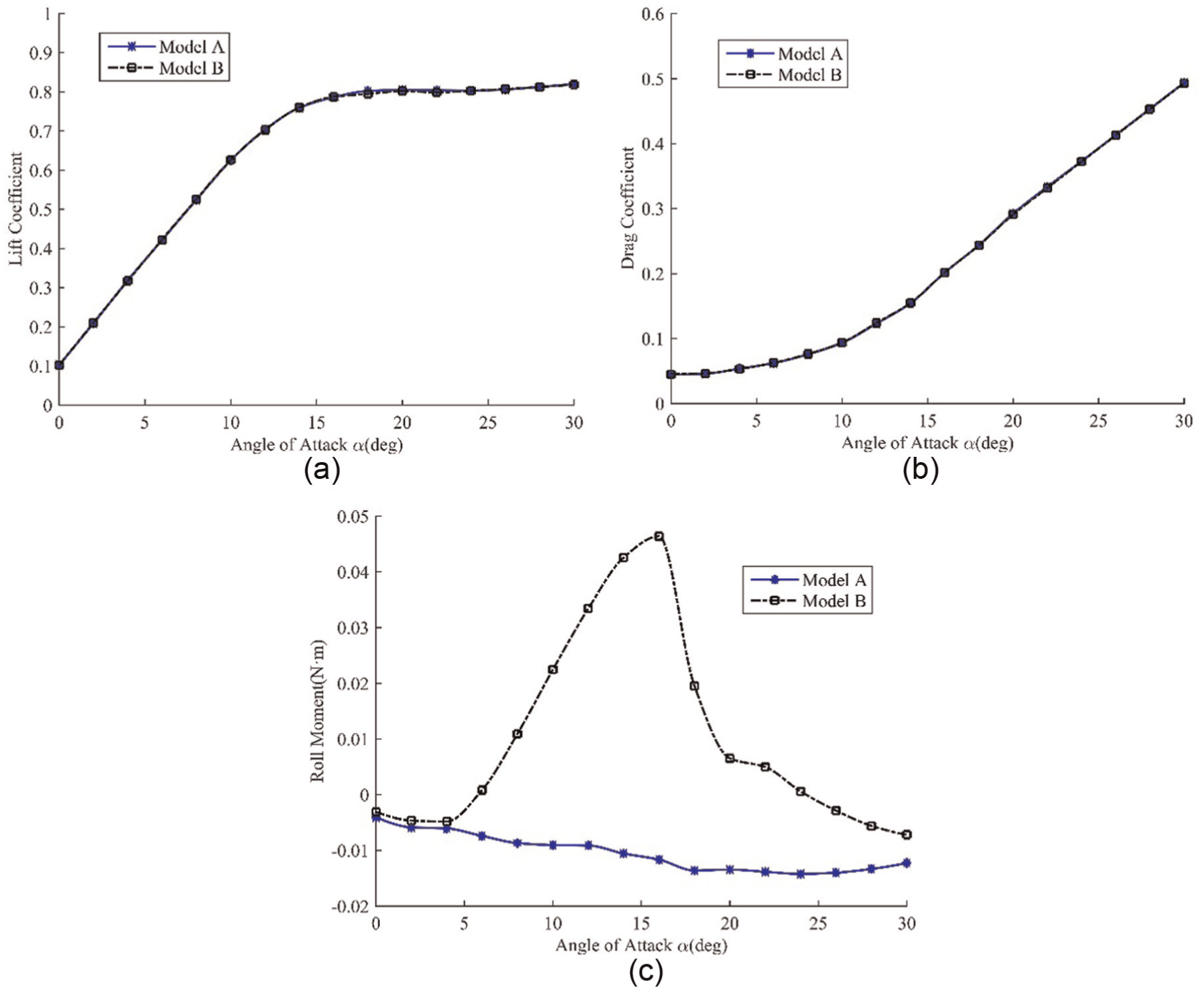
Comparison of the aerodynamic characteristics varying with α for the two folding models: (a) lift coefficients, (b) drag coefficients, and (c) roll moment.
The airflow will slant downward after flowing past the canard and then come into being downwash flow. The effect can create a downwash angle ε as shown in Figure 8(a), thereby reducing the effective AOA of the wing. The downwash effects on the left wing and right wing shown in Figure 8 are without distinction and this is due to the identical gaps of left side and right side, so the generation of roll moment is irrelevant to the size of gap.
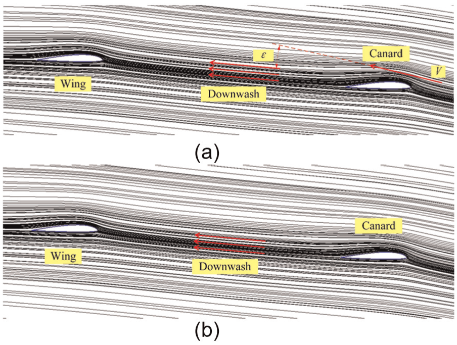
Effect of downwash on streamlines for model A at α = 8°: (a) left side and (b) right side.
Comparison of the static pressure distribution around the left and right wing surfaces of model A along spanwise at different AOAs is shown in Figure 9. The static pressure around lower surfaces (higher pressure area) is almost coincident at all AOAs when the static pressure around upper surface (lower pressure area) of left wing is greater than the right wing. Due to the constant pressure difference, the lift of left side is greater than of right side, thereby creating constant negative roll moment. Moreover, the pressure difference increases gradually in the direction to the wing root and this phenomenon is due to fact that the left airfoils and right airfoils have a dislocation of one airfoil thickness that induces the asymmetry of airflow influences. The closer to fuselage the region is, the more obvious the difference becomes.

Comparison of the static pressure on the wings for model A at different angles of attack: (a) α = 4°, (b) α = 10°, (c) α = 16°, and (d) α = 22°.
Figure 10 shows the static pressure distribution around the left and right wing surfaces of model B along spanwise at different AOAs. The static pressure range at different angles of attack compared with the range of model A has no obvious change; however, the pressure distribution around lower surfaces and upper surfaces shows significant difference with the change of AOA as shown in Figure 10. When α = 4°, by observing the streamlines shown in Figure 11(a) we have found, the right wing suffers more influence of downwash flow generated by the canard than the left wing, so the static pressure of left side is larger than of the right side. Nevertheless, because of small AOA, the influence difference is not obvious and small roll moment comes about. When α = 10°, the left wing is completely located in the downwash flow but the right wing is partly located in the downwash flow as shown in Figure 11(b); in other words, the effective AOA of left wing is less than that of right wing. As a result, the static pressure curve of left wing is surrounded by the curve of right wing as shown in Figure 10(b). Therefore, the static pressure of left side is less than the right side and the unbalance of pressure produces significant positive roll moment. With α increase to 16°, pressure difference between left wing and right wing becomes more evident as shown in Figure 10(c) and the corresponding roll moment gets larger, too. As shown in Figure 11(c), at α = 16°, the canard creates a clear leading edge vortex on the upper surface and the influence of downwash destroys the vortex formation of the wing. With the increase of α, the downwash flow region is more and more far away from the wing. When α = 22°, the downwash phenomenon becomes stronger than the other conditions, but the downwash flow has almost no influence on the wing whether left side or right side due to the large AOA, and the wing has also created a leading edge vortex on the upper surface as shown in Figure 11(d). Therefore, the static pressure curves on the upper surface of the wings vary in an irregular way as shown in Figure 10(d) and the corresponding roll moment is also nearly zero. In conclusion, the downwash flow influence on the wings of model B varies greatly with the increase of AOA and the results shown in Figure 10 are closely related with the roll moment change.

Comparison of the static pressure on the wings for model B at different angles of attack: (a) α = 4°, (b) α = 10°, (c) α = 16°, and (d) α = 22°.
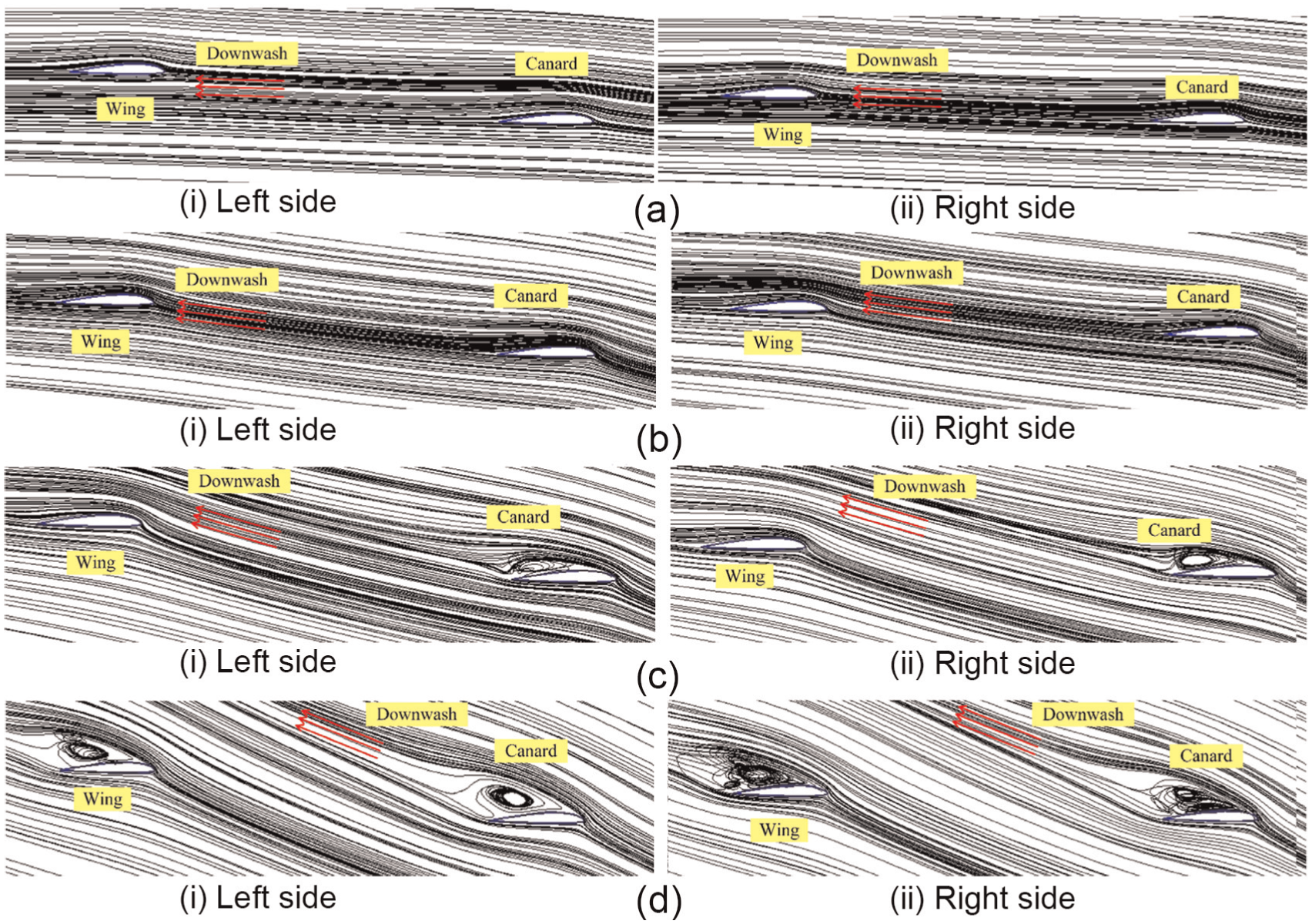
Streamlines of model B in chord length section: (a) α = 4°, (b) α = 10°, (c) α = 16°, and (d) α = 22°.
The unbalanced roll moment generated by model A shows the similar trend as the lift of model A and direction is constant, in addition, the maximum value is only 30% of the moment generated by model B. So we could use the torque generated by the rotating motion of propeller compensates the roll moment, making the aircraft keep lateral stability. For model B, by reason of the asymmetric gap, the wings of the left side and right side at different AOAs affected by the downwash flow have obvious distinction, so that the roll moment varies drastically and is hard to manipulate. In consequence, model A is more appropriate for folding configuration.
Unsteady aerodynamic effects in deploying process
After catapult launching, the canards and the wings of the morphing UAV are rotating forward and backward by 90° to their final orientations, respectively. Aerodynamic characteristics variation will be studied in this process. The morphing condition in deformation cycle of 0.05, 0.1, and 0.2 s have been simulated at AOA of 4° and compared with the results of the final steady condition, respectively, for studying the effects of deformation rate. The vertical tail motion is temporarily taken no account.
Figure 12 shows the lift and drag variation of the canard and wing compared with the steady-state values (SSV) which are the aerodynamic characteristics of the morphing UAV under unfolded condition, and it shows clearly that the rapidly morphing has created effects on the unsteady aerodynamics of the whole UAV to a certain extent during the deploying process. With the increase of rotation angle, the lift and drag of the canard and wing are on the rise significantly. It can be explained that during their rapidly rotating from parallel to the body axis toward the final positions, the projection areas perpendicular to the airflow and surface areas increase rapidly. However, canard lift (LC) shows obvious nonlinear characteristics and reaches a maximum near the rotation angle of 72° as shown in Figure 12(a). And wing lift (LW) shown in Figure 12(c) experiences a gentle increasing from 1% to 10% when the rotation angle is less than 55° and then a sharp increasing from 10% to more than 55%. On one hand, it is due to that during rotating motion, the direction of the airfoils relative to airflow keeps changing all the time and the cross section shape of the airfoils which parallel to the UAV symmetry plane is quite irregular. 28 On the other hand, the aerodynamic interference and mutual coupling between the canard and wing have created influence on the aerodynamic characteristics within deploying process.

Lift and drag of the canard and wing in deploying process: (a) canard lift, (b) canard drag, (c) wing lift, and (d) wing drag.
The projection areas of the canard and wing along the Z-axis direction will overlap some area during the initial process of morphing, and with the downwash vortex shedding there will form a low pressure region between the overlapping sections. As shown in Figure 13(a), part of the wing is located above the low pressure region generated by the canard at rotation angle of 45° as a result LW increases slowly. With the rotation angle increasing, overlapping sections separate gradually and the wing moves away from the low pressure area as shown in Figure 13(b), then LW increases swiftly. In addition, the counteractive of the wing will make the low pressure area above the canard stronger and the interference of the wing induces a weak high pressure area at trailing-edge of the canard as shown in Figure 13(c) and (d). As a result of these effects, LC shows the nonlinear characteristics.
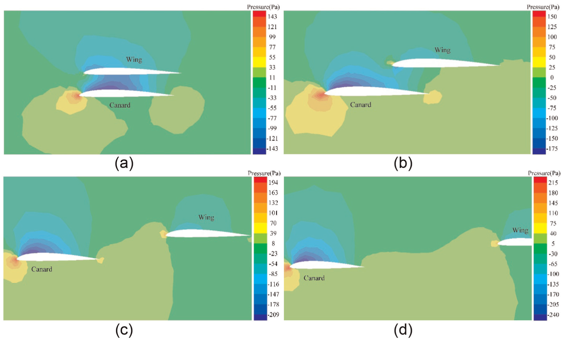
Contour of static pressure at different rotation angles: (a) rotation angle of 45°, (b) rotation angle of 54°, (c) rotation angle of 63°, and (d) rotation angle of 72°.
The lift and drag characteristics at the three different deformation rates show the similar trend according to the simulation results. Moreover, if the time of deformation is 0.05 s, the corresponding LC and canard drag (DC) show higher increase than the condition of 0.1 and 0.2 s. At rotation angle of 90°, LC has increased in particular by about 42%, 23%, and 13%, respectively, and DC has increased by about 50%, 26%, and 14%, respectively. In contrast, if the time of deformation is 0.05 s, the corresponding LW and wing drag (DW) show higher decrement than the conditions of 0.1 and 0.2 s.LW has decreased by about 45%, 27%, and 19%, respectively; DW has decreased by about 25%, 11%, and 8%, respectively. This phenomenon shows that deformation rate has great influence on the unsteady aerodynamic characteristics. In general, due to inertia effect flow field around the rotating airfoils would generate hysteresis effect which could cause the aerodynamic forces to indicate a delay variation relative to SSV, 29 whereas the hysteresis effect is opposite to the results shown in Figure 12. However, the relative speed between the airfoils and freestream will keep changing during the transformation process and that is equivalent to increasing an additional speed on the freestream speed, thereby changing the aerodynamic forces of the airfoils accordingly. The effected on the aerodynamic forces of this additional movement can be presented as

where

where l is wing length of 0.3 m and
The value of
For the whole aircraft, the lift and drag characteristics during deploying process are shown in Figure 14. Overall lift (L) increases near linearly and overall drag (D) increases nonlinearly. Because the aerodynamic forces of canard increases and the aerodynamic forces of wing decreases, these two effects compensate each other, leading to L and D change slightly relative to SSV. Similar, the canard and the wing under the influence of the additional movement, the rapider deformation rate makes the aerodynamic forces vary more greatly, which illustrates the aerodynamic forces of canard play a dominant part during deploying process.

(a) Lift and (b) drag of the aircraft in deploying process.
The canard and the wing will generate hinge moment around the rotation axis during deploying process shown in Figure 15. With the increase of rotation angle, canard hinge moment (MC) and wing hinge moment (MW) show the similar variation trend with DC and DW, respectively. However, MC shows an incremental linear trend and MW shows obvious nonlinear characteristics. We should not ignore the aerodynamic interference between the canard and the wing and the downwash effect generated by the canard during the deploying process. On the other hand, the cross section shape of the wing tip which is parallel to the UAV symmetry plane transforms anomalously during backward rotating motion, heightening the differential pressure of wing tip. With these effects in mind, we can clearly see nonlinear characteristics of MW as shown in Figure 15(b). Moreover, the shorter the deformation cycle is, the more effect that is on MC and MW, the increments are about 87%, 50%, and 28% with respect to SSV, respectively, and the decrements are about 25%, 11%, and 7% with respect to SSV, respectively.
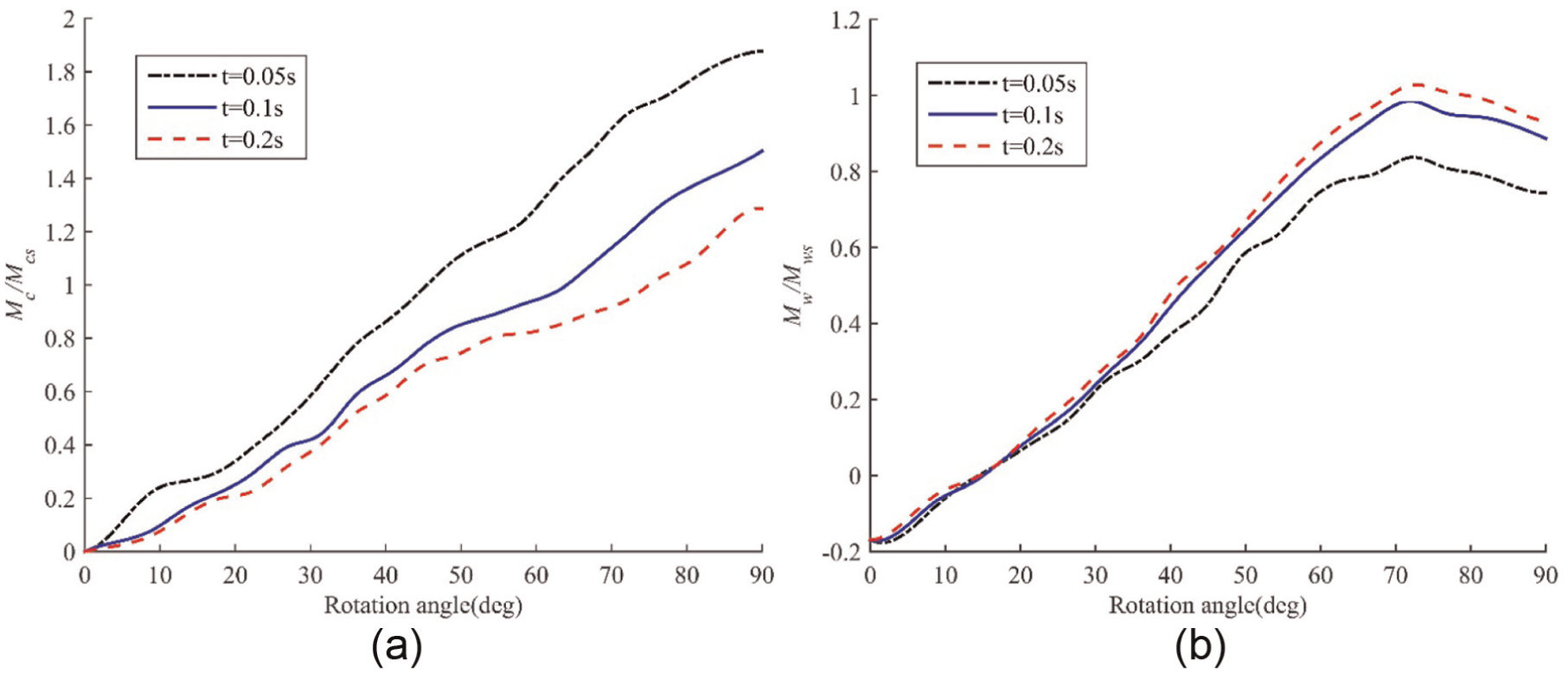
Hinge moment of the (a) canard and (b) wing in deploying process.
Catapult launch under folded condition and unfolded condition
The aircraft could be catapult launched either under folded condition or under unfolded condition; the aerodynamic forces under the two conditions are completely different. As shown in Figure 16, the lift and drag of the aircraft catapult launched under folded condition both increase linearly during the deploying process and then reach SSV near the time of 0.14 s. This is due to the hysteresis effect which is generated by the fluid inertia, thereby leading to delay variation of the aerodynamic forces relative to SSV. The only difference is that the lift is below LS throughout and the drag has an overshoot of 8% relative to DS at the end of morphing process. Meanwhile, the lift and drag of the aircraft catapult launched under folded condition have higher values at the initial phase of taking-off and the drag has an increment of 11% relative to DS, for the same reason there is a delay before they reach SSV. The aircraft under folded condition will deploy the airfoils after catapult launching, so that the lift is in the process of rising and excessively slow deformation rate will make the lift insufficient resulting in launch failure. However, the aircraft under unfolded condition just need to overcome fluid inertia after catapult launching, so that the delay is shorter than the way under folded condition but a larger ejection force is needed.

Overall (a) lift and (b) drag of the aircraft catapult launched under folded condition and unfolded condition.
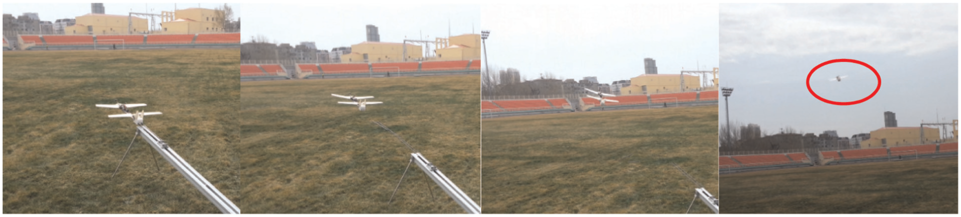
Catapult launched flight experiments under the two conditions have been done in the same environment with identical launching angle, and under both of the two ways, the aircraft has launched excellently. At the same time, we find that the aircraft catapult launched under folded condition has a higher initial take-off speed than the way under unfolded condition and as shown in Figure 17, the flight path of the aircraft approximates level flight at the initial phase. When the aircraft catapult launches without deploying process, it climbs fast as shown in Figure 18. Through a lot of observations during the experiments, we have found that the flight stability under unfolded condition is more difficult to control compared with folded condition launching and this may cause by the effect of the lift overshooting after launching. All these experimental results approximately agree with the simulation results as shown in Figure 16.

Catapult launched under folded condition.
Catapult launched under unfolded condition.
Conclusion
In this study, we have studied the aerodynamic characteristics variation of the morphing aircraft using CFD method. The conclusions are drawn as follows:
Compared with the two types of models, different airfoil configurations have a negligible effect on the overall lift and drag but a great impact on MA and MB. MA remains negative throughout and has a maximum of 0.014 N m, but MB varies a lot and reaches the maximum of 0.046 N m at AOA of 16°. This is mainly attributed to unbalanced downwash flow influence caused by asymmetric airfoils arrangement and the influence shows more obvious on model B, so that model A is more appropriate for the folding configuration.
The rapidly morphing has created significant effects on the unsteady aerodynamics of the whole aircraft to a certain extent during the deploying process, and the lift, drag, and hinge moment of the canard and the wing not all show linear increase. On one hand, it is due to the irregular variation of the airfoil cross section shape. On the other hand, it caused by the effect of the aerodynamic interference and mutual coupling between the canard and wing.
Rapid deformation makes the hysteresis effect been concealed by additional movement effect, and the rapider the deformation rate is, the higher increment the canard lift, drag, and hinge moment have, but the higher decrement the wing lift, drag and hinge moment have. Moreover, the increment of the canard aerodynamic forces and the decrement of the wing aerodynamic forces compensate each other, giving rise to slightly change of the overall lift and drag relative to SSV.
Due to the hysteresis effect generated by the fluid inertia, the overall lift and drag of the aircraft present delay variation after the morphing UAV catapult launching and the delay under unfolded condition is shorter than the way under folded condition. Meanwhile, the aerodynamics delay effect on the aircraft are approximately agree with and the experimental results. The aircraft launched under folded condition has a higher initial take-off speed and better flight stability compared with folded condition launching.
The research on aerodynamic characteristics is of great significance for control-stability analysis, control laws design, and overall design.
Footnotes
Academic Editor: Teen-Hang Meen
Declaration of conflicting interests
The author(s) declared no potential conflicts of interest with respect to the research, authorship, and/or publication of this article.
Funding
The author(s) disclosed receipt of the following financial support for the research, authorship, and/or publication of this article: The research is supported in part by Self-planned Task (No. SKLRS201501A02) of State Key Laboratory of Robotics and System (HIT), in part by the National Natural Science Foundation of China under Grant 61004076. The authors express gratitude for the financial support.