
Abstract
Hybrid power technology is a practicable method for construction machinery to improve fuel utilization and reduce emissions. In this article, in order to achieve the maximum degree of energy conservation for hybrid hydraulic excavator, a study on a control strategy of the hybrid power train system for a 20-t hybrid hydraulic excavator is conducted. A rule-based method which stabilizes the engine operating points in high-efficiency area and maintains the state of charge of the ultra-capacitor in a feasible operating range is presented. Meanwhile, to improve the reliability of the ultra-capacitor, a two-stage state of charge constraint is applied. To validate the effectiveness of the control strategy, a hybrid power train system simulation loading experiment platform is built. The working characteristics and the energy conservation characteristics of the hybrid power train system are explored. Actual load profiles measured from a 20-t traditional excavator are measured and applied in the system. The experimental results show that the proposed control strategy for the hybrid power train system can improve the fuel economy of the hybrid hydraulic excavator. Meanwhile, dynamic performance of the hybrid power train system is better than that of the traditional excavator.
Introduction
With the development of society, the demand for construction machinery is increasing day by day. Excavators have been widely used in varied earth works. However, due to low efficiency and high emissions, traditional hydraulic excavators gradually cannot meet the requirements of times. Therefore, it is urgent to develop a new type of excavator with high efficiency and low emission.
The main factor for low efficiency and high emissions of the traditional excavator is the low efficiency of the power train system. 1 Currently, the main method of improving the efficiency of the power train system is hybrid power train systems (HPTSs).2–4 The HPTSs adopt two or more power sources to drive the load5–7 and to make full use of the advantage of each power source to realize energy-saving.
HPTSs have been applied to vehicles successfully.8–12 Besides, with the development of the technology, many advanced control algorithms have been widely used by electromechanical systems.13–19 However, because of special working conditions and structures of the hybrid hydraulic excavator (HHE), the control strategy for HHE should be reconsidered. In recent decades, a lot of research on the control strategy for the HPTS has been carried out. A rule-based control strategy which controls the machine according to the real-time operating parameters and the pre-set rule is used widely.20,21 Choi et al. 20 used a rule-based control algorithm to improve fuel economy of a compound hybrid excavator in a typical digging process. Simulations were conducted to verify the effectiveness of the control algorithm. Xiao et al. 21 proposed a constant-work-point, double-work-point, and dynamic-work-point control strategies for a HHE. The constant-work-point could stabilize the engine working points, but the state of charge (SOC) of ultra-capacitor would exceed the allowable range after long-term operation. The double-work-point could ensure that the ultra-capacitor SOC within the allowable range. However, frequent switching of engine working points would reduce system stability. The dynamic-work-point control strategy could realize dynamic adjustment of engine working points and ensure the SOC within allowable range. To verify the effectiveness, simulation experiments through asynchronous motor were carried out, respectively. An instantaneous optimal control strategy which controls the machine according to the principle of the minimum fuel consumption of the HPTS at any moment is another typical control strategy as well.22,23 Valerie et al. presented a real-time control strategy for a parallel configuration hybrid-electric vehicle (HEV). The strategy adjusted the HEV behavior based on the current driving conditions of the HPTS. Simulations were carried out to calculate the emissions and energy efficiency. 22 Zhao et al. proposed an instantaneous minimum fuel consumption control strategy for a HHE. The strategy determined the ideal operating points by taking the main influence factors of fuel consumption into consideration, the ultra-capacitor energy variation which was caused by the motor power output is converted to the equivalent fuel consumption and included in the current power-train fuel consumption. 23 Global optimal control strategy is a control strategy which uses the optimal control theory or optimization method to obtain the optimal energy consumption of the HPTS in the whole process.24,25 Dynamic programming (DP) is a typical global optimal control strategy and has been used for parameters design of HPTS in vehicles and excavators. Kim et al. used a hybrid control algorithm based on the equivalent fuel minimization strategy for a compound hybrid excavator. Simulations were conducted and the performance of the control algorithm was verified through real-world vehicle tests. 24 Chen et al. used DP to investigate the power management strategy for a range extended electric vehicle. Different cost functions based on battery energy losses and fuel energy losses were considered to analyze the fuel economy and battery life. Finally, a rule-based control strategy was proposed and simulations were carried out to validate the proposed control strategy. 26 Casoli et al. 27 took advantage of the DP to compare different hydraulic hybrid system layouts and determined the more effective hybrid system layout.
Instantaneous optimal control strategy can achieve the optimal performance of each calculation step in theory. However, it is difficult to guarantee optimal working states of the system in the whole process. While, global optimal control strategy can realize the optimal energy consumption in the whole process. But both of these two control methods need a large amount of computation, which make them difficult to guarantee the real-time control in the practical application.
In this article, a rule-based control of a power train system for a 20-t HHE is proposed. This control strategy stabilizes the engine operating points in high-efficiency area and maintains the ultra-capacitor SOC in a feasible operating range as well. Besides, to improve the reliability of the ultra-capacitor, a two-stage SOC constraint is applied to the control strategy. The article is organized as follows. First, the typical HPTS is introduced, a 20-t excavator load profiles are measured and the working conditions of the excavator are analyzed. Then, the control strategy is proposed. Third, the experimental platform is built and experiments are conducted. Finally, some conclusions are achieved.
Preliminary consideration
According to the different structures of energy flow, the HPTS can be divided into three types.28,29 The different structures of the HPTS are given in Figure 1.
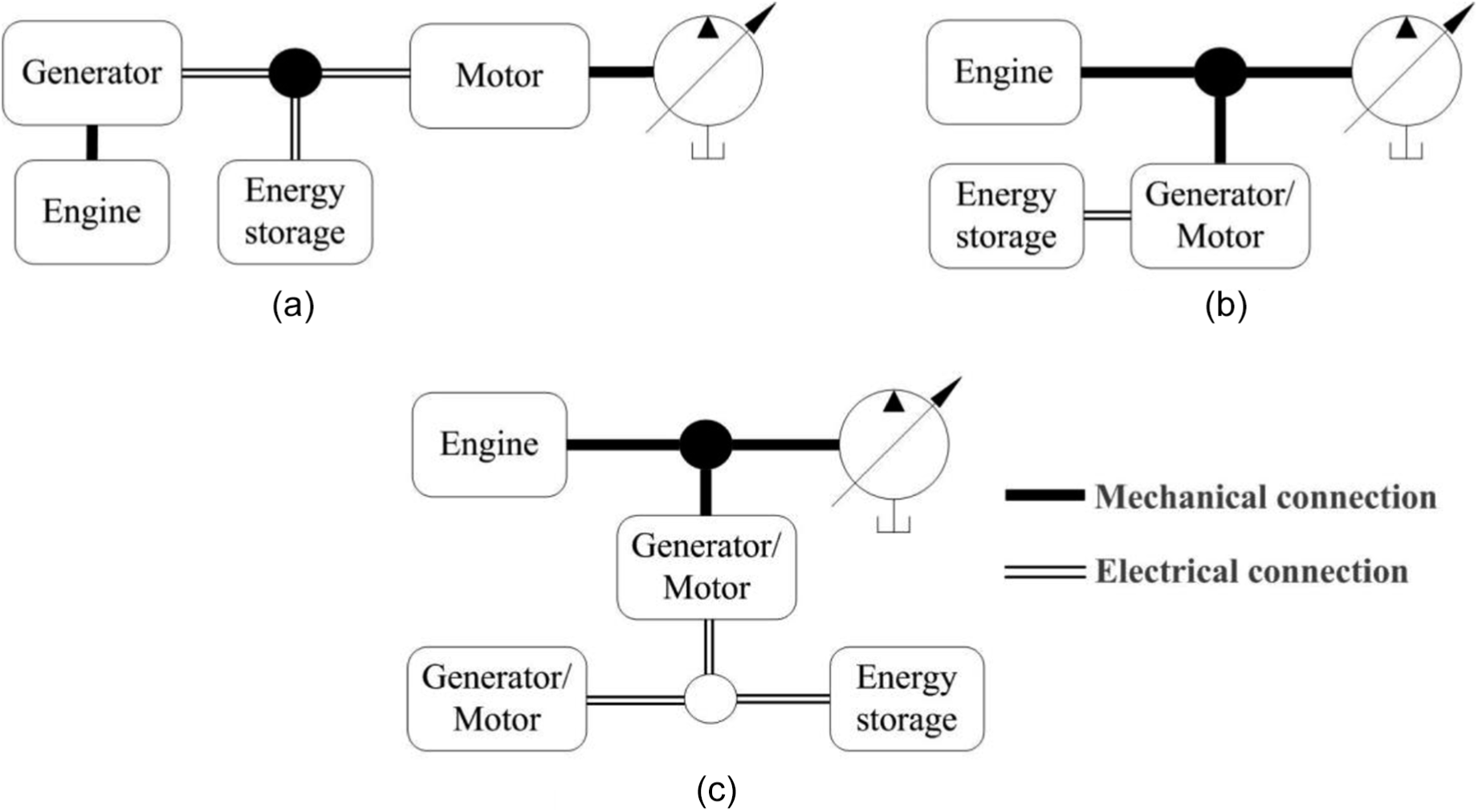
HPTS structures: (a) series type, (b) parallel type, and (c) compound type.
Among these HPTSs, the efficiency of a series type (Figure 1(a)) is the lowest and the cost is most expensive, due to the increase in the energy flow. 30 The efficiency of the compound type HPTS is highest. While, the power train system structure of the parallel type is the same with that of the compound type. The parallel type and the compound type are similar in the control of the power train system. Therefore, the parallel type HPTS is selected as the research object.
A 20-t hydraulic excavator is taken as the research object and its load profiles in five typical working cycles are measured. A typical working cycle of the excavator includes the working processes of digging, lifting, rotating, releasing shovel, and rotating back. The control signal of each actuator is given in Figure 2.

The control signal of each actuator.
By applying the control signals to a 20-t hydraulic excavator, the pressure and flow of pumps are measured and given in Figures 3 and 4, respectively. As can be seen, the working conditions of the hydraulic excavator can be summarized as follows:
Variations of load are periodic. The cycle time depends on the operator to a great extent.
The output pressure and flow of pumps fluctuate sharply.
The load fluctuation frequency is high with large amplitude.

The pressure of hydraulic pumps.

The oil flow of hydraulic pumps.
A traditional hydraulic excavator employs an engine to drive pumps directly, which causes the engine unable to operate in high-efficiency area continuously. In the parallel type HPTS, an electric machine is employed to balance the fluctuation of the load and to maintain the operating points of the engine in high-efficiency area. Besides, in order to improve the frequency response of the electric machine, the energy storage units should have fast charging and discharging performance. Hence, ultra-capacitors are adopted to store the fluctuated energy from the load. To improve the working life of the ultra-capacitor, the SOC of the ultra-capacitor should be varied within a reasonable range. Therefore, the control strategy of the HPTS should consider the energy economy as well as the influence of the ultra-capacitor.
Control strategy
The transfer function of an engine fuel injection quantity can be calculated as

where
As can be found, the main factor for the poor fuel economy of the power train system in traditional excavator is due to the low dynamic response of engine and drastic change of the load, which causes the large deviation between the actual engine speed and the target speed. The engine adjusts the fuel injection continuously according to the target speed. Therefore, the reduction of the difference between the engine target speed and the actual speed can decrease the engine fuel injection quantity and improve the engine economy. Usually, the target speed of the engine in excavator is preset and fixed. Then, the actual speed of the engine should be maintained in a small range of the vicinity of the target engine speed so as to decrease the engine fuel injection quantity.
In the HPTS, an electric machine is employed to assist the engine to drive the load. According to Newton’s second law, the mechanical transmission model of the HPTS can be described as

where Je is the equivalent moment of inertia of the HPTS, Te is the torque of the engine, Tem is the torque of the electric machine, Tp is the torque of the pump, and Be is the damping coefficient.
To stabilize the engine speed, the output torque of the electric machine should be controlled to compensate the influence of the load fluctuation on the angular acceleration of the HPTS and to reduce the actual engine speed fluctuations. Meanwhile, in order to ensure the full combustion of the engine, it is necessary to control the electric machine output torque and to maintain the torque of the engine operated in high-efficiency area as well. The control diagram of the HPTS can be given in Figure 5.

The control diagram of the HPTS.
From Figure 5, the engine controller is to control the engine speed according to the target speed, actual speed, and input torque of the engine. While, the output torque of the electric machine is controlled according to the actual speed and the target speed of the engine. The control objective of the electric machine is to stabilize the engine speed. Meanwhile, to stabilize the torque operating points of the engine in the high-efficiency area, the output torque of the electric machine should be limited to realize the limitation of the engine torque operating points.
Furthermore, because of the limitation of the storage capacity, overcharge and over discharge will reduce the working life of the ultra-capacitor. Therefore, to improve the reliability of the ultra-capacitor, the ultra-capacitor should be run within a reasonable range. The SOC of ultra-capacitor can be expressed as

where Uuc is the real-time voltage value of ultra-capacitor and Uucmax is the maximum allowable voltage value of ultra-capacitor.
Taking the ultra-capacitor SOC as the boundary constraint condition, a rule-based control strategy is applied to the HPTS. First, according to the requirements of the ultra-capacitor, the allowable working range of the ultra-capacitor can be defined as

where Smin is the minimum allowable SOC of the ultra-capacitor and Smax is the maximum allowable SOC of the ultra-capacitor.
In order to maintain the SOC of the ultra-capacitor within a reasonable range and stabilize the operating points of the engine in high-efficiency area as many as possible, a two-stage SOC constraint is used. The two-stage SOC constraint is given in Figure 6. The interval from S1 to S2 is the main operating range of the ultra-capacitor.
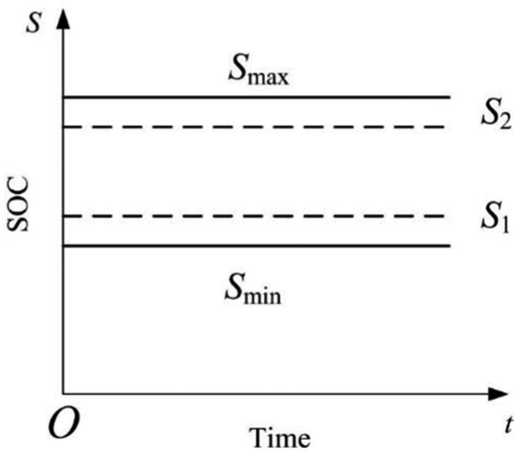
The two-stage SOC constraint.
The rule-based control strategy can be illustrated as follows. If the ultra-capacitor SOC meets the following relationship

At this time, the control objective of the electric machine is to stabilize the operating points of the engine in high-efficiency area. The limitation of the electric machine output torque can be defined as follows. The maximum output drive torque of the electric machine can be obtained as

where Tem+ is the maximum target control torque of the electric machine works in motor mode. Tlmax is the maximum absorbed torque of the pump. Temin2 is the minimum torque of the engine in high-efficiency area. Temmax+ is the maximum allowable output torque of the electric machine, which is decided by output characteristic of electric machine. The maximum absolute output generator torque of the electric machine can be obtained as

where Tem− is the maximum target control torque of the electric machine works in generator mode. Tlmin is the minimum absorbed torque of the pump. Temax2 is the maximum torque of the engine in high-efficiency area. Temmax− is the maximum allowable absorbed generator torque of the electric machine, which is decided by characteristic of electric machine. If the ultra-capacitor SOC meets the following relationship

At this time, the control objective of the electric machine is to stabilize the operating points of the engine in high-efficiency area as well. However, the maximum absolute output generator torque of the electric machine should be reduced as

The maximum output drive torque of the electric machine can be calculated according to equation (6). If the ultra-capacitor SOC meets the following relationship

At this time, the control objective of the electric machine is still to stabilize the operating points of the engine in high-efficiency area. But the maximum output drive torque of the electric machine should be reduced as

The maximum absolute output generator torque of the electric machine can be calculated according to equation (7). If the ultra-capacitor SOC meets the following relationship

At this time, the SOC of the ultra-capacitor has exceeded the minimum allowable interval. The electric machine works in generator mode. The control objective of the HPTS is to drive the load and to charge for the ultra-capacitor simultaneously. The maximum output drive torque of the electric machine is equal to zero. The maximum absolute output generator torque of the electric machine can be calculated according to equation (7). If the ultra-capacitor SOC meets the following relationship

At this time, the SOC of the ultra-capacitor has exceeded the maximum allowable interval. The electric machine works in motor mode. The control objective of the HPTS is to drive the load and to discharge the ultra-capacitor. The maximum absolute output generator torque of the electric machine is equal to zero. The maximum output drive torque of the electric machine can be calculated according to equation (6).
The control diagram of the electric machine in HPTS is given in Figure 7. The target of the electric machine is to stabilize the rotary speed of the HPTS and output the target torque of the electric machine through torque controller. The rotary speed of the engine is monitored and controlled by the rotary speed controller. The electric machine adopts a vector control. The phase currents and the rotary angle are measured to take the vector transform. The SOC of the ultra-capacitor is detected to calculate the output torque and the limitation of the electric machine torque.

The control diagram of the electric machine in HPTS.
Experiment research
To validate the effectiveness of the control strategy, an HPTS simulation loading experiment platform is built. The schematic of the platform is given in Figure 8. The HPTS is formed by the coaxial connection of the engine, the electric machine, and the hydraulic pump. A 20-t excavator load profile is measured and added to the platform through two proportional relief-valves. The main components of the system are given in the Table 1.
Main components in the HPTS simulation loading platform.

HPTS: hybrid power train system.

The schematic of the HPTS simulation loading platform.
The Advantech IPC is used to control the platform. The engine is controlled by the engine controller. The electric machine is controlled by a dSPACE1103 digital signal processor. Each controller is communicated through the controller area network (CAN) communication protocol. Meanwhile, the hydraulic pump and the proportional relief-valves are controlled by the Advantech IPC control card. The signals of the output torque of the engine, the absorbed torque of the hydraulic pump, the output pressure of the hydraulic pump, and the current and the voltage of the ultra-capacitor are acquired by the Advantech IPC acquisition card. The HPTS control strategy mentioned above is realized in Advantech IPC. The torque command is transmitted to the dSPACE1103 through CAN card. The part of the platform is given in Figure 9.

The HPTS simulation loading platform.
The actual load profiles measured from a 20-t hydraulic excavator is added to the platform. The displacements and the pressure of the hydraulic pump are given in Figures 10 and 11, respectively.

Displacements of the hydraulic pump: (a) pump 1 and (b) pump 2.

Pressure of the hydraulic pump: (a) relief-valve 1 and (b) relief-valve 2.
To compare the energy-saving and the dynamic performance of the HPTS with that of the traditional hydraulic excavator, conveniently, the load profiles are added to the traditional engine direct-drive power train system as well. The target speed input signal is 1800 r/min. The engine operating points in the traditional hydraulic excavator and the HPTS are distributed on the engine universal characteristic curve as shown in Figure 12. As can be found, the operating points of the engine in the HPTS are more centralized compared with that of the traditional engine direct-drive power train system and are distributed in the areas with high efficiency.

The distribution of engine operating points of the traditional hydraulic excavator and the HPTS on the engine universal characteristic curve.
The rotary speed of the traditional engine direct-drive power train system and the HPTS are given in Figure 13. In the traditional engine directly power train system, the amplitudes of the rotary speed varies greatly. However, the varied amplitudes of the engine rotary speed is small. Besides, the rotary speed of the engine is mainly operated near 1800 r/min.

The rotary speed of the engine in traditional engine direct-drive power train system and the HPTS.
The output toque of the engine in the traditional engine direct-drive power train system and the HPTS are given in Figure 14. As can be found, the output torque of the engine in the HPTS is relatively stable compared to that of the traditional engine direct-drive power train system.

The output torque of the engine in traditional engine direct-drive power train system and the HPTS.
In order to study the energy saving of the HPTS, the same load profiles shown in Figures 10 and 11 are added to the HPTS and the traditional engine direct-drive system repeatedly. The energy consumption of the engine can be obtained from the engine controller through the CAN communication data. Meanwhile, in the HPTS, due to the usage of the electric machine and the ultra-capacitor, the energy stored in or consumed from the ultra-capacitor should be taken into account. Therefore, the equivalent fuel consumption of the HPTS should be used to estimate the energy consumption of the HPTS. The equivalent fuel consumption of the HPTS can be calculated as

where JHPTS is the equivalent fuel consumption of the HPTS. JHPTS-e is the fuel consumption of engine in the HPTS. Jc is converted engine fuel consumption from energy consumed or stored in the ultra-capacitor in accordance with the engine universal characteristic curve in a certain working time. Compared with the starting time, if the energy of the ultra-capacitor increases, Jc is positive. Otherwise, it is negative. To scale the energy efficiency of the HPTS, the energy-saving rate of the HPTS is defined as
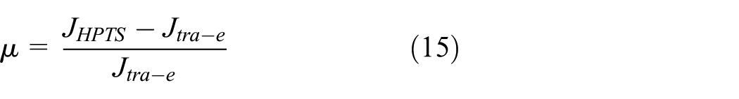
where µ is the energy-saving rate of the HPTS. Jtra-e is the energy consumption of engine in the traditional engine direct-drive system. Apply the same load to the two power train systems in the same period of time, the energy-saving rate of the HPTS can be improved by about 6.98% compared with that of the traditional engine direct-drive system.
Conclusion
In this article, a rule-based control strategy which stabilizes the engine operating points in high-efficiency area and maintains the ultra-capacitor SOC in a feasible operating range as well is proposed for the HPTS in HHE. Meanwhile, to improve the reliability of the ultra-capacitor, a two-stage SOC constraint is applied to the control strategy. The effectiveness of the control strategy is validated by the experiments research. The results indicate that the control strategy can effectively stabilize the engine speed, which means the HPTS has better dynamic characteristics and can ensure the sufficient supply of the hydraulic system. Moreover, the control strategy for the HPTS can improve the fuel efficiency of the engine by about 6.98% compared to that of the traditional engine direct-drive system. Furthermore, the ultra-capacitor can be run in a reasonable area.
Footnotes
Handling Editor: Jose Ramon Serrano
Declaration of conflicting interests
The author(s) declared no potential conflicts of interest with respect to the research, authorship, and/or publication of this article.
Funding
The author(s) disclosed receipt of the following financial support for the research, authorship, and/or publication of this article: The authors acknowledge the financial support of the National Natural Science Foundation of China (grant no. 51505160), Natural Science Foundation of Fujian Province (grant no. 2017J01087), Open Foundation of the State Key Laboratory of Fluid Power and Mechatronic Systems (grant no. GZKF-201611), and China Postdoctoral Science Foundation (grant no. 2017M612139).