
Abstract
In order to enable the vehicle to change among the tracks, the stock and switch rails are separated and provided with different rail resilience levels on the baseplate in the railway turnout switch panel. Therefore, there will be vertical relative motion between stock/switch rails under wheel loads, and the relative motion will change the combined profile of stock/switch rails and consequently affect the wheel–rail contact mechanics. A method is developed in this article to investigate the effect of the relative motion of stock/switch rails on the wheel–rail contact mechanics along the railway turnout switch panel. First, the possible rigid wheel–rail contact points, called primary and secondary stock/switch rail contact points, are calculated based on the trace line method; second, the actual contact points are determined by the presented equations; finally, the distribution of wheel–rail contact forces on the stock/switch rails is obtained based on the continuity of interface displacements and forces. A numerical example is presented in order to investigate the effect of the relative motion of stock/switch rails on the wheel–rail contact points, stresses, and forces, and the results are presented and discussed.
Keywords
Introduction
A railway turnout is an essential component of railway facilities consisting of, moving in the longitudinal direction along the rails, a switch panel, a closure panel, and a crossing panel. 1 The switch panel is mainly used to guide a vehicle onto the main line or a diverging line, and the wheel of vehicle is transferred between the stock rail and switch rail. 2 At this time, skipping wheel–rail contact points can cause strong dynamic wheel–rail interaction. This interaction is one of the main causes for damage to the switch panel rail such as wear and rolling contact fatigue.3–5 As shown in Figure 1, when the wheels pass the switch panel, up to six types of possible wheel–rail contact behaviors will be caused due to the gradual change of the switch rail profile and the spatial position of the wheel-set. The wheel–rail contact relationship is very complicated. In addition, the mutual restraint between the switch rail and stock rail is very weak, and the supporting elasticity from the slide baseplates on the switch rail and stock rail is different. 2 Their relative motion under wheel loads can influence the wheel–rail contact at all times; therefore, it is very important to study the influence of the relative motion between the switch rail and stock rail on the wheel–rail contact mechanics in a turnout switch panel.

Wheel–rail contact on a railway turnout switch panel.
Researchers from different countries have been studying the wheel–rail contact behavior on turnout switch panels. Wang 2 introduced a calculation model for transferring and distributing wheel loads in the switch panel when establishing a coupling dynamic model for the vehicle-turnout system and verified the correctness of this model through a field test. The relative motion between a switch rail and a stock rail was analyzed for this model. However, considering the assumed conditions such as conical wheel tread and the wheel–rail contact point on the rail top, it is hard to study the wheel–rail contact behavior in switch panels correctly. Xu et al.6,7 studied the contact mechanics between wheels and stock/switch rails, including the wheel–rail contact stress and the equivalent internal rail stress, using finite element software. For this model, the stock rail and switch rail were considered separately, so the calculated results were highly accurate; however, the calculation efficiency was very low. Kassa et al., 8 Kassa and Nielsen, 9 and Alfi and Bruni 10 considered a switch rail and a stock rail as one rail participating in the system’s vibration when studying the medium/low frequency (0–500 Hz) dynamic interaction between a vehicle and a turnout, and the wheel–rail contact problem was solved based on the Hertzian theory. Sugiyama et al.11,12 presented a numerical method for calculating the geometric wheel–rail contact parameters in a turnout zone. For this method, the profile data of a switch rail and a stock rail at each section are combined for the sake of easy calculation. Sebes et al. 13 solved the wheel–rail contact problem based on the semi-Hertzian method when establishing a coupling dynamic model for the vehicle-turnout system, significantly improving the wheel–rail contact calculation accuracy. Ren et al. 14 and Ren 15 presented a solution for calculating the two-point contact between the wheel and switch/stock rails in a turnout zone based on the deformation hypothesis with regard to wheel–rail contact. However, for this method, the wheel–rail contact model was established based on the Hertzian theory, and multi-point contact conditions cannot be considered between wheels and single rail even though multi-point contact is more frequently seen after wheel and rail wear. The correctness of the research findings will be influenced if this method is adopted. The influence of the relative motion between a switch rail and a stock rail on the wheel–rail contact behavior is neglected in the literature.8–15
In this article, the wheel–rail contact characteristics of turnout switch panels were studied based on the relative spatial positions between a switch rail and a stock rail as well as the supporting elasticity from the slide baseplates, and a solution for calculating the contact geometries and contact forces of switch panels when considering the relative motion between a switch rail and a stock rail is presented. The influence of the relative motion between a switch rail and a stock rail on the wheel–rail contact mechanics is analyzed by taking a switch panel from the Chinese No. 18 (turnout angle 1:18) high-speed railway turnout as an example, and an analysis is performed comparing the calculated results obtained when the relative motion between the switch rail and stock rail is not considered.
Relative motion between switch rail and stock rail
As shown in Figure 2, a switch rail and a stock rail are installed on a slide baseplate. The difference is that no part is set between the switch rail and slide baseplate. The slide baseplate gives a rigid support to the switch rail. No vertical displacement of the switch rail relative to the slide baseplate can occur under wheel loads. The stock rail is connected to the slide baseplate through a rubber pad of the fastener system, so vertical displacement relative to the slide baseplate can occur under wheel loads.

Combined structure of switch rail and stock rail.
Wheel loads mainly influence the vertical displacement of the stock rail, changing the combined profile of switch rail and stock rail and finally influencing the wheel–rail contact behavior. Therefore, in order to simplify the calculations in this article, the influence of the lateral and twisting motion of the rail is neglected.
Wheel–rail contact point calculation model
According to the relative spatial positions between the switch rail and stock rail and the conditions of the support from the slide baseplate on the switch rail and stock rail, a calculation method of wheel–rail contact points considering the relative motion between the switch rail and stock rail is presented; the detailed steps for the calculation are shown below:
The rigid contact point positions between wheels and switch/stock rails are calculated according to the trace line method 16 in order to obtain the positions of primary and secondary wheel–rail contact points.
The actual positions of wheel–rail contact points according to the positions of primary and secondary contact points are obtained as well as the relation between the vertical displacement of the rail and the rigid body penetration with regard to vertical wheel–rail contact.
Positions of primary and secondary contact points
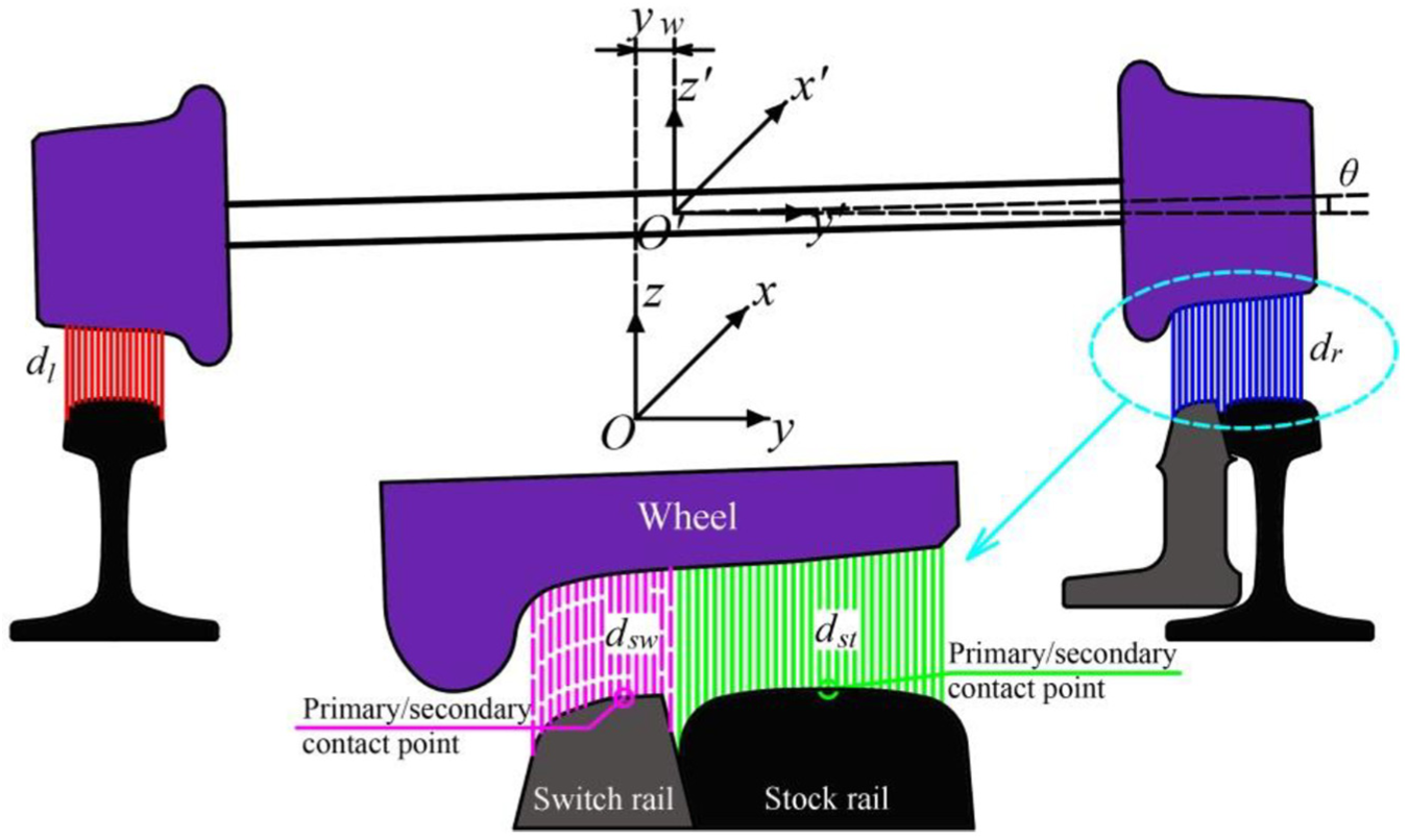
The positions of primary and secondary contact points between the wheel and switch/stock rails are calculated based on the fundamental principle of the trace line method according to the spatial restraint relation between the wheels and the rails. During calculations based on the trace line method, the wheels and rails are considered as rigid bodies, and the lateral wheel-set displacement is yw at the section x distance away from the switch rail tip. As shown in Figure 3, the head profiles of the stock rail and switch rail are first combined as one part to complete the calculation, thus the two distance parameters dl and dr are obtained, where dl is the minimum vertical distance from the left wheel tread to the left rail and dr is the minimum vertical distance from the right wheel tread to the right rail. The rolling angle θ of the wheel-set can be adjusted based on the iterative method. When the two distance parameters dl and dr satisfy equation (1), the geometric wheel–rail contact parameters can be obtained

where ε is the calculated control accuracy. A sufficiently low value should be used during the calculation. In this article, the given value is 10−6 mm. Figure 3 shows the calculation for the positions of primary and secondary wheel–rail contact points, where Oxyz is the corresponding coordinate system of the track center, and O′x′y′z′ is the corresponding coordinate system of the wheel-set center.
Calculation of primary and secondary wheel–rail contact points.
Second, the stock rail and switch rail profiles are separated for the calculation when the wheel-set position is maintained unchanged. During this process, the two distance parameters dst and dsw are calculated, where dst is the minimum vertical distance from the right wheel tread to the stock rail and dsw is the minimum vertical distance from the right wheel tread to the switch rail. The two distance parameters should satisfy equation (2)

If dr is equal to dst, the primary and secondary wheel–rail contact points will be at the stock rail and switch rail, respectively. Similarly, if dr is equal to dsw, the primary and secondary wheel–rail contact points will be at the switch rail and stock rail, respectively. When the minimum vertical distance between the wheels and rail is calculated, the wheel–rail profile should first be fit according to the cubic spline curve function and then the minimum vertical wheel–rail distance can be obtained through interpolation calculation. The vertical distance difference between the primary and secondary contact points can be obtained according to equation (3). The primary and secondary contact points are the possible contact positions between the wheel and switch/stock rails. The actual positions of the wheel–rail contact points will be further analyzed in section “Actual positions of contact points”

Actual positions of contact points
There are only three kinds of contact between the wheel and switch/stock rails—contact between only the wheel and stock rail, between only the wheel and switch rail, and between the wheel and stock/switch rails at the same time. The displacement relation among the three items when only the stock rail bears the wheel load and when only the switch rail bears the wheel load is shown in Figure 4. In this figure, hs is the vertical distance from the secondary contact point to the wheel tread, and hms is the vertical distance difference between the primary and secondary contact points. The calculation is performed according to equation (3), where wst,P is the vertical rigid body displacement when only the stock rail bears the wheel load and δst,P is the vertical rigid approach between the wheel and stock rail when only the stock rail bears the wheel load. Similarly, δsw,P is the vertical rigid approach between the wheel and switch rail when only the switch rail bears the wheel load.

Wheel–rail displacement relation: (a) only the stock rail bears the wheel load and (b) only the switch rail bears the wheel load.
As shown in Figure 4(a), when only the stock rail bears the wheel load, the primary contact point is at the stock rail, which is the actual position of the wheel–rail contact point, while the secondary contact point is at the switch rail, which does not contact with the wheel. Therefore, according to the wheel–rail displacement relation, the vertical distance hs from the secondary contact point to the wheels at this time should satisfy equation (4)

Similarly as shown in Figure 4(b), when only the switch rail bears the wheel load, the primary contact point is at the switch rail, which is the actual position of the wheel–rail contact point, while the secondary contact point is at the stock rail, which does not contact with the wheel. Therefore, according to the wheel–rail displacement relation, the vertical distance hs from the secondary contact point to the wheels at this time should satisfy equation (5)

In short, when the vertical distance from the secondary contact point to the wheel tread satisfies equations (4) and (5), the primary contact point will be the only wheel–rail contact point, and the wheel only contact with the stock rail or switch rail. If it does not satisfy them, both the primary and secondary contact points will be the actual wheel–rail contact points, and the wheel contact with the switch rail and stock rail at the same time. For equations (4) and (5), the vertical wheel–rail rigid approach is calculated according to the ANALYN model, 17 which is a virtual penetration principle method. 18 This wheel–rail contact model has high calculation accuracy and efficiency and can be adopted to solve single wheel/single rail multi-point contact problems.
In addition, the rail is supported by the slide baseplate at intervals along the longitudinal direction of the turnout switch panel; therefore, the supporting model for the rail can be simplified as a point supporting beam model. As shown in Figure 5, the corresponding rail displacement is calculated separately according to the numerical calculation method when moving loads are exerted on the fastener and midspan. In the figure, the moving loads Pf and Pm are 60.8 kN, the flexural rigidity EI of the rail is 6.63 × 10⁶ N m 2 , the point supporting rigidity kr is 300 kN/mm, the distance sd between two consecutive point supporting positions is 0.6 m, and X and Z refer to the longitudinal and vertical direction of the rail. These parameters are obtained from Chinese High Speed Railway. For example, the moving load is half of axle load of the Chinese high-speed vehicle CRH2. The flexural rigidity of the rail is calculated based on the sectional characteristics of CHN60 rail. The point supporting rigidity is equal to the vertical stiffness of rail pad used in Chinese High Speed Railway. Some parameters can be found in Wang. 2

Rail supporting beam model.
It can be seen that in Figure 5, the influence of the wheel load position on the vertical displacement of the rail is weak. The main reason for this is that the flexural rigidity of the rail is high and the distance between two consecutive supporting points is short; therefore, the point supporting beam model of the rail can be further simplified as a consecutive supporting beam model. As shown in equation (6), the vertical displacement of the stock rail under the whole wheel load is calculated based on the Winkler Foundation method. It should be noted that this article is mainly concerned with the relative motion between the switch rail and stock rail on the surface of the slide baseplate, and therefore, sub-rail foundation types are not dealt with at this time

where ur is the continuous supporting rigidity.
Wheel–rail contact force calculation model
When only the stock rail or switch rail bears the wheel load, the wheel–rail contact force will be equal to the wheel load. When the switch rail and stock rail bear the wheel load together, the contact forces between the wheel and switch/stock rails are unknown. This article derives a contact force calculation method based on the coordinative relation between the displacement and forces with regard to the wheel, switch rail, and stock rail before and after deformation due to wheel–rail contact.
Figure 6 shows the force and displacement relation among the three items before and after wheel–rail contact when the wheel contact with the stock rail and switch rail at the same time. In this figure, P is the total vertical wheel–rail force, Psw is the vertical wheel–rail contact force between the wheel and switch rail, δsw is the vertical rigid approach between the wheel tread and switch rail, Pst is the vertical wheel–rail contact force borne at the stock rail side, δst is the vertical rigid approach between the wheel tread and stock rail, and wst is the vertical rigid body displacement of the stock rail.
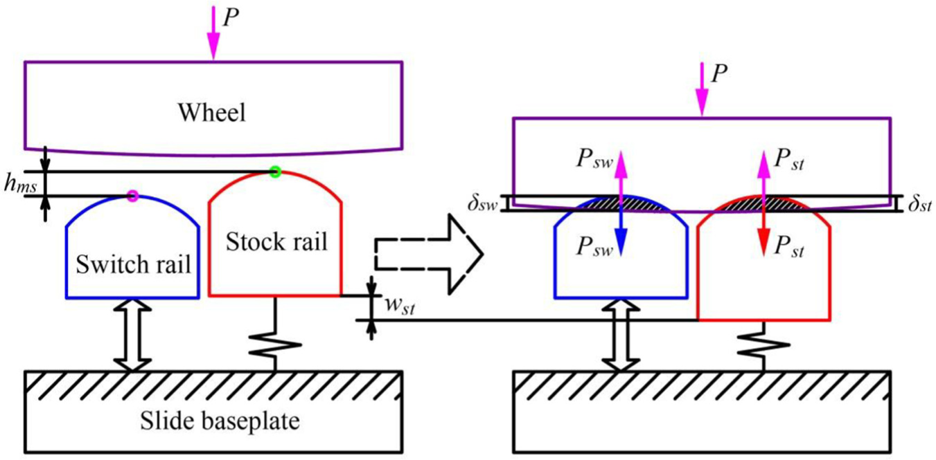
Calculation model for distribution of wheel–rail contact force.
The following can be obtained according to the coordinative relation among the wheels, switch rail, and stock rail

In order to verify whether the wheel–rail contact rigidity is subject to linear variation, the wheel–rail contact rigidity under different vertical wheel–rail forces is calculated based on the Hertz contact model and ANALYN model by taking the LMA wheel profile and CHN60 rail with 1:40 rail cant as an example, as shown in Figure 7. The vertical force increases from 1 to 100 kN, and the calculation step is 1 kN.

Variation of wheel–rail contact rigidity.
As shown in Figure 7, the wheel–rail contact rigidity variations obtained based on the two calculation models basically coincide. When the vertical wheel–rail forces increase from 1 to 100 kN, the wheel–rail contact rigidity will increase from 2.0 × 10⁵ to 9.6 × 10⁵ N/mm. The wheel–rail contact rigidity calculated based on the ANALYN model is not subject to a linear variation and will be greatly underestimated if it is calculated based on a unit force. Therefore, similar to the Hertzian contact theory, when the ANALYN model for wheel–rail contact calculation is used, the relation between the vertical wheel–rail force and vertical wheel–rail penetration can be expressed as

where δst(1) is the vertical rigid approach between the wheel and stock rail under a unit vertical force, and δsw(1) is the vertical rigid approach between the wheel and switch rail under a unit vertical force.
For the wheel, the following can be obtained according to the force interaction principle and equilibrium condition

Considering equations (6)–(9), the vertical wheel–rail force borne by the switch rail can be obtained and then the vertical wheel–rail force borne by the stock rail can be calculated according to equation (9). When the relative motion between the switch rail and stock rail is ignored, for equation (7), the displacement coordination condition for the switch rail and stock rail before and after wheel–rail contact will change, that is, the vertical rigid body displacement of the switch rail at this time will be 0. For other calculations, the processes are similar.
Computer program
According to the wheel–rail contact point calculation method mentioned in section “Wheel–rail contact point calculation model” as well as the wheel–rail contact force distribution calculation model mentioned in section “Wheel–rail contact force calculation model,” a computer program was compiled based on the MATLAB language, which can be adopted to study the influence of the relative motion between the switch rail and stock rail in the turnout switch panel on the wheel–rail contact mechanics. For the flowchart of this computer program, see Figure 8.

Flowchart for wheel–rail contact characteristics calculation in switch panel.
Example analysis
A switch panel of Chinese CN60-1100-1:18 high-speed railway turnout is taken as the research object to study the influence of the relative motion between the switch rail and stock rail on the wheel–rail contact mechanics and compare the obtained results when the relative motion between the switch rail and stock rail is ignored based on the program for wheel–rail contact calculation compiled in the previous section. The computational contents include the wheel–rail contact points, contact stresses, and forces. The key parameters 2 required for calculation are shown in Table 1, and a wheel tread called LMA of China railway is adopted.
Key calculation parameters in the example.

Switch rail and stock rail profiles
When a vehicle passes the turnout switch panel with facing move, the wheel will gradually transfer to the switch rail from the stock rail. In order to achieve a smooth transfer, the switch rail has been made into a variable section rail. The width of the top of the switch rail has been increased from 0 to 72.2 mm, during which the height of the top of the switch rail has been gradually increased until it reaches the top height of the stock rail. Figure 9 shows the switch rail and stock rail profiles at sections 0, 0.760, 3.037, 5.314, 7.591, and 10.962 m away from the switch rail tip. The switch rail and stock rail profiles at other sections can be obtained according to the key sectional profiles based on the cubic spline function fitting and interpolation calculation.

Stock rail and switch rail profiles at key sections.
Position of wheel–rail contact points
The positions of wheel–rail contact points at sections 5.2, 5.8, and 6.4 m away from the switch rail tip are calculated successively (see Figure 10). The upper part shows the calculated results when the relative motion between the switch rail and stock rail is considered. The lower part shows the calculated results when the relative motion between the switch rail and stock rail is ignored. The lateral displacement of the wheel-set is kept within 0–12 mm; the calculation step is 0.5 mm. When the wheel moves toward the switch rail, the direction is considered as positive.

Distribution of wheel–rail contact points: (a) x = 5.2 m, (b) x = 5.8 m, and (c) x = 6.4 m.
It can be seen from Figure 10 that for the section 5.2 m away from the switch rail tip, all the wheel–rail contact points are on the stock rail except that the wheel flanges contact with the switch rail, while for the section 6.4 m away from the switch rail tip, all the wheel–rail contact points are on the switch rail. During this process, the wheel–rail contact points are gradually transferred to the switch rail from the stock rail. When the wheel contacts the switch rail and stock rail at the same time, the wheel–rail contact points will be greatly influenced by the relative motion between the switch rail and stock rail. For the section 5.8 m away from the switch rail tip, when the relative motion between the switch rail and stock rail is considered and the lateral wheel-set displacement is within 0–9 mm, the wheel will contact the switch rail and stock rail at the same time. However, when the relative motion between the switch rail and stock rail is ignored, the wheel can only contact the switch rail and stock rail at the same time when the lateral wheel-set displacement is within 0–1 mm and 8.5–9 mm.
Wheel–rail contact stresses
It can be seen from Figure 10 that for the section 5.8 m away from the switch rail tip, the wheel can contact the switch rail and stock rail at the same time under the conditions of some lateral wheel-set displacement values. Therefore, the section (x = 5.8 m) is chosen as an example in this article; the positions and shapes of wheel–rail contact patches as well as the normal contact stresses considering the relative motion between the switch rail and stock rail are shown in Figure 11.

Normal wheel–rail contact stresses considering relative motion between switch rail and stock rail: (a) yw = 0 mm, (b) yw = 4 mm, (c) yw = 8 mm, and (d) yw = 12 mm.
It can be seen from Figure 11 that when the lateral wheel-set displacement results are 0, 4, and 8 mm, the wheel will contact the switch rail and stock rail at the same time, the maximum stresses at the switch rail side will be 1082, 397, and 1111 MPa, respectively, and the maximum stresses at the stock rail side will be 1348, 3009, and 2551 MPa, respectively. When the lateral wheel-set displacement reaches 12 mm, the wheel flange will contact the track gauge corner of the switch rail, the wheel only contact the switch rail, and the maximum wheel–rail contact stress at the switch rail side can reach up to 4125 MPa. A high normal wheel–rail stress is also one of the main reasons for the side abrasion of the switch rail. Figure 12 shows the wheel–rail contact patch positions, shapes, and normal contact stress distribution when the relative motion between the switch rail and stock rail is ignored.

Normal wheel–rail contact stresses ignoring the relative motion between switch rail and stock rail: (a) yw = 0 mm, (b) yw = 4 mm, (c) yw = 8 mm, and (d) yw = 12 mm.
It can be seen from Figure 12 that when the lateral wheel-set displacement is 0 mm, the wheels will contact the switch rail and stock rail at the same time, and the maximum contact stresses at the switch rail side and stock rail side will be 796 and 1555 MPa, respectively. Compared to the situation wherein the relative motion between the switch rail and stock rail is considered, the wheel–rail contact states are different, even though the wheel also contacts the switch rail and stock rail at the same time. When the lateral wheel-set displacement results are 4 and 8 mm, the wheels only contact the stock rail, and the maximum contact stresses at the stock rail side are 3027 and 2799 MPa, respectively. When the lateral wheel-set displacement is 12 mm, the calculated result is the same as that when the relative motion between the switch rail and stock rail is considered.
Wheel–rail contact forces
When passing the turnout with facing move, the vehicle will go through three stages, that is, only the stock rail bears the wheel load, the stock rail and switch rail bear the wheel load together, and only the switch rail bears the wheel load. This article, by taking the switch rail bearing the variable vertical wheel–rail force as an example, explains the influence of the relative motion between the switch rail and stock rail on the transfer and distribution of wheel–rail contact forces. The defined distribution coefficient of the vertical wheel–rail force at the switch rail side is

Figure 13 shows the isolines of the distribution coefficients for the vertical wheel–rail force at the switch rail side for calculating the lateral wheel-set displacement and section positions. The lateral wheel–rail displacement range is kept from 0 to 12 mm; the calculation step is 0.1 mm. The section positions ranges are from 5.2 to 6.2 m away from the switch rail tip, and the calculation step is 0.01 m.

Isolines of distribution coefficients for vertical wheel–rail force at switch rail side: (a) relative motion between switch rail and stock rail considered and (b) relative motion between switch rail and stock rail ignored.
In Figure 13, the deep blue sections show when only the stock rail bears the wheel load, the deep red sections show when only the switch rail bears the wheel load, and the transition sections in the middle show when the switch rail and stock rail bear the wheel load at the same time. It can be seen that the relative motion between the switch rail and stock rail can greatly influence the vertical wheel–rail forces. If the lateral wheel-set displacement at a section 5.8 m away from the switch rail tip is 3 mm, when the relative motion between the switch rail and stock rail is considered, the distribution coefficient of the vertical wheel–rail force at the switch rail side will be 0.19. However, when the relative motion between the switch rail and stock rail is ignored, no vertical wheel–rail force will be borne at the switch rail side and the distribution coefficient will be 0.
Conclusion
The influence of the relative motion between a switch rail and a stock rail of a turnout switch panel on the wheel–rail contact mechanics is studied in this article. First, the positions of contact points between wheel and the switch/stock rails are obtained according to the relative spatial positions between the switch rail and stock rail and the supporting conditions from the slide baseplate on the switch rail and stock rail. Second, when the switch rail and stock rail bear the wheel load at the same time, the distribution of the wheel load on the switch rail and stock rail can be solved based on the coordinative relation between the force and displacement when the wheel, switch rail, and stock rail contact with each other. Finally, a related computer program is compiled based on the MATLAB language according to the established model in order to calculate the wheel–rail contact point distribution, wheel–rail contact stresses, and contact forces distribution at different positions along the longitudinal direction of the line.
Based on the method presented in this article, by taking the switch panel of Chinese CN60-1100-1:18 high-speed turnout as the research object, the influence of the relative motion between the switch rail and stock rail on the wheel–rail contact point positions and stresses and forces are studied, and an analysis is made comparing the calculated results obtained when the relative motion between the switch rail and stock rail is ignored. The calculated results show that the relative motion between the switch rail and stock rail can greatly influence the mechanical wheel–rail contact characteristics, such as the wheel–rail contact point position, wheel–rail contact patch shape, normal contact stress, and vertical wheel–rail force transfer and distribution.
Since the relative motion between the switch rail and stock rail is considered, the method presented in this article can be adopted to improve research on the mechanical simulation of the vehicle-turnout system. This article only introduces a method for wheel–rail contact calculation when the relative motion of the switch rail and stock rail is considered based on the static conditions. However, the dynamic wheel–rail contact state is dependent on those parameters such as the dynamic position of a wheel-set, the dynamic relative positions of the switch rail and stock rail, and the dynamic wheel–rail interaction force, and therefore, the application of this method in vehicle-turnout system dynamics will be done in the future work.
Footnotes
Appendix 1
Handling Editor: Davood Younesian
Declaration of conflicting interests
The author(s) declared no potential conflicts of interest with respect to the research, authorship, and/or publication of this article.
Funding
The author(s) disclosed receipt of the following financial support for the research, authorship, and/or publication of this article: This work was supported by the National Natural Science Foundation of China (51425804, 51378439, and 51608459) and the Key Project of the China’s High-Speed Railway United Fund (U1234201 and U1734207).