
Abstract
As a new gear pair with variable transmission ratio, curve-face gear can be applied to percussion drill to simplify the structure. For the application of curve-face gear pair, the loaded tooth contact analysis of curve-face gear pair should be taken into consideration. According to the gear meshing theory, the mathematical equations for the tooth surface of non-circular gear and curve-face gear were derived, and the meshing equations of this gear pair were also derived. Based on the method of the principal curvatures of space curve face, the variations in principal curvatures of non-circular gear and curve-face gear were proposed separately. With the mathematical method of Boussinesq problems, the loaded tooth contact analysis of curve-face gear pair was presented. The semi-major axis and semi-minor axis of contact ellipse on the surface of curve-face gear were proposed and simulated, and the maximum contact stress on contact area and its trend with the change in meshing situation were investigated, and the principles in the half cycle were also investigated. The tooth contact paths and the calculation method for the loaded tooth contact analysis of curve-face gear pair were verified by the rolling experiment.
Introduction
Face gear transmission system has many advantages, such as high contact ratio, compact structure, good bearing capacity, and not sensitive to misalignment. So, it has great application prospects in aerospace, shipbuilding industry, and vehicle engineering.1–3 For the better understanding of face gear pair, many scholars at home and abroad have done a lot of researches on the theoretical and engineering applications of traditional face gear. C Zanzi and JI Pedrero 4 modified the cylindrical gear of face gear pair and studied the contact stress and bending stress on the tooth surface. M Guingand et al. 5 have done the contact analysis on the tooth surface, and the analysis of bending stress and the general test methods of bending stress were presented. FL Litvin et al.6–9 studied the application and basic theories of face gear such as the modeling and modification of tooth surface, tooth contact analysis, and the analysis of contact stress. Also, the tooth contact analyses of the orthogonal offset face-gear drive have been investigated. Litvin et al. 10 achieved amount of results and developed the transmission theory of localized contact for face gear. According to the meshing theory, the comparisons of theoretical tooth contact analysis and finite element analysis have been presented with significant results.11–13
Because of the special structure of curve-face gear pair, it has great application prospects in the field of textile machinery, agricultural machinery, construction machinery, and automotive industry. Based on the localized meshing theory, the curve-face gear pair, which is processed by the same shaper cutter, can be regarded as meshing with point contact on the surface of tooth. C Lin et al.14–16 focused on the studies of the theoretical design, three-dimensional (3D) modeling, manufacturing of this gear type, the measurement of tooth surface, and the engineering applications of this kind of gear pair. But the loaded tooth contact analyses of the gear pair were not studied. Tooth contact quality is an important evaluation index for the dynamic transmission characteristics of gear pair, and loaded tooth contact analysis (LTCA) is beneficial to the design, manufacturing, and engineering applications of gear drive, so the LTCA is necessary for curve-face gear pair.
In this article, according to the gear meshing theory and the spatial coordinate transformation principle, the meshing equations of curve-face gear are established and the load tooth contact analysis of curve-face gear has been proposed. These results provide the theoretical supports for further analysis and application of curve-face gear (Table 1).
List of notations.

The model of curve-face gear pair
During the meshing process, the non-circular gear do pure rolling on the pitch curve of curve-face gear, which shows the characteristics of variable transmission ratio. The coordinates of this gear pair can be shown as follows.
As shown in Figure 1, coordinate
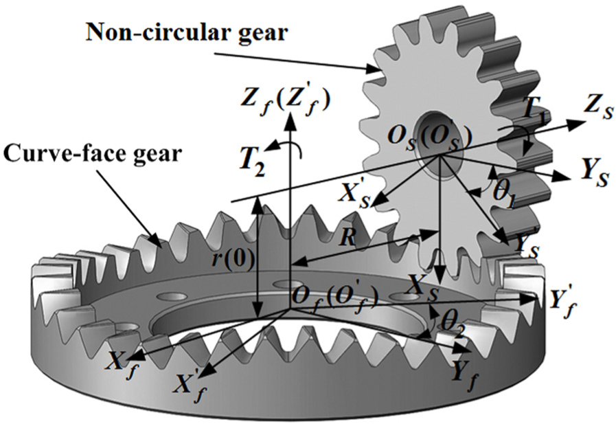
Coordinate systems of curve-face gear pair.
The meshing equation of curve-face gear pair
The tooth surface of curve-face gear pair
As shown in section “The model of curve-face gear pair,” the non-circular gear rotates clockwise in the meshing process of this curve-face gear pair. And according to the generating method, the left tooth surface of non-circular gear

where

The tooth surface of shaper cutter.
According to the gear meshing theory and the spatial coordinate transformation principle, in coordinate
And the meshing equation in the meshing process can be established as follows

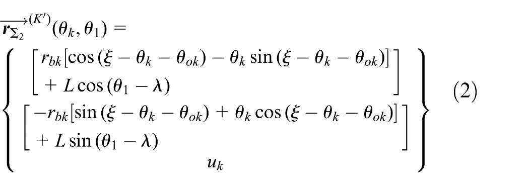
According to the principle of tooth surface, the equation of the left tooth surface of non-circular gear, in coordinate
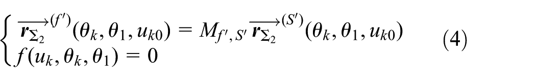
With the simplification of equation (4), the left tooth surface of non-circular gear can be shown as

where
Based on the same method of

Meshing equation of curve-face gear pair
According to the gear meshing theory, there will be the same position vector and normal vector at meshing point

Meshing point of curve-face gear pair.
Equation (7) shows the meshing equation of this curve-face gear pair

where
At meshing point

Substituting equation (7),

As shown in the simplified meshing equation (9), the last meshing equation of this curve-face gear pair can be proposed as
LTCA
Analysis of contact force
In the practical application of this curve-face gear pair, there will be a certain load on the transmission system. According to the meshing progress and torques

The forces on the surface of curve-face gear.
As shown in Figure 4,

The relations of equation (10) are investigated in the condition of high-speed rotations of this gear pair. Because of the special structure of curve-face gear pair, this gear pair is usually applied in the condition of low speed with heavy load and special transmission ratio. Therefore, the effect of the angular acceleration of curve-face gear pair can be ignored during the meshing process. The normal force

where
The contact ratio of curve-face gear pair is ranged from 1.2 to 1.8 with different parameters in the meshing process, so there are double meshing and single meshing existed in the meshing process of this gear pair; the distribution of normal force is existed in the double-meshing process of curve-face gear pair and the normal distribution force

where
Principal curvatures of curve-face gear pair
The tooth surface of curve-face gear is irregular, because of the time-varying transmission ratio of this curve-face gear pair. According to the Gear Geometry and Applied Theory, 17 the contact region is based on the principal curvatures of tooth surface and also the contact stress. So, the investigation on the principal curvatures of curve-face gear pair is needed.
According to the tooth surface equation (5) of non-circular gear and the calculation method of the principal curvatures of tooth surface, the principal curvatures of non-circular gear can be proposed as follows 18

where
According to the tooth surface equation (6) of curve-face gear, the unit normal vector
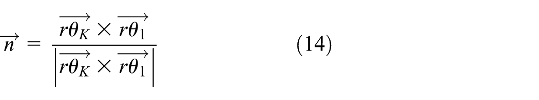
where
On the basis of the second basic homogeneous equation, 17 the principal curvatures of curve-face gear should be satisfied according to the equation

where
The results of equation (15) are

According to the theoretical analyses mentioned above, the geometric parameters, which are needed in the analysis of the principal curvatures of curve-face gear pair, are shown in Table 2.
Geometric parameters of curve-face gear pair.

According to the periodic variation of the structure of the gear pair, the research on tooth 1 to tooth 5 in the half cycle of this gear pair is needed; the tooth numbers of the half cycle of curve gear pair are proposed in Figure 5.

Tooth numbers of curve-face gear pair.
According to equations (13) and (16) and the parameters in Table 2, the relationship between the principal curvatures of this curve-face gear pair and the rotation angle
As shown in Figure 6(a), tooth 1 to tooth 5 are the continuous five teeth of non-circular gear and the two principal curvatures
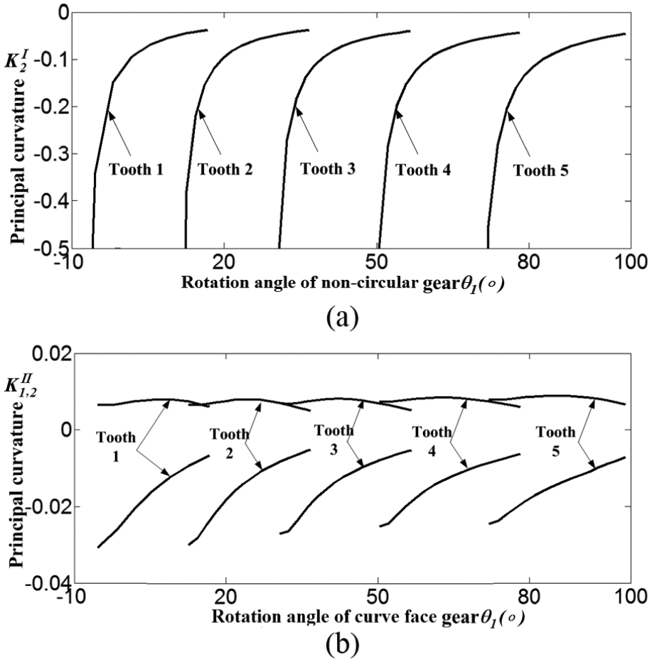
Principal curvatures of gear pair: (a) principal curvatures of non-circular gear and (b) principal curvatures of curve-face gear.
As shown in Figure 6(b), the two principal curvatures
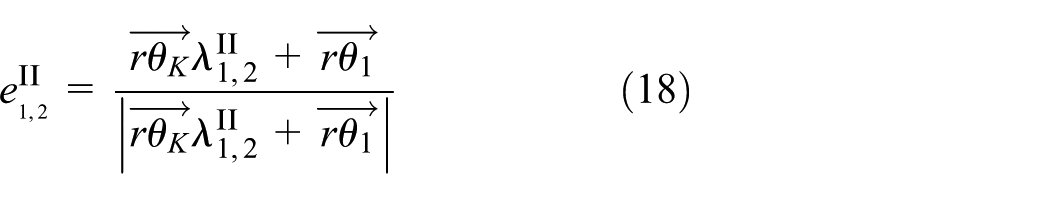
For the better understanding of the directions of principal curvatures, assume that

From equation (17), the parameters
Contact area of curve-face gear pair
With a certain load loaded on the tooth surface of this curve-face gear pair, the contact area can be covered by an ellipse. 17 According to the solution method of Boussinesq problems, the semi-major axis and semi-minor axis of the contact ellipse can be expressed as follows 18

where

where
The area S of contact ellipse can be obtained by the radius of the semi-major and semi-minor axis of the contact ellipse, which can be supported by equation (19) with the following equation

According to equation (19) and the parameters in Table 2, the relationship between the semi-major axis of contact ellipse and the rotation angle
As shown in Figure 7, the semi-major axis of the contact ellipse have the same changing tendency from tooth 1 to tooth 5,which are the continuous five teeth of curve-face gear. The addendum of curve-face gear is in the engagement, and the tooth root of curve-face gear is out of the engagement in the meshing process. With the double-meshing process not been taken into consideration, the semi-major axis of contact ellipse decreases first and then increases with the meshing goes from addendum to the root of the tooth of curve-face gear. The maximum semi-major axis of the contact ellipse is obtained at the addendum and the minimum one is proposed at the tooth root.

The semi-major axis of the contact ellipse.
During the meshing process of practical application of this gear type, the contact ratio of curve-face gear is between 1 and 2, so there are both single-tooth meshing process and double-meshing process. According to the meshing process of normal-face gear pair, the meshing processes at the addendum and the tooth root of curve-face gear are double-meshing process and the meshing process at the middle of the tooth surface of curve-face gear is single-tooth meshing process, so the normal force
According to equation (19) and the parameters that are shown in Table 2, the relationship of the semi-minor axis of contact ellipse and the rotation angle
As shown in Figure 8, for tooth 1 to tooth 5 which are in the half cycle of curve-face gear, the semi-minor axis of contact ellipse has the same changing tendency. With the double-meshing process taken into consideration in the actual meshing process, the semi-minor axis of the contact ellipse will decrease suddenly with the single-tooth meshing process becoming double-meshing process and increase suddenly with the meshing turning into double-meshing process.

Semi-minor axis of the contact ellipse.
According to the gear meshing theory, the direction of the principal curvatures of contact point is the direction of semi-major axis and semi-minor axis of the contact ellipse of curve-face gear. Taking tooth 1 of the half cycle of curve-face gear as an example, the contact point can be established by equation (7), the semi-major axis and semi-minor axis of the contact ellipse can be obtained with equation (19), and the directions of semi-major axis and semi-minor axis of the contact ellipse of curve-face gear can be derived by equation (18). So, the contact path on the surface of tooth 1 can be presented.
As shown in Figure 9, the tooth contact path of this curve-face gear is near the cylindrical surface with radius R = 71.2853 mm. And the semi-major axis of the contact ellipse of curve-face gear will be a little large with the parameters, which are shown in Table 2. The inner radius R1 of curve-face gear is 70 mm and the outer radius R2 is 83 mm, so the tooth contact path concentrates on the inner part of curve-face gear and there may be a partial load phenomenon on the tooth surface of curve-face gear. Taking the practical application into consideration, based on the same inner radius R1, the load should be light enough to avoid the partial load phenomenon on the surface of curve-face gear, and the partial load phenomenon can be avoided by much smaller R1 with appropriate tooth surface modifications.

Contact path of tooth 1 of curve-face gear.
According to equation (21) and the parameters in Table 2, the relationship of contact ellipse with the rotation angle

Contact ellipse areas on the tooth surface of gear pair.
As shown in Figure 10, the contact ellipse areas have the same changing tendency from tooth 1 to tooth 5, which are in the half cycle of curve-face gear. The contact ellipse area increases from the addendum to the root of tooth in the meshing process with the double-meshing process not be taken into consideration. But there will be the sudden change between single-tooth meshing and double-meshing during the practical meshing process, and the contact ellipse area decreases suddenly with the single-tooth meshing process becoming double-meshing process, and the contact ellipse area increases suddenly with the double-meshing process becoming single-tooth meshing process. The contact ellipse area at the addendum of every tooth, which is shown in Figure 10, is minimum with meshing goes from the trough to the peak of the whole tooth surface, while the contact ellipse area at the middle of the surface of every tooth is the maximum.
Analysis of contact stress
Based on the classical Hertz contact theory, during the meshing process of this curve-face gear pair, the contact area on the tooth surface of this gear pair can be deemed as an ellipse region and the maximum contact stress is obtained at the center of the contact ellipse. The maximum contact stress

According to equation (22) and the parameters in Table 2, the relationship of the maximum contact stress
As shown in Figure 11, tooth 1 to tooth 5 are the adjacent five teeth of curve-face gear. The maximum contact stresses at the contact ellipse of curve-face gear have the same changing tendency. With the influence of double-meshing process neglected, the maximum contact stress decreases from the addendum to root with the meshing goes. So, the addendum at every tooth of curve-face gear is easy to wear in the meshing process. With the contact ratio and the double-meshing process into consideration, the maximum tooth contact stress will increase suddenly with the single-tooth meshing process becoming double-meshing process and decrease suddenly with the double-meshing process becoming single-tooth meshing process. And the sudden change in contact stress of curve-face gear pair is an obvious difference between this curve-face gear pair and normal-face gear pair.

Maximum tooth contact stress of gear pair.
Experiment
In order to verify the correctness of the theoretical analysis of tooth contact path, the four-order curve-face gear and the paired two-order non-circular gear are processed by a five-axis computer numerical control (CNC) milling machine, and the curve-face gear drive test bench is built with the help of Chongqing University. The experiment of this curve-face gear pair is shown in Figure 12.

Experimental system of curve-face gear pair.
Adjusting the speed of non-circular gear to 100 r/min by controlling the drive motor with the load torque

Experimental and theoretical torque of the gear pair.
As shown in Figure 13, because of the periodic changes in the additional dynamic load caused by the rotation acceleration of curve-face gear, the friction, and the additional dynamic load of the load motor, the actual load torque of the curve-face gear shaft is around 200 nm with a periodic variation. The absolute error of the experimental torque and the theoretical torque is less than 1.1976 nm (0.6%). After the rolling experiment with a certain load, the tooth contact paths on the surface of tooth 1 to tooth 5 of curve-face gear are shown in Figure 14.
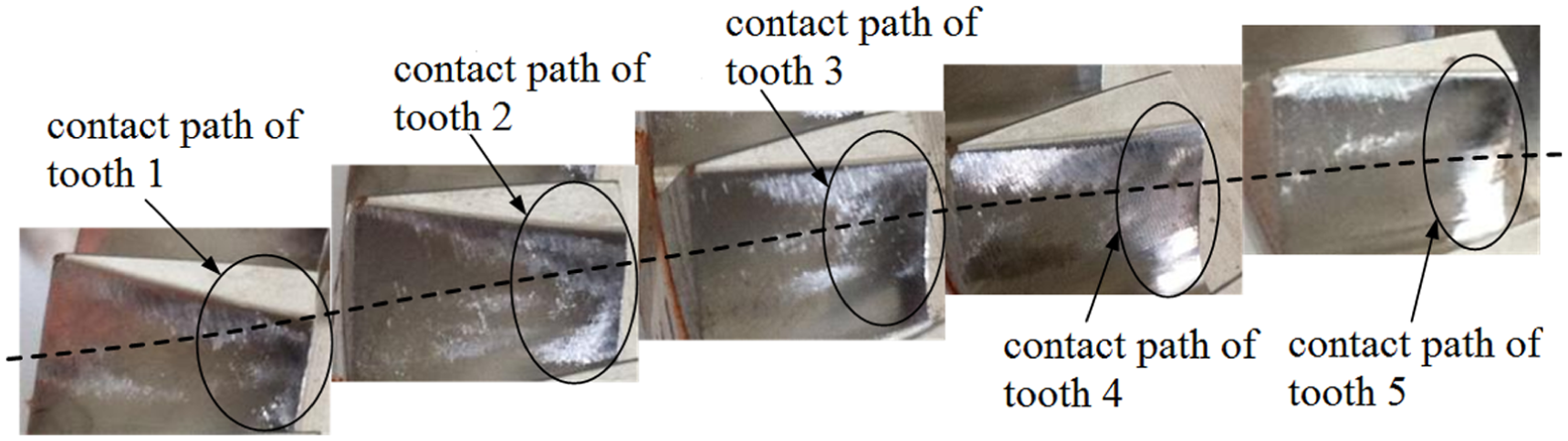
Experimental tooth contact paths of curve-face gear.
As shown in Figure 14, with the load torque T = 200 nm, part of the tooth contact paths of tooth 1 to tooth 5 is located on the outer part of curve-face gear with most of it located on the inner part of curve-face gear, which can be caused by the contact ratio of this curve-face gear pair. This experimental result is affected by the machining error and misalignment of this gear pair. Taken these errors into consideration, Figure 14 shows that the tooth contact paths concentrate on the inner part of curve-face gear and the addendums of curve-face gear wear seriously as theoretical analysis and the experimental results are consistent.
Conclusion
The LTCA of curve-face gear pair is an important part for the design of curve-face gear pair, and it is also one of the most important theoretical bases for the application of the gear pair. According to the LTCA of curve-face gear pair which is shown in sections “The model of curve-face gear pair” to section “Experiment,” the following conclusions can be proposed.
The larger principal curvature
The instantaneous tooth contact area of the curve-face gear is an ellipse region. The contact ellipse is located on the inner part of curve-face gear and its center is near the cylindrical surface, which is the surface of the pitch curve of curve-face gear, and it can be improved with appropriate tooth surface modifications. The semi-major axis of contact ellipse, which is obtained at the addendum and the middle of the tooth surface of curve-face gear, is larger than the semi-major axis of contact ellipse, which is obtained at the tooth root of curve-face gear. The contact ellipse area at the addendum is the minimum, while the contact ellipse area at the middle of the tooth surface is the maximum.
The maximum contact stress of each tooth of curve-face gear decreases from the addendum to root and the maximum contact stresses increase from the trough to the crest of the tooth of curve-face gear.
The experimental tooth contact paths of curve-face gear are presented by the rolling experiment of this gear pair. The calculation method of LTCA of curve-face gear pair is verified by the experimental results.
Footnotes
Academic Editor: Hiroshi Noguchi
Declaration of conflicting interests
The author(s) declared no potential conflicts of interest with respect to the research, authorship, and/or publication of this article.
Funding
The author(s) disclosed receipt of the following financial support for the research, authorship, and/or publication of this article: The authors would like to appreciate the supports from the National Natural Science Foundation of China (51275537 and 51675060).