
Abstract
A tilt compensation system is presented in this article to compensate the tilt in the translation micromirror used in miniaturized Fourier transform infrared spectrometers. This compensation system can not only be used for the micromirror tested in this article but also be applicable to any translation micromirror with undesired tilt about one fixed axis. The compensation system consists of only a compensation micromirror and a reflecting mirror. The compensation micromirror rotates an angle of the same magnitude and same direction as the translation micromirror’s tilt. The compensation micromirror has its rotation axis parallel to the tilting axis of the translation micromirror, which is identified using a position sensing detector–based setup introduced in the article. Experimental results show the tilt of the translation micromirror can be compensated to 0.026° from the original tilt of 0.24°.
Introduction
Benefiting from the microelectromechanical systems (MEMS) fabrication technology, 1 the translation micromirror2–8 has been used in Michelson interferometer–based9–13 miniaturized Fourier transform infrared spectrometers (FTIRs).14–18 However, the undesired tilt existing in the translation affects the quality of the generated interference pattern. As shown in Figure 1, the reflected beams from the fixed and translation mirror cannot combine perfectly if the translation mirror tilts during the translation. As a result, the resolution of the generated spectrum will be degraded. To overcome the tilt, many techniques have been developed. For example, (1) air bearing or the rolling elements linear mechanical bearing19–21 are used in conventional macrotranslation mirror in Michelson interferometer to ensure the tilt as small as 0.008°. This method requires complex structure (sealed moving bearing, guide rail, motors, etc.) and also increases the size;20,21 (2) using dynamic compensation system,22,23 the position of the translation mirror can be adjusted when various voltages are applied on the multiple actuators; (c) instead of translation mirror, using optical elements, such as corner cube reflectors (CCR) and cat’s eye mirror;24–30 and (d) using mirror-tilt-insensitive system which is realized by a double-sided plane mirror.31–33 Using the control system–based method, open-loop and closed-loop control systems are proposed by Xie’s group in recent years to reduce the size and improve the accuracy of the FTIRs, in which the tilt of micromirror is reduced to 0.004° (± 0.002°) and 0.003° (± 0.0015°), respectively. This method requires multiple actuators16,34,35 to adjust in all directions through the feedback signal to achieve tilt correction, which are generally not available in micromirrors. Moreover, this method requires additional light source, beam splitter, and photo detectors to construct the feedback loop which increase the cost and size. The tilting correction method proposed in this article has the advantages of lower cost, smaller size, and simpler structure.
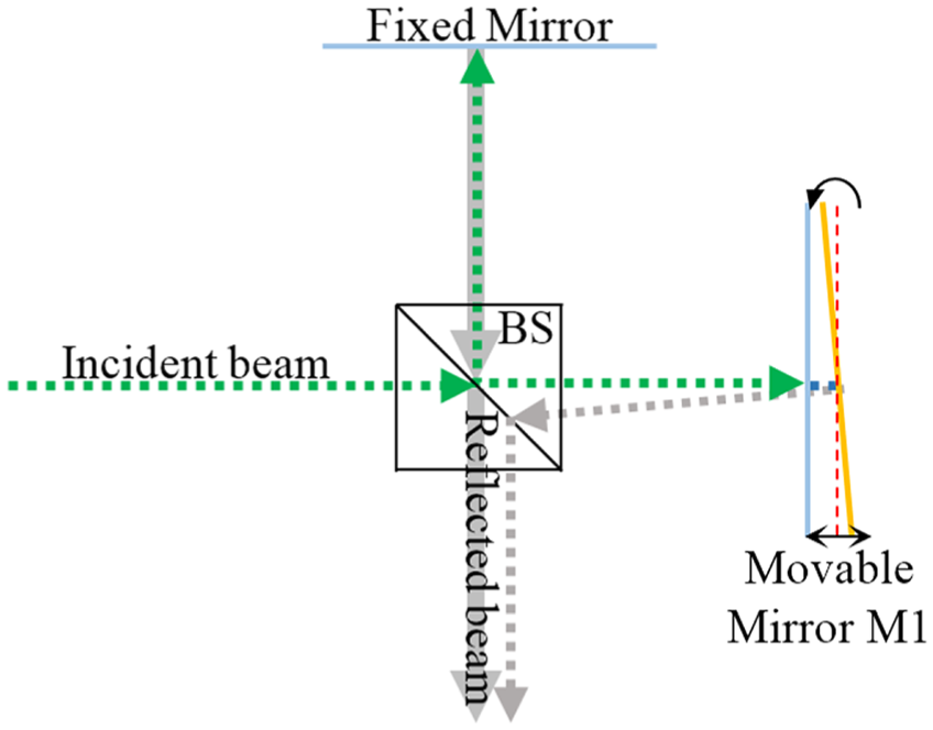
Tilt exists in conventional Michelson interferometer.
The tilt can be caused by multiple reasons, for example, the fabrication process variation leads to discrepancies between actuators; 16 and the manufacturing/assembly error lead to the uneven magnetic fields applied to micromirror’s symmetric part.6,8 Since those undesired tilt causes are normally constant/unchanged during the translation of the mirror, the tilt is normally about a fixed axis. This article proposes a tilt compensation system to compensate for the translation micromirror’s tilt, which is about a fixed axis. The compensation system consists of only a compensation micromirror and a reflector, as well as the calibration of the tilt versus translation. No extra complex optical system or closed-loop control system is needed.
The article is organized as follows: the design of the compensation system is introduced in section “Tilt compensation system,” the experiment is introduced in section “Experiments,” and conclusions are summarized in section “Conclusion.”
Tilt compensation system
Working principle
The compensation system includes a one-dimensional (1D) compensation micromirror M2 36 and a reflecting mirror M3 to correct the tilt of the translation mirror M1. The tilting of M1 follows a constant and fixed manner, that is, tilting about one fixed axis, and the tilt versus the translation/driving current has a constant/fixed relation which can be calibrated. As shown in Figure 2(a), the compensation is achieved through M2 to rotate the same angle γ in the same direction as the tilt of M1. The compensated beam is reflected back by M3 to the beam splitter to generate the inference pattern with the beam from the fix mirror. The rotation axes of mirrors M1and M2 must be parallel. The beam from M2 needs to be injected vertically to M3. Otherwise, the beam reflected from M3 cannot return to M2 along the incoming path. As a special case, as shown in Figure 2(b), when M3 is perpendicular to the fixed mirror and M2 is parallel to M1, circular fringes are generated, similar in the traditional Michelson interferometer. 37 Only the straight fringes are discussed in this article.

The tilt compensation system: (a) M3 is angled with the fixed mirror and (b) M3 is perpendicular to the fixed mirror.
The interference fringe width is defined as w when no voltage is applied. After applying driving voltage, M1 translates with undesired tilt. Due to the tilt, fringe width changes. M2 rotates to compensate for the tilt of M1 to restore the original fringe width w. The new fringe width is w′. If the tilt is completely compensated, w′ is equal to w.
The following definitions are used in this article:
θo is the angle between two beams reflected from M3 and the fixed mirror, respectively, when neither M1 nor M2 is driven;
θM1 is the angle between two beams reflected from M3 and the fixed mirror, respectively, when only M1 is driven;
θM1_M2 is the angle between two beams reflected from M3 and the fixed mirror, respectively, when both M1 and M2 are driven to compensate the M1’s tilt.
The relationship between the fringe width w and θ can be obtained using the equation below 38
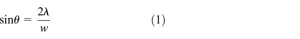
where λ is the wavelength of the beam.
Calibration process
To achieve the compensation, the tilting axis of M1 needs to be determined first in order to position the rotation axis of M2 parallel to M1’s tilting axis. The M1’s tilting axis is determined as follows. A laser beam is shot to the M1 and reflected onto the screen of a PSD (position sensing detector), as shown in Figure 3. If the M1’s tilting axis is not parallel to the Z-axis, the trajectory on the PSD is not horizontal and parallel to the X-axis, as shown in Figure 3(a). Rotate M1 about Y-axis until its trajectory is horizontal, at which the trajectory on PSD is caused by the constructive superposition of the tilt and the translation of M1. Thus, the M1’s tilting axis is parallel to the Z-axis. M2 is then positioned with its rotation axis parallel to M1’s tilting axis.

Determination of tilting axis: (a) micromirror travels on the Y-axis with tilt along a rotation axis other than the Z-axis and (b) with tilting along the Z-axis.
To ensure M2 rotates the same angle with the tilt of M1, a trial-and-error method is used to find the current applied to M2. The detailed steps are as follows: (1) an interference pattern is obtained as a reference after setting all the mirrors; (2) M1 displaces with the tilt after a static current is applied, which leads to the interference pattern change; and (3) multiple interference patterns are generated by applying a series of currents on M2, then the one with the fringe width closest to the reference fringe width is chosen and the corresponding current is recorded. This process is repeated to find the compensation currents to M2 at different displacements of M1. After that, a linear interpolation method is used to determine all currents to M2 to compensate for all tilts of M1. A table is generated to record each displacement of M1 and the corresponding currents to M1 and M2. Using the table, the data can be input directly in the open-loop control in the real-time operation.
Accuracy analysis
A lens is used to magnify the fringe image. Edge of fringe is not very sharp on the interference pattern, which leads to the fringe width variation of ±d. Then, the compensation accuracy, the difference between the initial angle θ and the compensated angle θ′, can be expressed below (θ is small here)
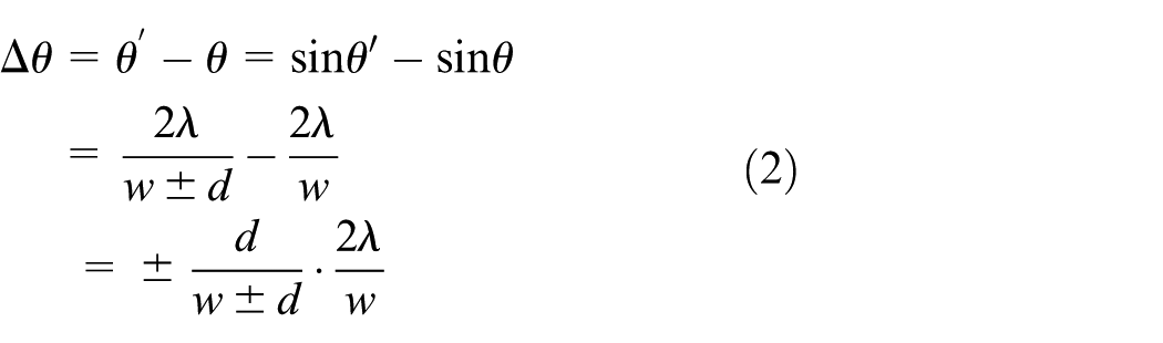
where λ is 532 nm, w is 214.3 µm, and d is 14.3 µm; therefore, the Δθ is ±3.55e–4 rad or ±0.02°.
Experiments
Platform setup
Michelson interferometer with the tilt compensation system is shown in Figure 4(a), which includes a laser (<5 mW, 532 nm), a beam splitter, a fixed mirror, and the tilt compensation system. The compensation system consists of Lorentz force rotation mirror M2 36 and a reflecting mirror M3. Large rotation and reflecting mirrors are used in the experiment, for example, 1 in in diameter, for easy observation and adjustment, but both of them can be replaced by much smaller mirrors. Figure 4(b) shows M1, M2 and M3. M1 travels under the magnetic field generated by the electromagnet underneath it, as shown in Figure 4(c). M2 is driven by the Lorentz force applied on the flexible printed circuit board (FPCB) micromirror. 36 The Lorentz force is generated by two permanent magnets on the side when the current passes through the magnetic field, as shown in Figure 4(d). M1 is placed on a rotation stage, which is mounted on a two-dimensional (2D) linear stage, thus M1 can be rotated in Y-axis and moved in the XY plane. M2 is mounted with its rotating axis perpendicular to the table on a 1D linear stage 39 to move up and down. Therefore, the relative position between M1 and M2 can be adjusted to make the tilting axis of M1 parallel to the rotation axis of M2. The laser, the fixed mirror, and M3 are mounted on the tip of the tilt adjustment stages to ensure the reflected beam can be combined at the beam splitter. All the parts including the beam splitter and the concave lens, which magnifies the interference pattern for observation, are assembled on an optical bench. Since multiple stages are used to adjust the positions of the mirrors in the calibration stage, the size of the experiment setup is large, but the real package will be much smaller after the calibration is completed and then stages are no longer needed.

Michelson interferometer with a tilt compensation system: (a) top view of the experimental platform, (b) detailed view of tilt compensation system, (c) detailed view of the translation mirror M1, and (d) detailed view of the 1D compensation mirror M2.
Determine the tilting axis
As introduced in section “Calibration process,” the tilting axis of M1 can be found through monitoring the change of the trajectory on the PSD, as shown in Figure 5. Figure 5(a) shows M1 is on a rotation stage 40 which rotates along Y-axis and M2 and a PSD which is vertically placed on the table. When a laser beam is reflected by the mirror to the PSD, M1 is rotated until the minimum voltage (i.e. with the minimum identifiable amplitude) is found in the oscilloscope in the vertical direction of the PSD. For example, 10 mV is observed on the oscilloscope (the blue line in Figure 5(b)) when M1 travels about 100 µm. This is the minimum voltage found on the oscilloscope after M1 rotates 360° along the Y-axis, which means the tilting axis of M1 is approximately perpendicular to the table at this position.
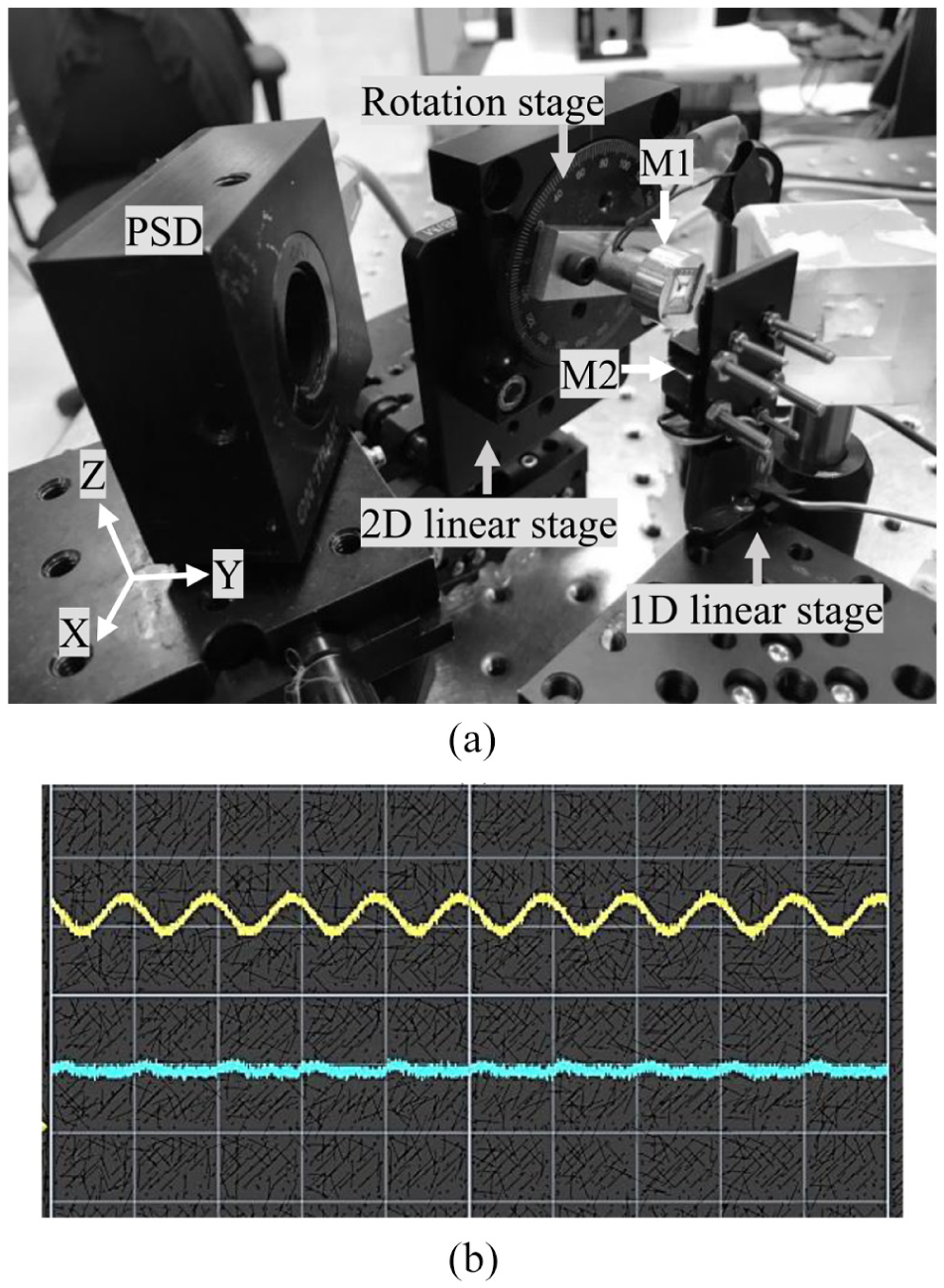
Determine the tilting axis using the PSD and the oscilloscope: (a) experiment setup and (b) the minimum voltage (<10 mV) is observed when M1 translates by 100 µm.
Tilt compensation by M2
After all components are assembled, an interference pattern with 70× magnification generated by the reflected beams from the fixed mirror and M3 is shown on the screen, where a 2-mm grid paper is used, as shown in Figure 6. A reference pattern is measured, as an example shown in Figure 6(a), in which four fringes are on the screen at the starting position without applying current. The distance between two adjacent dark or bright stripes is measured.

Magnified interference pattern on the screen: (a) first reference fringes, (b) misaligned under 30 µm displacement without compensation, (c) interference pattern when M1 travels 30 µm with compensation, (d) second reference fringes, (e) only the spot from the fixed mirror is shown on the screen due to no compensation, and (f) interference pattern when M1 travels over 100 µm with compensation.
The current is applied to M1 and the fringes are changed due to the tilt. For example, after M1 travels 30 µm, the interference pattern on the screen is misaligned, as shown in Figure 6(b). To compensate it, a trial-and-error method is used to find the required current on M2. A series of currents with 1 mA incremental every 10 ms are applied on it. Among the generated interference patterns under different currents, the one closest to the reference is identified and the correspondent current is recorded. For example, when M1 travels 30 µm, the closest pattern is found when 15 mA current is applied to M2, as shown in Figure 6(c).
Because of the limitation of M1, 6 that is, 3–4 µm starting position variation even after 30 min pre-oscillation, the interference pattern cannot return to the starting position completely. Therefore, the initial interference pattern needs to be measured again as the new reference for each independent experiment. For example, as shown in Figure 6(d)–(f), when M1 travels 100 µm, the new reference is in Figure 6(d) and the 45 mA current is found on M2. Using this method, 12 equal incremented currents are applied to M1 until the rated current is reached. The corresponding currents to M2 are also obtained and recorded.
Error analysis
According to equation (1), the initial fringe width after magnification is 16 mm as shown in Figure 7, so the angle θo is 0.267°. When 67 mA current is applied on the translation micromirror, the fringe width changes to 9 mm and the corresponding angle θM1 is 0.474°. The difference is 0.207°, which is the optical angle. The mechanical angle is 0.103°, very close to 0.1°, which is the measurement result using Zygo optical profile machine under the same current. Equation (1) is experimentally verified. The fringe width measurement error exists as explained in Figure 8. For example, five widths (12, 13, 14, 15, and 16 mm) are used to measure one example fringe width as shown in Figure 8. Because the edge of the fringe is not sharp, 13, 14, and 15 mm could be the fringe width while 12 or 16 mm is not the width since they are either too narrow or too wide. Thus, this example fringe width measurement error is ±1 mm based on the magnified fringe pattern. Thus, the corresponding angle range is 0.08°–0.13°. Due to the variation in the starting position of M1, 6 the fringe width varies in each measurement in the range of 185.7–228.6 µm. As shown in Figure 9, Δθ for 12 different points is calculated, among which 0.026° is the maximum value. By comparing with the tilt of M1 measured in Zygo three-dimensional (3D) profiler which is 0.24°, 6 the tilt has significantly reduced which represents the capability of the compensation system.
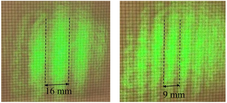
Interference fringe change due to the tilt of M1.
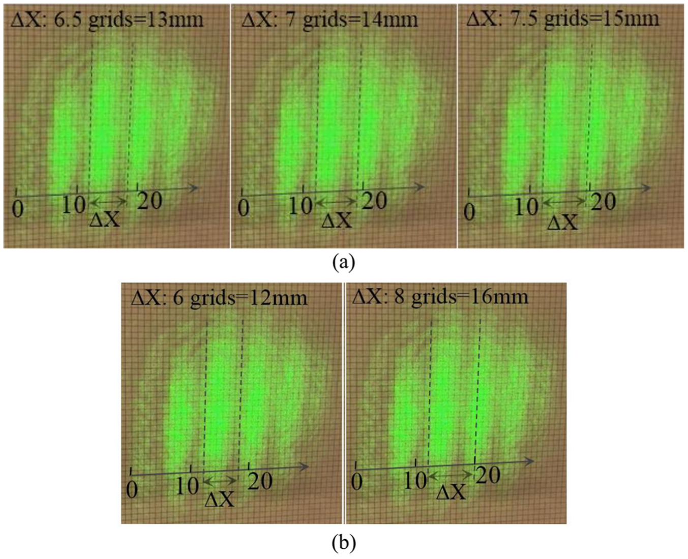
Fringe width measurement: (a) 13, 14, and 15 mm as the fringe width and (b) 12 and 16 mm as the fringe width.

Angle difference Δθ.
Conclusion
A tilt compensation system is proposed for translation micromirror used in miniaturized FTIRs in this article. The tilt to be compensated is about one fixed axis. By comparing with other compensating systems, it has smaller size, simpler structure, and lower cost. The proposed tilting compensation technology can be used not only for the translation micromirror developed by our group 6 but also for other translation micromirrors as long as the micromirror’s tilting is about one fixed axis. The compensation micromirror rotates the angle of the same magnitude and same direction of the translation micromirror’s tilt. In the experiment, a translation micromirror, 6 a 1D Lorenz force magnetic rotation micromirror, 36 and a reflecting mirror form the compensation system. And its performance in a Michelson interferometer is tested. It proves that the designed compensation system can compensate the tilt to 0.026° from the original 0.24°.
Footnotes
Handling Editor: Long Cheng
Declaration of conflicting interests
The author(s) declared no potential conflicts of interest with respect to the research, authorship, and/or publication of this article.
Funding
The author(s) received no financial support for the research, authorship, and/or publication of this article.