
Abstract
In this article, three types of high-speed mine submersible pumps were designed and experimented. During the reliability performance test, the axial thrust balancing device of GFQ150-700 was overloaded and damaged due to an unsuitable designed value of axial thrust. The designed hydraulic axial thrust with the actual value is compared in this article, and the reason for axial thrust deviation is discussed. Results show that axial thrust of the theoretical calculation is close to the numerical simulation value at a certain extent. GFQ100-1000 obtains the maximum theoretical axial thrust, while the maximum simulated value is produced in GFQ150-700, and that is corroborated by experiments. The axial blade force is related to the pump stage and area differences between the blade suction and pressure surface. Due to the increasing stage in GFQ100-1000, the axial blade force increases to a remarkable value in an opposite direction with respect to GFQ150-700. The opposite blade force offsetting other hydraulic forces in GFQ100-1000 is responsible for the maximum hydraulic axial thrust emerges in GFQ150-700 instead of GFQ100-1000.
Keywords
Introduction
The prevention of mine water disaster is one of the important issues for the safety and efficient production of coal mine, and the level of prevention depends on water control technology and equipment. 1 When mine water inrush happens, the capacity of instantaneous gushing water will be more than the maximum drainage capacity of the pump house, which will cause flooding accident. High-power submersible pump is the major equipment of coal mine productive drainage rescue. 2 With high flow rate and head, high-power submersible pump can quickly drain the water in the mine. 3 Due to the heavy and large size of the pump and the limitation of the mine shaft cage size and underground space, it will extend the rescue time if the pump is split and then reassembled underground.4,5 Besides, frequency technology is applied in high-speed mining submersible pumps to improve the speed, and it leads to the strict requirement of the pump with high head, small size and low weight. Moreover, the pump is required to be quickly installment, which is meaningful to the emergency rescue and rapid recovery of production.
Currently, computational fluid dynamics (CFD), a major method to investigate the internal flow field of centrifugal pumps, has been widely used to predict the performance of pumps and research the internal related problems.6,7 Many turbulence models could be chosen according to the calculation model in CFD. 8 The standard k-ϵ model is very suitable for submersible pump, and the predictive performance results are consistent with the test result. 9 Considered the influence of flow in wear ring clearance, it is better to calculate the model pump with the wear ring clearance. 10 Some physical quantities, which cannot be measured in the flow field normally, such as radial force, can be easily extracted in the numerical simulation results.11,12 Also, it can be accurately calculated to analyze the internal physical quantities in high-speed centrifugal pumps with inducer. 13
High-speed mine submersible pump belongs to high-power pump, which axial thrust balance study is one of the key issues to ensure the normal running of the pump. Axial thrust of pump can be obtained by empirical method, test method, and theoretical calculation. Empirical method and theoretical calculation are simple, but the accuracy and applicability are poor and not universal. Test method is more accurate but the operation is complicated, and it needs to change the unit shaft structure connected to the force measurement device to complete the test.14,15 At the same time, according to the principle of theoretical calculation, the cover force can be estimated by arranging multiple points to test pressure near the cover.16,17 In the impeller structure, the axial force can be effectively reduced with seal ring and balance hole, which can also be reflected in the numerical simulation results. 18 A pressure loss coefficient is added to the theoretical formula to calculate the leaky pressure of the cover. The pressure loss coefficient is verified by the cover force obtained by experiments. Both of these approaches could improve the accuracy of empirical method and theoretical calculation. 19 On the basis of verification accuracy of external characteristic experiment, it is feasible to deduce the size and changes of other axial force component in the pump. 20
In general, the methods for obtaining axial thrust mainly include theoretical calculations, numerical simulations, and experiments. The objective of this study is to investigate the axial thrust deviation between the theory and experiment for high-speed mine submersible pump. The case study consists of three different types of high-speed mine submersible pump consisting of the same motor and three pump sections. The theoretical formula was applied to calculate and predict the size of the main axial thrust component during the design process. The numerical simulation was applied to extract the axial thrust on the impeller surface. Finally, the reason is analyzed from the influence of each axial thrust component on the overall axial thrust.
Case study and axial thrust design
Physical model
In this article, the test models of three high-speed mine submersible pump unit specifications are as follows: GFQ200-500, GFQ150-700, and GFQ100-1000; the mark GFQ200-500 means that the nominal flow rate is Qd = 200 m3/h of this high-speed mine submersible pump and the designed head is Hd = 500 m. The designed flow rate and the designed head of the other two specifications are Qd = 150, 100 m3/h, Hd = 700, 1000 m, respectively. The rated power of the motor Pd = 900 kW. GFQ200-500 and GFQ150-700 are the single-stage impeller structures, and GFQ100-1000 is the two-stage impeller structure. The specific speeds ns of three models are 48.8, 33, and 35 (single-stage impeller). The heads of corresponding inducers are 15.7, 11.7, and 7.7 m. Three units with different models use the same motor to meet the parameters of the requirements of different units by replacing the corresponding part of the pump parts to achieve the conversion of various units. The rotating speed of high-speed mine submersible pump unit n is 5900 r/min.
The high-speed mine submersible pump unit adopts the pump under the motor structure. The motor adopts frequency conversion wet structure, and the motor and pump part were connected by the shaft directly. The water was drawn into interior of the unit from the filter on the outside of the base, in turn through the inducer, the impeller, and the guide vane, then through the access of the motor housing and outer cylinder, and finally, flows out from the top of the pump cover. The total length of the pump is within 3600 mm, and the diameter is within 1200 mm. There was a thrust plate in the top of the motor, and the thrust plates are, respectively, connected with the upper thrust bearing and the lower thrust bearing to form the thrust institution. The upper and lower friction surfaces form the liquid film to resist the axial thrust force and bear the axial thrust in the two directions of the pump. The thrust institution was designed to bear 1.1 × 10⁴ N axial thrust. The thrust plate with flow hole can function like impeller, as the power of the cooling circulation. Figure 1 shows the structure of mine submersible pump unit with single-stage impeller structure. In the two-stage impeller structure, two impellers also were located in the middle between the body and the base. The hydraulic part and thrust institution were partially enlarged.
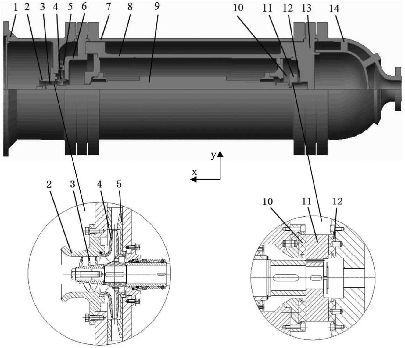
Structure of the high-speed mine submersible pump.
Theoretical calculation of axial thrust
The high-speed mine submersible pump belongs to the submersible pump. In the theoretical calculation of submersible pump axial thrust, it is generally believed that each axial thrust component to function on rotor and the generating factors mainly concludes the following:
Cover plate force F1: the axial thrust generates from the asymmetry of front and rear impeller cover plate compression area. This force is directed to the inlet of the impeller.
Dynamic reaction force T2: the reaction force generates from the fluid to the impeller in the flow-path. This force is directed to the back of the impeller.
Shaft head force: the axial thrust generates from the unbalance of shaft table, shaft end and other end compression surface (when the high-speed mine submersible pump is running, the motor side of the shaft is located at the inlet of the thrust plate, and the pump side of the shaft is located at the inlet of the impeller. The pressure on the inlet is low and the size is similar, so the shaft head force is negligible).
Rotor gravity T4: the axial thrust generates from the weight of the vertical rotor. This force is directed to the +x.
The axial thrust generates from the change in operating conditions.
The resultant force of each component is the total axial thrust of the entire rotor system. The size of the axial thrust caused by each factor is different. This paper mainly considers the three axial thrusts of cover force, dynamic reaction force, and rotor gravity. The positive direction is the inlet of the impeller, that is directed to the +x. The thrust institution could withstand a certain degree of axial thrust in running. During the design, the axial thrust size was predicted by theoretical calculation, and it is necessary to control it within a certain safe range. The axial thrust balance of the high-speed mine submersible pump is mainly solved by the wear ring with balance hole and the thrust institution. However, the axial thrust still exists due to the difference between the theoretical calculation and the actual running.
Assume that the flow in the chamber on both sides of the cover is a no leakage flow. The liquid rotates at half the angular speed of the impeller. Front and rear impeller cover plate were similar to the disk wall to drive the liquid rotation in the chamber on both sides. The pressure distributions in the chamber on both sides are in accordance with the parabolic law. 21 When the impeller does not adopt the wear ring and balance hole to reduce the axial thrust, the original cover force A1 is

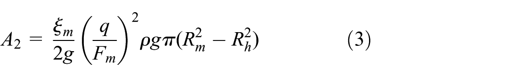
When the impeller adopts the wear ring and the balance hole, the leakage flow rate q of balance hole could be obtained by formula (2). Due to the resistance loss when the liquid flows through the wear ring clearance, the pressure of the liquid below the seal ring drops a lot. The axial thrust acting on the rear cover is reduced. The balance effect could be equated to the balance force A2

At this time the cover force F1 after the balance is

High-speed mine submersible pump adopted centrifugal impeller. The flow direction of the medium was changed by a force from the impeller structure. At the same time, the medium also gives the impeller a reaction force which was in the opposite direction and the same size to this force. Based on momentum theorem, the dynamic reaction force T2 is

An inducer is used in the high-speed mine submersible pump unit. The inducer blade force is also the axial thrust component. Inducer blade force F4 is the axial thrust from inducer blade surface, and it cannot be calculated directly by formula. The theoretical calculation of hydraulic axial thrust extracted from numerical simulations would be presented in the posterior part of the article. The hydraulic axial thrust F5 is the total thrust of high-speed submersible pump unit rotor from the medium in running

Rotor gravity T4

The total axial thrust of the unit rotor F

Based on the current case study and experience of centrifugal pump axial thrust, axial thrust of centrifugal pumps rotor hydraulic components has a major relationship with the internal pressure. The head is the highest at the low flow rate condition leading to large axial thrust force in this case. In the high-speed mine submersible pump test, 0.5Q is the first flow rate condition. It is assumed that the axial thrust of the unit at this flow rate condition is the maximum within the measuring range. The problem occurred at this flow rate condition in the first test of the GFQ150-700 unit.
The theoretical calculation of axial thrust could not be used to calculate the axial thrust at non-designed flow conditions. In normal experiences, the axial thrust reduction trend is similar between the same types of impeller. In this article, the axial thrust calculation results at the design flow rate condition could still be used for reference and analysis.
The total axial thrust and the components of the three high-speed mine submersible pump units are shown in Table 1; the result of GFQ100-1000 is the axial thrust superimposed results of two-stage impellers.
Axial thrust of high-speed mine submersible pump.

As shown in the theoretical results, the cover force is the most important axial thrust component when the impeller is not balanced. It is effective to balance the cover force by setting the wear ring with balance hole on the impeller, but the return flow from the wear ring and the balance hole to the impeller inlet has a greater impact on the pump efficiency. The sizes of wear ring and balance holes should be reduced as much as possible, and it is need to ensure the total axial thrust does not exceed the safety value of the thrust institution. The cover force is still the main component of the hydraulic axial thrust after the balance. The rotor gravity becomes the largest axial thrust component. The axial thrust value of GFQ200-500 unit is the smallest of the three pumps, GFQ100-1000 units is the largest. Taking into the influence of flow rate account, a certain margin factor is applied for safety, and the thrust institution design uses about 1.6 times as the safety factor on the basis of the maximum axial thrust of theoretical calculation at design flow rate condition. Finally, the designed thrust institution could withstand up to 1.1 × 10⁴ N axial thrust to ensure the normal operation of the unit.
Test and problem generation
Test setup
Test of high-speed mine submersible pump unit was conducted in an open test rig, and the diagram of test system and the test site condition is shown in Figure 2. The pump unit was submerged in the water pool under the pilot plant laboratory. The pump cover was connected and fixed to the ground outlet pipe by the straight pipe. Working frequency electric power supply was accessed to the frequency converter. The frequency conversion of frequency converter was inputted in high-speed mine submersible pump unit to achieve the pump running at 100 Hz frequency, that is, the speed reached 5900 r/min. The flow rate was controlled by adjusting the valve opening of outlet pipe. The pressure sensor is used to measure the pressure of outlet part. The electromagnetic flowmeter was used in the flow rate measuring on the pipe after the electric valve. The speed sensor was tied to the outer wall of the motor to measure the motor slip rate, then to calculate the actual motor speed. Finally, the main measurement signals were collected in the signal acquisition instrument of control room.

Test of high-speed mine submersible pump: (a) experimental principle and system; (b) connection of pump on site.
Test result
The test starts with a low frequency then gradually rises to 50 Hz. First of all, according to the progress of the completion of hydraulic component parts, the tests of GFQ200-500 and GFQ100-1000 units were first carried out. The two units were stable in the test, and experimental data were successfully collected. Disassembly inspection shows that thrust institution was intact and no obvious scratch was observed. Finally, the test of GFQ150-700 unit was conducted after assembly. When the frequency increases to 100 Hz, the high-speed mine submersible pump unit run for a short time at 0.5 times designed flow rate condition, suddenly, the current increases over the safe current leading to the frequency inverter stopping. The unit could not run stably and properly when it starts again. The test dismantling situation is shown in Figure 3, and the lower surface of thrust plate and the lower thrust bearing were severely worn. Scratch on the upper surface of the thrust plate was not obvious. It means that the downward axial thrust of the pump is too large, and the friction surface was destroyed and the contact surface of thrust institution was severely worn during running. Transformation program was proposed to increase the thrust plate and thrust bearing diameter. After the GFQ150-700 unit was improved, the test was completed successfully and thrust institution was intact shown in disassembly inspection. Damage of the original thrust institution in the test shows that the unit’s axial thrust exceeded the axial thrust bearing limit of the original thrust institution. The failure occurred in the GFQ150-700 test showed that the GFQ150-700 unit produced the largest axial thrust. These two phenomena do not match the axial thrust result of theoretical calculation during the design process, so more deep analysis is needed.

Test dismantling situation: (a) upper surface of thrust plate, (b) lower surface of thrust plate, and (c) surface of lower thrust bearing.
Numerical simulation
Calculation model
CFD method was applied to find the reason of the damage of GFQ150-700 unit .Three-dimensional model of the main flow passage components in high-speed mine submersible pump are built using Pro/E. The whole computational domain includes 12 main parts, namely, foundation chamber and outlet part (Lout/D1¼3), impeller, guide vane, inducer, front chamber and back chamber, the wear ring clearance and impeller balance hole, middle section chamber, outer cylinder chamber, channel of casing cover, In addition, the two-stage impeller structure also includes the anti-vane after the first-stage guide vane. Figure 4 presents the internal flow computation domain.

The whole internal flow computational domain.
Mesh generation
The radial clearance size of the wear ring is 0.25 mm. The mesh uses structured mesh, and it is generated for the computational domain by ANSYS-ICEM software, which has better convergence characteristic in numerical simulation. The size of mesh depends on the size of each model. The boundary layers are created to ensure the y+ value in a reasonable range near the solid walls. 22 The y+ value of the main mesh near the wall is less than 100. During the numerical simulation of the GFQ200-500, this article checks the independence of the mesh. It gives the appropriate number of meshes that has no significant effect on the numerical simulation results. The mesh element of each high-speed mine submersible pump model, namely, GFQ200-500, GFQ150-700, and GFQ100-1000, is 4,215,572, 3,849,180, and 5,353,632, respectively. Figure 5 presents the generated mesh of partial computation domain.

Structured mesh of the computation domain: (a) impeller mesh, (b) back chamber mesh, and (c) guide vane mesh.
Setting parameters
The commercial ANSYS-CFX software is used to calculate the internal flow in the pump unit. The calculation type is steady simulation. The turbulent model is standard k-ϵ model, and the accuracy has been validated in many reported researches. This article compares the calculation of several turbulence models in the GFQ 200-500’s numerical simulation. The agreement between the results and experimental data also illustrates this situation. The total pressure p = 1 atm is set as the inlet boundary condition. The mass flow rate outlet is selected for the outlet boundary condition. All the physical walls of the pump are set as nonslip walls. The interface adopts the general grid interface (GGI) mesh connection, and the simulation is the unsteady flow situation, the interface of static domain, and rotating domain was set to “Frozen Rotor” option. The convergence precision is set as 3 × 10⁻⁵, which is enough to ensure the accuracy of results. By changing the outlet mass flow rate, the predicted performance of the pump could be obtained. 23
Numerical method validations
Figure 6 shows the investigated pump performance data comparison of GFQ200-500, GFQ150-700, and GFQ100-1000 high-speed mine submersible pump units between experimental and numerical results including H/Hd-Q/Qd, P/Pd-Q/Qd, and η-Q/Qd curves. It can be seen from the head curve that the heads of numerical simulation are slightly higher than the experimental heads. The numerical predicted pump performance heads are in accordance with those of experimental data near the nominal flow rate. The relative errors of the three units are about 2%, 2.5%, and 2.5%. The maximum relative error of predicted head to experimental data is below 4% in the whole flow rate condition range, respectively. It can be seen from the efficiency curve that the efficiency of simulation is slightly higher than the test, and the maximum relative errors of the three units were below 5%, 6%, and 8%. The numerical predicted unit’s shaft powers are slightly higher than the test, and the maximum relative errors of the three units are below 4%, 6%, and 7%. The relative errors of the efficiency curve and the shaft power curve are slightly larger. Part of the reason is that the numerical simulation does not considering bearing friction and other mechanical losses. Considering the loss of mechanical losses and other losses in the numerical predicted shaft power, simulation efficiency is reduced, and it is close to the test results. In general, the numerical predicted pump performance curve is consistent with the experimental data, especially in the vicinity of the nominal flow rate conditions. The comparison of the performance between the numerical prediction and the experiment shows that the k-ϵ turbulence model has good applicability in describing the fully developed turbulent flow.24,25 On the basis of verification accuracy of the pump performance, it is feasible to deduce the size and changes of other axial force component in the pump. 20 The method can be used for the analysis of axial thrust.
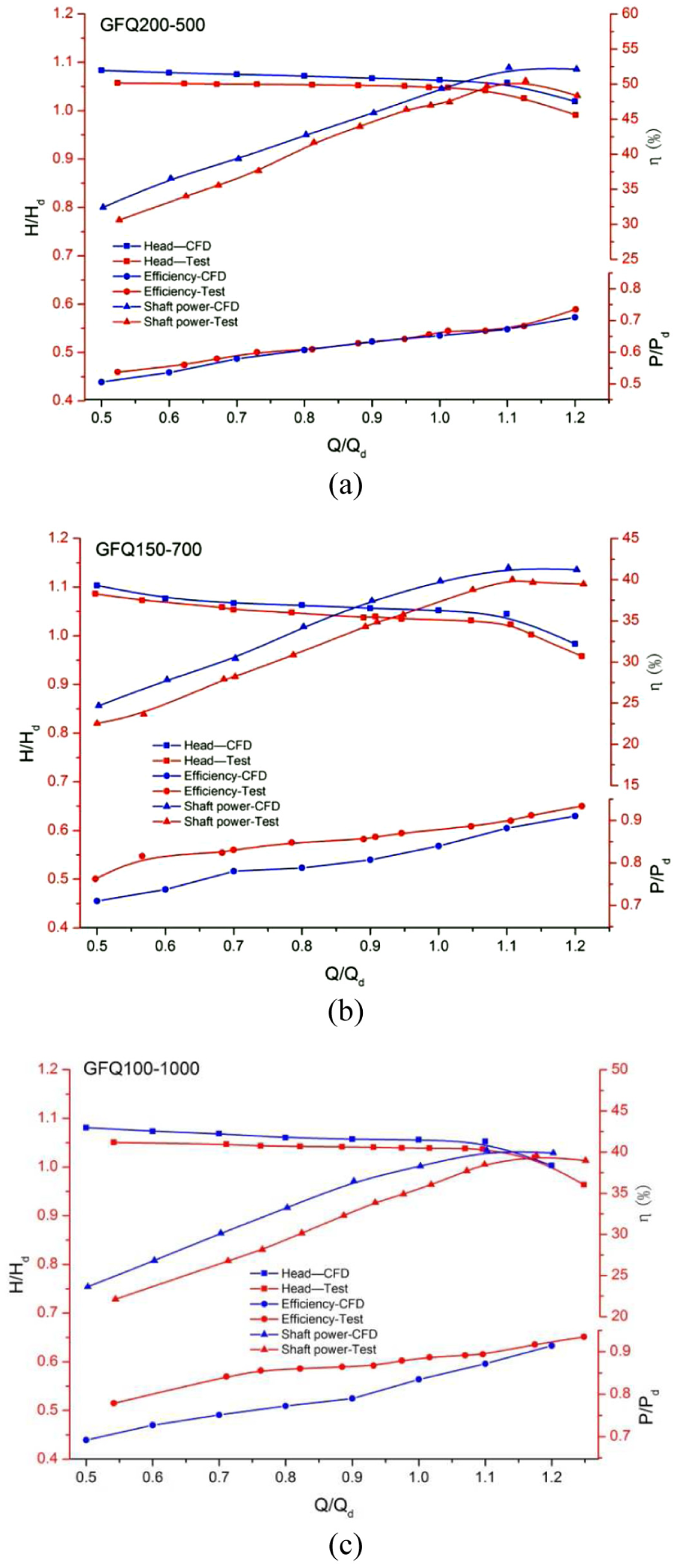
Comparison between experimental data and numerical simulation: (a) GFQ200-500, (b) GFQ150-700, and (c) GFQ100-1000.
Numerical simulation of axial thrust
Types of axial thrust
In the CFD post-processing, the surface pressure and the force of the rotating hydraulic parts such as the induction wheel and the impeller can be extracted directly.
Figure 7 shows the axial thrust of the impeller. N1 and N2 are the axial thrusts on the outside of the front and rear covers. N3 is the axial thrust on the seal end face of impeller. N4 is the axial thrust on the inlet part of the impeller rear plate. The calculation of the cover force includes N3 and N4, namely, F1 = N1 +N2 + N3 + N4, which is consistent with the theoretical formula.

Axial thrust component of impeller.
The numerical simulation method mainly extracts and studies the following axial thrusts on the rotating hydraulic parts:
The axial thrust on front and rear cover outside the impeller cover plate: cover force F1.
The axial thrust on the impeller front and rear cover inner surface (not including the rear cover inlet part): inner channel force F2.
The axial thrust on the impeller blade surface: impeller blade force F3.
The axial thrust on the inducer blade surface: inducer blade force F4.
The sum of these components is the high-speed mine submersible pump hydraulic axial thrust F5, which is the force on the hydraulic parts by the medium in the rotation. The total axial thrust of the unit is equal to the hydraulic axial thrust plus the rotor gravity, namely, F = F5 + T4.
Results and analysis of total axial thrust
The hydraulic axial thrust curve with the flow rate is shown in Figure 8, it can be seen that the hydraulic axial thrust direction is positive, and that is directed to the +x. Hydraulic axial thrust decreases with the increase in the flow rate in the 0.5Q–1.2Q flow rate range, which is due to the low head in the larger flow conditions. The blade work is weak, and the reaction of the working medium to the leaf surface is weak. The hydraulic axial thrusts of GFQ200-500, GFQ150-700, and GFQ100-1000 unit at the 0.5Q condition are 2227.9, 3282.0, and 2881.4 N. These thrusts are at the same order of magnitude as the rotor gravity and the determinants of the magnitude of the total axial thrust in the case of similar gravity of each unit rotor. The hydraulic axial thrust value of GFQ200-500 unit is the smallest of the three pumps, and GFQ150-700 unit is the largest. It is the same as the total axial thrust comparison. The total axial thrust of each high-speed mine submersible pump is 6439.8, 7581.2, and 7249.1 N by hydraulic axial thrust plus rotor gravity. This is consistent with the test situation. The hydraulic axial thrusts of three units from numerical simulation are 1740.8, 2366.7, and 1928.7 N at the designed flow rate condition. Figure 9 shows the hydraulic axial thrust comparison of three high-speed mine submersible pump units between numerical simulation and calculation of the theoretical formula. It can be seen that the GFQ200-500 and GFQ150-700 hydraulic axial thrusts of numerical simulation are slightly larger than the results of theoretical calculation. GFQ100-1000 is significantly smaller. GFQ150-700 hydraulic axial thrust mutation is likely to be the reason of the test phenomenon. It is assumed that the axial thrust component change is related to the impeller series.

Hydraulic axial thrust curve.
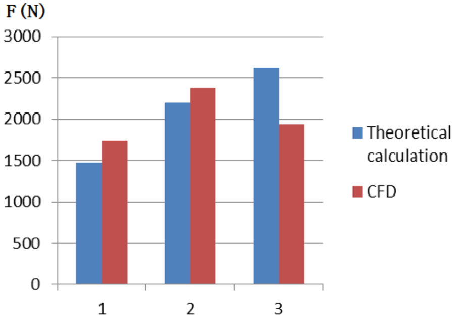
Comparison between theoretical calculation and numerical hydraulic axial thrust results.
Results and analysis of axial thrust components
Each unit’s axial thrust of numerical simulation is consistent with the test case, and GFQ150-700 thrust institution was damaged during the initial test and the other two tests were not. But it does not agree with the theoretical calculation, we need to analyze the magnitude of the axial thrust and change further. Figure 10 shows the F4-Q curve of the axial thrust on the inducer blade surface at different flow rates. As the pressure on the pressure surface of the inducer blade is larger than the suction surface, the direction of the inducer blade force is the same as the force on pressure surface. This force is directed to the +x. The inducer blade force size of the same inducer is related to the work ability of the blade, and the inducer head decreases with the increase in the flow rate. The force is also inversely proportional to the flow rate.

Inducer blade force curve Q/Qd.
The inducer blade force value of GFQ100-1000 unit is the smallest of the three pumps, and GFQ200-500 unit is the largest. The head of GFQ200-500 and GFQ150-700, GFQ100-1000 inducer is also reduced in turn.
The traditional theoretical formula could not accurately calculate the size of the impeller cover force, and it is mainly because the theoretical assumptions are different from the actual situation. Liquid leakage from the chamber on both sides of the cover to the wear ring clearance and the irregular angular velocity of actual rotation result in a deviation in the calculation of the pressure distribution on the front and rear covers. The cover plate force on the impeller cover was obtained by solving the integral value of the static pressure at each point of the cover plate. The cover plate force’s direction is positive, and the direction is directed to the +x. The variation of the cover force with the flow rate curve is shown in Figure 11, and the trend of impellers is basically the same, the cover force decreases with the increase in the flow rate. It is due to the head of impeller decreases with the flow rate increase, and the pressure on the outside of the front and rear covers is also reduced. The cover plate force value of GFQ200-500 unit is the smallest of the three pumps, and GFQ100-1000 unit is the largest. This is consistent with the size of the pump head. The size of GFQ200-500 units cover plate force is close to the first-stage impeller of GFQ100-1000 unit, and it is because the first-stage impeller head of GFQ100-1000 unit is almost identical to the GFQ200-500 unit. The cover plate force of secondary stage impeller is slightly larger. Static pressure distribution in the same radius before and after the cover is not absolutely uniform. The overall pressure of the secondary stage impeller is higher than the first-stage impeller. In this case, the difference of pressure is easily increased, and the cover plate force of secondary stage impeller is slightly larger. But the cover plate force value is less than GFQ150-700 impeller cover force. At the design flow rate condition, the cover plate force of numerical simulation is larger than the theoretical calculation. The difference of GFQ200-500, GFQ150-700, and GFQ100-1000 is 547, 1015, and 1690 N, respectively, in turn. The difference is not large. It can be seen that the wear ring with balance hole on the impeller is very effective to balance the cover plate force.
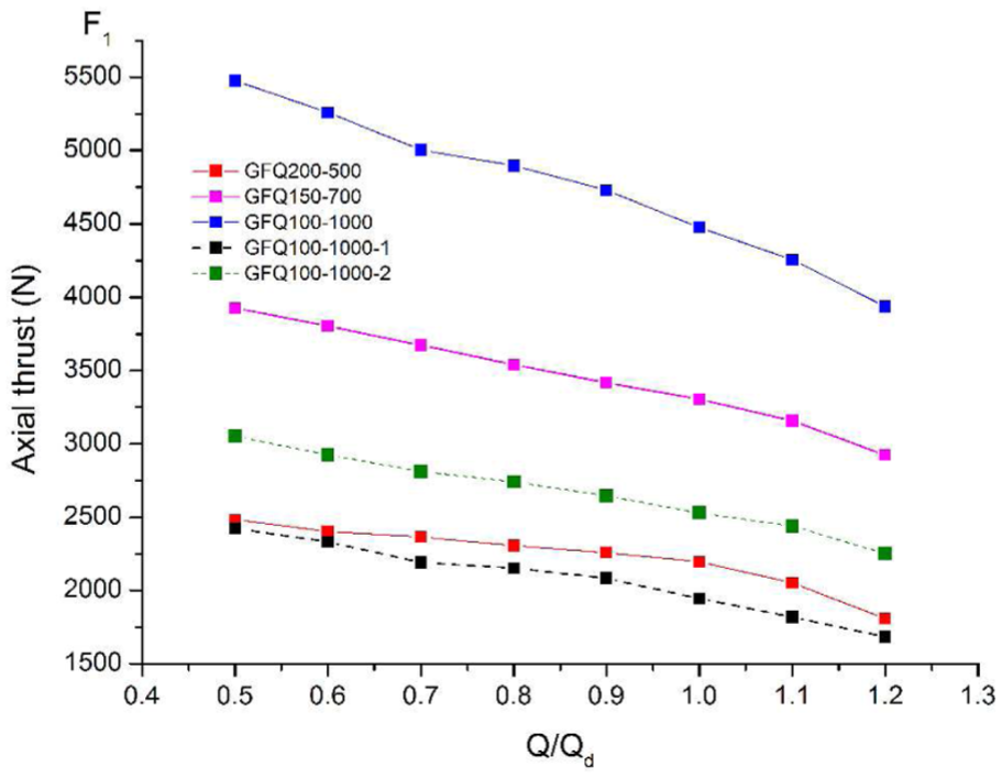
Impeller cover plate force curve Q/Qd.
The inner channel force on the inner surface of the impeller front and rear cover, and the impeller blade force on the twisted blade surface of impeller are extracted and analyzed in numerical simulation. Figure 12 shows the F2-Q curve of the inner channel force on the inner surface of the impeller front and rear cover at different flow rate conditions. It does not include the axial thrust in the inlet part of the rear cover. The inner channel force direction is negative, and the direction is directed to the −x direction. From the flow-path inertial force distribution in the axial projection map, it can be derived that the direction of the inertia force caused by the coriolis force and the channel curvature is consistent with the pressure direction in the inner surface of the rear cover, but the direction is opposite in the inner surface of the front cover. The inner surface pressure on the front cover is partially offset by inertial force. The force on the surface of rear cover is the main inner channel force. The size of the inner channel increases with the increase in the flow rate. When the total pressure of the inflow is constant, the relative velocity increases in the impeller with the flow rate increase leading to the kinetic energy increasing and the pressure reducing. Although the overall average pressure on the inner surface of the front and rear covers is reduced due to the descent of the head, the increase in the inertia force causes the lateral pressure difference to increase. Finally, the inner flow force increases. The inner channel force value of GFQ200-500 unit is the smallest of the three pumps, and GFQ150-700 unit is the largest. The size of GFQ200-500 units inner channel force is close to the first-stage impeller of GFQ100-1000 unit.

Impeller cover internal flow force curve Q/Qd.
The secondary impeller inner channel force of GFQ100-1000 unit is larger than the GFQ150-700 unit, but the head of GFQ150-700 impeller is about 1.4 times of the single impeller of GFQ100-1000. When the impeller head is higher, the rear cover static pressure integral value is larger than the front cover and the inner channel force is larger between the different impellers. But when the impeller series is different, the overall pressure and lateral pressure difference of the secondary impeller of GFQ100-1000 units is higher than the GFQ150-700 single-stage impeller. So, the inner channel force of GFQ100-1000 unit’s secondary impeller is larger than the GFQ150-700 unit.
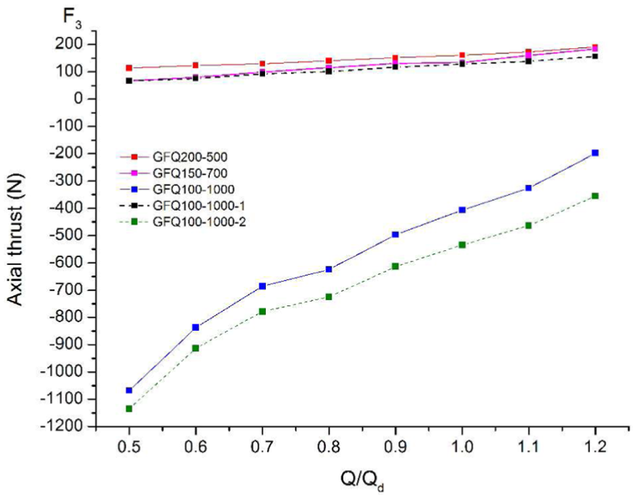
Figure 13 shows the impeller blade force curve, it can be seen that the impeller blade force directions of GFQ200-500, GFQ150-700, and GFQ100-1000 first-stage impeller are positive, and the direction is directed to the +x direction. These impeller blade forces increases with the increase in the flow rate, and the value is in the range of 50–200 N. The impeller blade force direction of GFQ100-1000 secondary stage impeller is negative, and the direction is directed to the −x direction. The absolute value of the impeller blade force decreases rapidly with the increase in the flow rate, its value is between 350 and 1050 N. It dominates that the impeller blade force exists in the GFQ100-1000 unit.
Impeller blade surface force curve Q/Qd.
The impeller blade surface area and the projected area in the vertical direction are extracted in the three-dimensional software. Their data are shown in Table 2, and two impellers of GFQ100-1000 unit have the same structure and data. It can be seen that the pressure surface and the suction surface areas of the three impellers are obviously not equal, and the projected areas in the vertical direction are not equal. The pressure and the pressure area and on both sides of the twisted blade are not equal, and these two are the main generating factors of the impeller blade force. The direction of the lift which the liquid acts on the blade airfoil is directed from the pressure surface to the suction surface at the blade work. Its axial component’s direction is positive. Pressure on the pressure surface is larger than the suction surface, but pressure area of the suction surface is larger than the pressure surface. The direction of the axial thrust generated by the unequal of the pressure area is negative. The pressure difference on both sides of the blade increases with the increase in the flow rate, and the relative velocity increases in the impeller leads to the inlet flow angle increasing and the angle of attack decreasing and the lift axial component increasing. The overall average pressure in the impeller decreases, but the pressure difference increases with flow rate increasing. The axial thrust generated by the unequal of the pressure area is mainly affected by the overall pressure in the impeller. It decreases with flow rate increasing. In the first impeller or single-stage impeller, the pressure difference on both sides of blade is larger, and the impeller blade force direction is positive. When the flow rate increases, the decrease in the axial thrust generated by the unequal of the pressure area is faster than the pressure difference, which increases the blade force. The overall pressure in the GPQ100-1000 unit secondary impeller is very large, and the axial thrust generated by the unequal of the pressure area is larger than the pressure difference. The direction of the impeller blade force changes to negative, and the absolute value of the impeller blade force decreases with the increase in the flow rate.
The impeller blade surface area and the projected area.

PSA: pressure surface area; PSPA: pressure surface projected area in the vertical direction; SSA: suction surface area; SSPA: suction surface projected area in the vertical direction.
Discussion
It can be seen from the comparison of the results between numerical simulation and theoretical calculation that the predicted high-speed mine submersible pump axial thrusts are approached by two methods with small error. The predicted axial thrust is less than 1.1 × 10⁴ N, which is the original thrust institution can withstand. But the initial test situation of the GFQ150-700 unit indicates that its axial thrust has exceeded the ultimate limit of the original thrust institution. It is speculated that the current calculation method of the thrust institution design method has a big error with the actual high-speed situation. It cannot accurately design a safe and reliable thrust institution.
The cover force F1 is the most important axial thrust component, and the inner channel force F2 is also an important force to affect the hydraulic axial thrust, and the inducer blade force F4 is small. In the first impeller or single-stage impeller, the impeller blade force F3 is also smaller than the cover force and the inner channel force. But in the multi-stage impeller, the overall pressure in the impeller is larger, and the axial thrust generated by the unequal of the pressure area in the twisted blade is larger than the pressure difference. Besides, the direction of the impeller blade force F3 is changed. At this time, the impeller blade force counteracts the partial axial force of the positive direction, and the total axial thrust of GFQ100-1000 unit is reduced, smaller than the GFQ150-700 unit. This can explain the situation that only GFQ150-700 unit was damaged in the test, and GFQ100-1000 unit was tested successfully even if its axial thrust of theoretical calculation is larger.
Conclusion
This article has investigated the axial thrust deviation between the theory and experiment for high-speed mine submersible pump. The test results of axial thrust are not consistent with the theoretical results. The influence of each axial thrust component on the overall axial thrust is analyzed and discussed. In this article, some conclusions are given as follows:
The theoretical assumptions of the pressure distribution on the rotor parts are different from the actual, and the complex inner channel force F2 and impeller blade force F3 in the impeller. The traditional theoretical formula cannot accurately calculate the value of the high-speed mine submersible pump axial thrust.
The initial test situation of the GFQ150-700 unit indicates that its axial thrust exceeds the ultimate limit of the original thrust institution. It is speculated that the current calculation method of the thrust institution design method has a big error with the actual high-speed situation. It cannot accurately design a safe and reliable thrust institution.
The axial component of impeller blade force simulated in the impeller plays an important role in axial thrust calculation and deviation. In the single-stage impeller structure, hydraulic axial thrust components are mainly affected by the internal pressure of the impeller. The impeller blade force is generated by the pressure difference on both sides of the twisted blade, but also produced from the unequal projected area of blade surface in the vertical direction on both sides. The direction of the impeller blade force in the single-stage impeller structure depends mainly on the uneven pressure distribution on both sides of the blade, but the decrease in the axial thrust generated by the unequal of the pressure area is faster than the pressure difference. The impeller blade force increases with flow rate increase. But in the case of multi-stage impeller, the direction and value of the impeller blade force depend mainly on the unequal of the pressure area on both sides of the blade. The impeller blade force decreases with the increase in the flow rate at this case. The axial thrust generated by the unequal of the pressure area is increased rapidly due to the overall pressure increase, and it changes the direction of the impeller blade force. It becomes an important factor in predicting the value and direction of the total axial thrust.
Finally, we hope that the research could serve in further improve the reliability of the high-speed mine submersible pump design.
Supplemental Material
Supplementary_File_(1) – Supplemental material for Investigation of axial thrust deviation between the theory and experiment for high-speed mine submersible pump
Supplemental material, Supplementary_File_(1) for Investigation of axial thrust deviation between the theory and experiment for high-speed mine submersible pump by Bin Xia, Fanyu Kong, Hui Zhang, Lei Yang and Wanghuan Qian in Advances in Mechanical Engineering
Footnotes
Appendix 1
Handling Editor: Takahiro Tsukahara
Declaration of conflicting interests
The author(s) declared no potential conflicts of interest with respect to the research, authorship, and/or publication of this article.
Funding
The author(s) received no financial support for the research, authorship, and/or publication of this article: This work was supported by National Natural Science Foundation of China (No. 51505192), the Top-notch Academic Programs Project of Jiangsu Higher Education Institutions (PPZY2015A086), and the Project supported by Science and Technology Innovation Team of Jiangsu Provincial University in China (No. 2015-4).
Supplemental material
Supplemental material for this article is available online.
References
Supplementary Material
Please find the following supplemental material available below.
For Open Access articles published under a Creative Commons License, all supplemental material carries the same license as the article it is associated with.
For non-Open Access articles published, all supplemental material carries a non-exclusive license, and permission requests for re-use of supplemental material or any part of supplemental material shall be sent directly to the copyright owner as specified in the copyright notice associated with the article.