
Abstract
High-speed trains have a sustained high-noise level for long periods during operation. Although such high-noise levels are effective for acoustic energy harvesting, a practical design for an acoustic energy harvesting system from a high-speed train is lacking. In this study, the design of an energy harvesting system was implemented utilizing noise from a high-speed train during practical operation. We investigated the noise generated from a high-speed train and derived the characteristics of the main noise sources. The results confirmed that low-frequency noise of 50–200 Hz was generated in the passenger, cab, and between car sections. Results from this investigation were used to design a Helmholtz resonator for a target noise of 174 Hz based on a theoretical model. Moreover, numerical simulation was conducted using sound source speakers to investigate vibrations in the walls of the resonator. Finally, energy harvesting experiments were conducted using various types of piezoelectric elements such as rectangular and circular plates. Experimental results indicate that approximately 0.7 V was generated for an incident sound pressure level of 100 dB using a large rectangular plate. Such power level is sufficient to power a variety of low-power electric devices.
Keywords
Introduction
Recently, research on energy harvesting technology has been actively carried out due to the development of sensor technology with low power consumption.1,2 Energy harvesting refers to the technology of harnessing external energy such as solar energy and human body kinetic energy and recycling it as electric energy. Because energy harvesting can harness electrical energy directly from natural sources, it has attracted increased interest as an eco-friendly energy utilization technology that can maintain energy supply stability, security, and sustainability, as well as reduce environmental pollution.
Among the various energy sources, the technique of harvesting energy from sound generated from the surroundings has the possibility of being widely utilized. However, acoustic energy harvesting technology has practical limitations because of its low energy density compared to other sources.3,4 To overcome this limitation, an energy-conscious system design and implementation methodology have been proposed to obtain improved efficiency compared to existing technologies. 5
In recent years, techniques for generating electricity from vibrations in a light structure using sound from the surroundings have been studied. A circular and piezoelectrically active diaphragm for acoustical-to-mechanical and mechanical-to-electrical conversion has been proposed. 6 In this research, a maximum output power density of 0.34 μW/cm2 was obtained at 149 dB. 6 In Liu et al., 7 it was shown that the efficiency of an acoustic energy harvesting system can be increased by an electromechanical Helmholtz resonator (EMHR). The EMHR consists of an orifice, cavity, and piezoelectric diaphragm. Experimental results indicate that approximately 30 mW of output power was harvested for an incident sound pressure level of 160 dB using a flyback converter. 7
In addition, acoustic energy harvesting using curved piezoelectric beams in the cavity of a sonic crystal was investigated.8,9 In this research, a resonant cavity of the sonic crystal was used to localize the acoustic wave as the acoustic waves were incident on the sonic crystal at the resonant frequency. Then, energy harvesting was implemented when the acoustic waves are incident at the resonant frequency. Moreover, two types of electromagnetic power generators were used by employing the direct conversion of airflow into mechanical vibration. 10 In this research, the Helmholtz-resonator-based energy scavenger achieved a peak-to-peak output voltage of 4 mV from an input pressure of 0.2 kPa, which is equivalent to a wind velocity of 5 m/s. An airflow energy harvester has also been implemented by combining a piezoelectric energy harvester with a Helmholtz resonator. 11 The resonator converts airflow energy to air oscillations, which are then converted into electrical energy using the piezoelectric harvester; the maximum power obtained was 42.2 µW at 20 m/s. 12 To achieve efficient acoustic energy harvesting, a Helmholtz resonator with single-layer and multilayer piezoelectric composite cantilevers was used. 13 Results of the feasibility study of this research show that a maximum power of 0.19 μW can be achieved with sound waves of 118 dB at 850 Hz. In addition, an efficient acoustic energy harvester was proposed that is suitable for low-frequency bands. 14 It is composed of a tunable Helmholtz resonator with a flexible bottom, with affixed piezo disk and proof mass. In this research, experimental results show that the proposed harvester can generate 3.49 μW when both resonance frequencies are matched, and the energy conversion efficiency can reach up to 38.4%.
In this study, a new method is proposed to harvest energy from traffic noise that is commonly encountered in everyday life. Specifically, noise generated from a high-speed train is higher than in other modes of transportation except for noise from airplanes. However, there are few available studies on energy harvesting from noise generated by a high-speed train. To harvest energy from such energy source, it is necessary to determine the characteristics of noise generated in the high-speed train. In this study, we investigated the characteristics of noise generated at various positions in high-speed train and used the results to determine the characteristics of the main noise sources. Then, a Helmholtz resonator was designed based on the characteristics of the main noise sources. A variety of piezoelectric elements were used to obtain high electric energy by the vibration of the Helmholtz resonator. Experimental results indicate that approximately 0.7 V was generated for an incident sound pressure level of 100 dB using a large rectangular plate. The proposed acoustic energy harvesting method is validated using noise that occurs in the same frequency range as during the operation of a high-speed train. The results from this study indicate that sufficient electricity can be harvested from noise generated from a high-speed train.
Noise characteristics analysis
In this section, details of a study conducted to determine the characteristics of noise generated by a traveling high-speed train are presented. Noise sensors were installed at various locations in the high-speed train to measure the noise generated during operation. The noise sensors (BSWA, 1/2″) were installed in the cab, passenger, and between car sections in order to measure noise in the interior of a next generation high-speed train, as shown in Figure 1. Indoor sensors were performed by measuring the location of the height of 1.2 m from the bottom. In addition, propagation noise from the high-speed train was measured using a sensor (BSWA, 1/2″) at a height of 1.2 m from the rail head and at a distance of 8 m from the center of the rail. The measurement positions of interior and exterior noise were selected by referring the international standards of EN ISO 3381-Railway applications-Acoustics. Measurements and analysis were carried out using PXI devices (DAQ board: PXIe-1065; controller: PXIe-8133; data streaming: NI 8260) from National Instruments. Data from the high-speed train traveling at a speed of 300 km/h were measured at the Song-Ra region on the Gyeongbu high-speed line.
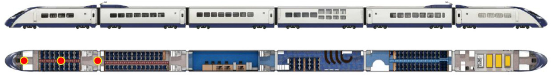
Noise measurement location in a next generation high-speed train.
The measured noise level in the passenger room was in the range of 66–70 dB at a speed of 300 km/h, and the main frequency range was 80–200 Hz. The noise level of the high-speed train was approximately 66 dB when traveling on a straight line on a gravel track, while the noise level increased by 3–5 dB in a tunnel or bridge. The measured noise level in the cab was 70–80 dB and the main frequency range was 50–200 Hz, as shown in Figure 2. Noise in the interior between car sections was in the range of 90–110 dB when traveling between open and tunnel environments. The increase in noise occurred in the frequency range of 80–200 Hz, as shown in Figure 3. In addition, the measured external noise in the high-speed train was over 95 dB, as shown in Figure 4. Additional measurement and contribution analysis are required to analyze low-frequency noise. Especially, in the railway, the operational transfer path analysis was used to analyze the characteristics of interior noise. 15 However, this study did not carry out the contribution analysis because the measurement aimed to obtain the main characteristics of the measured signal. External noise was measured at a distance of 8 m from the center of the track and 1.2 m above the top of the rail. The result confirmed that noise in the low-frequency range below 200 Hz was measured in various locations of the high-speed train. In particular, the measured noise between car sections confirmed that high noise continuously occurred in the low-frequency region.
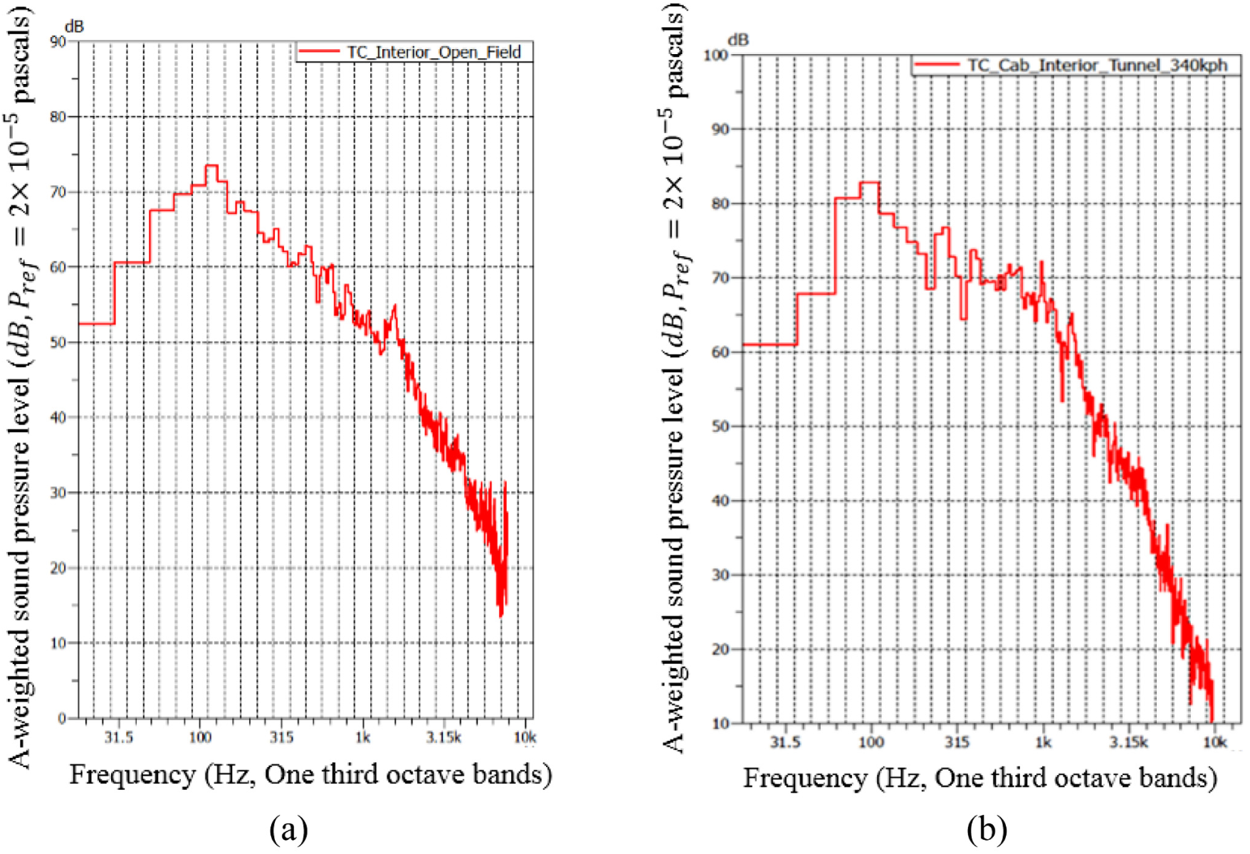
Interior noise of passenger and cab room at speed of 300 km/h: (a) open field and (b) tunnel.

Interior noise between car sections while traveling in open and tunnel environments: (a) open field and (b) tunnel.

External noise of high-speed train at speed of 300 km/h.
Therefore, to harvest energy from the high-speed train, it is necessary to carry out a design based on noise in the low-frequency region.
Helmholtz resonator design
The Helmholtz resonator is an acoustic device consisting of a cavity and a narrow neck with a relatively large volume compared to the volume of the neck. If the dimensions of the design parameters are sufficiently small compared to the wavelength of the sound wave of interest, the fluid particles located in the narrow neck of the resonator will experience a uniform motion over the neck cross section.16,17 In this case, a Helmholtz resonator can be represented as a 1 degree-of-freedom mechanical system, as shown in Figure 5.

Helmholtz resonator structure and mass–spring model.
Assuming that the physical phenomena that occur in the Helmholtz resonator are represented by continuity equations and momentum equations, and that there is no energy loss, the impedance of the Helmholtz resonator can be expressed as

where
The resonance of the resonator occurs when the impedance is minimum, and the resonance frequency of the resonator is given by

In this section, details of the design of a Helmholtz resonator based on the noise characteristics of a high-speed train are presented. It can be observed from the noise measurement of the high-speed train that a high amount of noise was generated in the frequency range of 50–200 Hz. Therefore, in this study, the target frequency domain was selected as 174 Hz. The overall size of the Helmholtz resonator was determined using the size of the cavity. 18 Furthermore, the size of the cavity should be appropriately determined in order to be applied to a specific location in the high-speed train car. Especially, there is sufficient space for installing a cube with a side length of 0.1 m at the between-cars section of high-speed trains. In this study, the size of the cavity was set as a cube with a side length of 0.1 m. In the condition of the cavity, the length of the neck was designed to be 0.02 m based on the target frequency of 174 Hz as shown in Figure 6.

Target frequency range according to neck length.
Based on the designed Helmholtz model, numerical analysis was carried out to investigate the vibrations from the incident sound. First, the Helmholtz model was built for numerical analysis, as shown in Figure 7. For the implementation of this model, 13,183 elements were constructed using 18,217 node points. The material used for this model was acrylic with a density of 1129 kg/m3, Young’s modulus of 1.79 GPa, and Poisson’s ratio of 0.37. The density of the air layer medium was 1.2 kg/m3 and the speed of sound was set as 343 m/s. A monopole was used a source for sound pressure and was located 0.1 m from the center of the entrance of the neck. In this case, the magnitude of the sound pressure was 100 dB and the radius of the pulsating sphere was 0.01 m. ANSYS simulation software was used in this research for numerical analysis. The frequency of the resonator was analyzed through numerical analysis. Therefore, this simulation analysis was focused on visualizing the distribution of the sound field when noise was propagated at the target frequency.

Helmholtz model for numerical analysis.
From the results of the analysis, it was confirmed that a high sound pressure was generated inside the cavity in the region of 174 Hz, as shown in Figure 8. It can be observed that resonance occurred due to high sound pressure generated inside the resonator. Based on the results of the analysis, it was confirmed that a maximum sound pressure of 120 dB was generated inside the cavity. The acoustic velocity vector results show that high fluctuation occurred at the neck part in the Helmholtz resonator, as shown in Figure 9. Furthermore, it was confirmed that the wall of the cavity vibrates due to resonance.

Sound pressure level of Helmholtz resonator at frequency of 174 Hz.

Acoustic velocity vector of Helmholtz resonator at frequency of 174 Hz.
After the analytical examination, experiments were conducted to analyze the Helmholtz resonator. In the experiment, the vibrations occurring in each wall of the cavity were measured using the acoustical excitation of a loudspeaker in the Helmholtz resonator. The LMS SCADAS Mobile (Siemens) was used for this measurement. We also used accelerometers (PCB Piezotronics) to measure the vibration, while a sound speaker (Britz) was used for generating noise, as shown in Figure 10. The speaker was installed at a distance of 0.1 m from the entrance of the neck in the resonator. In this experiment, the speaker was set to generate 100 dB of white noise. In the external car-body in between-cars section of high-speed train, high noise of more than 100 dB occurs due to the inflow of the flow. 19 The magnitude of the vibration generated from the top, back, and side of the Helmholtz resonator was measured using the accelerometers.

Measurement equipment of Helmholtz resonator.
The magnitude of vibration occurring in various walls of the Helmholtz resonator was measured using the speaker acoustic exciter, as shown in Figure 11. Based on the vibration occurring on each surface in the frequency domain, it can be observed that the highest vibration occurred in the 174 Hz of the frequency region due to resonance. The highest vibration occurred at the back surface of the resonator, and a maximum value of 4.93 m/s2 was measured in this section. The maximum measured value at the top surface of the resonator was 4.11 m/s2. The least vibration occurred at the side surface, and the maximum measured value in this section was 1.20 m/s2. These measurements indicate that high vibrations occur at the back and top surfaces of the resonator due to acoustic excitation.

Vibration of various surfaces in Helmholtz resonator.
Energy harvesting with piezoelectric
In this section, details of experiments conducted to harvest electric energy using Helmholtz resonator through the acoustic exciter are presented. From the results of the vibration measurement of the resonator, it was confirmed that the resonance of the sound generated high vibration on the wall surface. Therefore, in this study, we propose a method for attaching piezoelectric elements directly to the resonator wall surface to obtain high electrical energy.
To investigate the efficiency of the electric energy generated by the Helmholtz resonator, experiments were conducted using various types of piezoelectric elements, as shown in Figure 12. The area of the piezoelectric element of the rectangular flat plate was 3.5 × 10⁻³ m2, and the areas of the large and small circular plates were 0.527 and 0.314 m2, respectively. The area of the thin film type cantilever beam was 0.130 m2. A variety of piezoelectric elements were used to effectively harvest energy from the resonator.

Various types of piezoelectric units.
In this experiment, the electric energy generated in the piezoelectric element was measured using the acoustic excitation of the speaker attached to the resonator. The speaker was set to generate 100 dB of white noise and was located 0.1 m from the resonator entrance. The mean value of the voltage generated for 10 s was used in the measurement.
From the results of the voltage measurement for the rectangular plate of the piezoelectric unit, it was confirmed that voltages of 0.22–0.70 V were generated for each mounting position of the surface as shown in Figure 13. In particular, it was confirmed that a peak voltage of 0.7 V was generated at the back surface. This voltage is sufficient to power various electronic components.

Voltage generation from rectangular plate of piezoelectric unit.
From the results of the voltage measurement for the large circular plate of the piezoelectric unit, it was confirmed that voltages of 0.11–0.43 V were generated for each mounting position of the surface as shown in Figure 13. On the other hand, from the results of the voltage measurement for the small circular plate of the piezoelectric unit, it was confirmed that voltages of 0.11–0.37 V were generated for each mounting position of the surface. A comparison of the two results shows that the higher the area of the piezoelectric element, the higher the generated voltage.
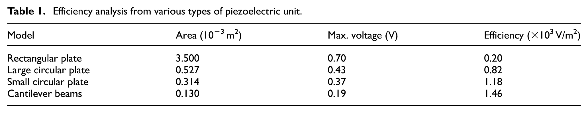
Results of the voltage measurements for the cantilever beams of the piezoelectric unit confirmed that voltages of 0.19–0.07 V were generated for each mounting position of the surface as shown in Figure 13. In the cantilever beam, the smallest voltage was generated because of the small area. However, the voltage generated by the cantilever beam is sufficient to power conventional MEMS sensors. However, an analysis of the efficiency of generating the maximum voltage based on area confirmed that the cantilever beam shape had the highest efficiency of 1.46 × 10³ V/m2 as presented in Table 1. Therefore, in the case of a single piezoelectric unit, the higher the area the higher the voltage, and the smaller the area the higher the efficiency.
Efficiency analysis from various types of piezoelectric unit.
Conclusion
In this study, the design of an energy harvesting system based on noise from a high-speed train during practical operation was implemented. First, we investigated the noise generated from the high-speed train and derived the characteristics of the main noise sources. The results confirmed that low-frequency noise of 50–200 Hz was generated in the passenger, cab, and between car sections. Results from the investigation of the noise characteristics were used to design a Helmholtz resonator for a target noise of 174 Hz based on a theoretical model. Moreover, numerical simulation was conducted using sound source speakers to investigate the vibration of the walls of the resonator. Finally, energy harvesting experiments were conducted using various types of piezoelectric elements such as rectangular and circular plates. Experimental results indicate that approximately 0.7 V was generated for an incident sound pressure level of 100 dB using a large rectangular plate.
Footnotes
Handling Editor: Yong Chen
Declaration of conflicting interests
The author(s) declared no potential conflicts of interest with respect to the research, authorship, and/or publication of this article.
Funding
The author(s) disclosed receipt of the following financial support for the research, authorship, and/or publication of this article: This research was supported by a grant from R&D Program of the Korea Railroad Research Institute, Republic of Korea.