
Abstract
Fully mechanized roadway is an area of high accident incidence, and the problem is more prominent with the increase of mining depth of coal resources. The advance support scheme put forward for fully mechanized mining roadway with self-moving support and anchor combined unit, and the configuration and working principle of support robot was explicated. A determination method on the working resistance of advance support bracket was proposed based on mechanical coupling model of surrounding rock-advance support brackets. Taking the geological conditions of the Qishan mine as an example, the process of analyzing and determining the working resistance of the advance support bracket was described using this method. An advance support bracket was designed using SolidWorks, and the working load was obtained based on numerical calculations. Then the stress and strain were analyzed using ANSYS. The results showed that the designed advance support bracket can withstand the corresponding top plate pressure. It provides a new method and thought for study and development of advance supporting equipment in deep fully mechanized roadway.
Keywords
Introduction
Fully mechanized driving face is an accident-prone area, workers always bear a serious security threat.1–3 With the increasing depth of coal resources mining, more and more mines will face severe deep mining problems,4,5 high geostress, severe strata pressure, enlargement of plastic zone and crush zone of surrounding rock,6–8 obvious increase in displacement of two-side walls of roadway, and bulge of bottom of roadway.9–11 During the excavating process, excavation time is much longer than the support time, and the imbalance of used time between excavation and support is prominent. Therefore, it is one of the key problems to be solved for fully mechanized excavation face, especially in deep coal mine, to explore study safe and efficient advance support scheme and to design new support equipment, which could provide security guarantee and improve the supporting efficiency.12–14 At present, many scholars and manufacturers at home and abroad carried out a lot of investigations on the advance supporting for fully mechanized driving face. Shandong Heibao Company, Ltd designed and manufactured a stepping-forward support bracket. Xie et al. designed a kind of stepping-forward support equipment, developed experimental prototype, and carried out the experimental study on roof-advance support coupling mechanics.15,16 But the above research mainly focused on the structure performance of the designed advance support, and the overall design laid particular emphasis on empirical design and with less consideration of the organic combination of the advance support design method and the surrounding rock support theory.17–20
In this article, the advance support scheme for fully mechanized roadway put forward and the working principle of supporting robot which is the key equipment in the support scheme is introduced first. Then the variation law of surrounding rock pressure in deep coal seam and its impact mechanism on the advance support bracket were studied through the mechanical coupling model of surrounding rock and advance support bracket, and the related mechanical parameters and mechanical load of the advance supporting bracket were acquired by numerical simulation with the reference of the geological condition of Qishan Coal mine. Last, a new type of advance support was designed on the basis of above parameters and its stress and strain were discussed under the above mechanical load.
Advance support scheme
Self-moving support and anchor combined unit
Self-moving support and anchor combined unit, which is composed of self-moving advance support bracket, anchor truck, multi-position anchor drill mechanical arm, and other subsidiary devices, can be divided into three parts: tunnel robot, support robot, and anchor robot. The unit has the characteristics of multi-station collaborative operation, harmony of supporting and anchoring, stent stepping forward easily and quickly, drilling anchor mechanism flexible self-moving, and so on. The overall structure of the unit is shown in Figure 1:
The tunnel robot is roadheader with automotive and intelligent function to meet the needs of automation and intelligent remote control. Its main function is to excavate the desirable roadway automatically and intelligently.
The support robot consists of a vehicle for support bracket transport and a series of self-moving advance support bracket with the features of adjustability in height and width to satisfy the need of different roadway cross-section size and bracket forward movement. Its main function is temporary supporting of roadway.
Anchor robot is composed of anchor drilling, two multi-station mechanical arms with the features of multi-station and multi-angle positioning, and other subsidiaries. Its main function is to complete the installation of the bolt at different positions and angles in the roadway to achieve the permanent support of the roadway.
The subsidiaries mainly refer to the platform to hold and carry the hydraulic station and to provide an operation stand for the bracket transport truck and anchor robot.
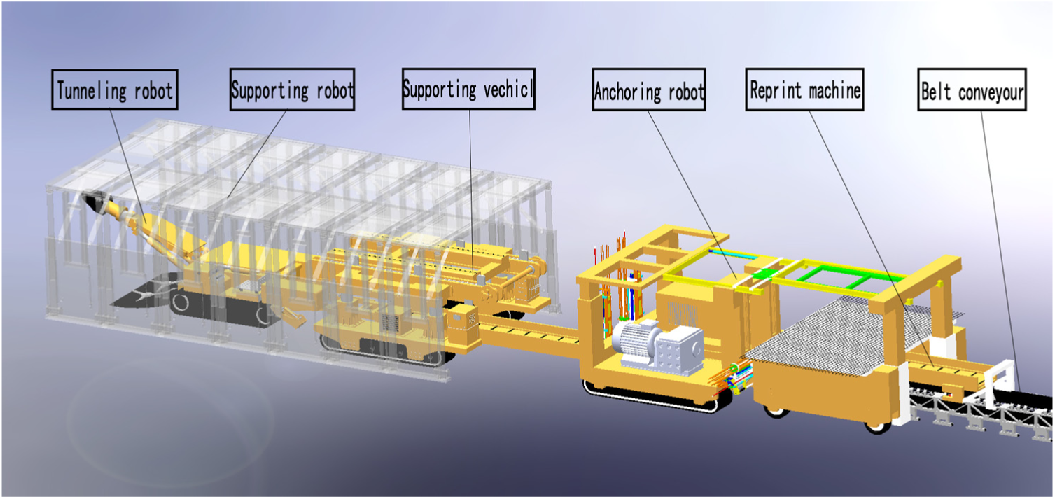
The overall structure of the self-moving support and anchor combined unit.
Support robot
Support robot is composed of several groups of self-moving advance support bracket and transport truck, as shown in Figure 2.

Schematic diagram of the support robot.
The working principle and procedure of the support robot are as follows:
The initial state of the support robot is that all advance support brackets are in the support state with the appropriate height and width to sustain the surrounding strata pressure of the roadway and that the transport vehicle is staying at the end of the support robot to prepare for moving the bracket to the front of the roadway.
After the tunnel robot (roadheader) excavates the roadway forward with the width of one support bracket, the rear support bracket of the support robot contracts to the minimum size, lands, and is clamped on the bracket transport vehicle.
The bracket transport vehicle will carry the advance support bracket from the rear of support robot to the front and release it at the suitable cross-sectional position of the roadway; meanwhile, the anchor robot starts to perform the operations of permanent support for the roadway in back of the support robot.
The advance support bracket stretches and lifts to suitable dimensions in height and width of the near cross-section of the roadway to perform temporary support for the roadway, and simultaneously the bracket transport vehicle goes back to the rear of the support robot for the next transportation and the anchor robot performs the installation operation of bolt at the desirable position continuously.
Then the tunnel robot (roadheader) moves forward to the front of roadway and commence the next procedure of excavation, while the anchor robot accomplishes the permanent support of roadway behind support robot.
Repeat steps (2)–(5) until completion of the excavation of the whole roadway.
With respect to the above procedures, the work flow of every advance support bracket can be summarized as “Pressure Relief–Dropping support pillar–Frame contraction (transverse)–Moved forward–Frame stretching–Lifting support pillar–Pressure stabilization.” Permanent support of the roadway is completed by the anchor robot behind the support robot far from the tunneling face. Thus, on one hand, it keeps the coal workers away from dangerous areas of the roadway sections and protects them against the disasters and health harms; on the other hand, it improves the excavation efficiency of roadway because the anchor robot can run simultaneously and harmoniously with the tunnel robot, which eases the difference in contradiction between excavating time and supporting time at some degree.
Advance support bracket
Structure design
Advance support bracket is composed of telescopic top beam, fender panels, support columns, and pedestal, as shown in Figure 3.

The schematic of the advance support bracket: (a) front schematic drawing and (b) cabinet drawing.
The telescopic top beam includes two parts. One part is main frame with inner wedge groove; the other part is a plate with wedge end to match with the main frame. The two parts are connected with each other by hydraulic cylinder to enable the plate to be retractable and the wedge shape can keep the upper surface being level. Fender panels are connected with the top beam by hydraulic cylinder to safeguard the rib of roadway and the slanting support force to the top beam. Support columns have hinged connection with the telescopic top beam by hydraulic cylinder to realize the function of lifting and stand on the pedestal. Pedestal provides a platform for the other parts of advance support bracket.
Mechanical model
In order to establish the ideal mechanical model, the main assumption is as follows:
Roadway roof, floor, and two groups of forces are of uniform load;
Guard jack and auxiliary roof beam are connected by hinges;
Auxiliary roof beams and support columns are connected by hinges;
Base and the floor for surface contact.
The mechanical model of the bracket is shown in Figure 4, where (1) H is the height of the bracket, (2) L is the width of the bracket, (3) F1 is the pressure of the bracket from the top plate, (4) F2 is the pressure of the bracket from the bottom plate, (5) F4 is for the help cylinder pressure, (6) F5 is to support the column by the pressure, and (7) mg is for the stent weight.
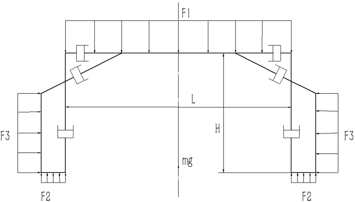
Stent mechanical model diagram.
From Figure 4, we can see the force of the advance support bracket in the vertical direction

Equation (2) provides the force of the top beam in the vertical direction

The strength coupling between the advance support bracket and the surrounding rock is the basis for the stability of the bracket-surrounding rock system. The force of the leading bracket on the top of the bracket and the load of the overlying rock on the top of the bracket are a pair of interaction forces. In the formula, F1 is the pressure of the roof of the roadway to the bracket and can be expressed as follows

where q (x, y) is the distribution function of the overburden on the top of the support (N/m2).
At the same time, the help board and shield section contact with the jack, and retractable roof beam and shield contact with the jack part of the entire stent are the weakest links.
Determination method of working resistance of the advance support bracket
Working resistance
The advance support bracket is one of the key equipments in fully mechanized excavation face. Work resistance is one of the main performance parameters of advance support bracket and also is the design basis of advance support bracket. The magnitude of the working resistance directly determines how much strata pressure can bear, so it has an important significance to safety of production and operation and safety performance of excavation face. Referring to the design and calculation of hydraulic support in fully mechanized mining face, the work resistance of advance support bracket could be achieved by the following formula

Here,
Supporting intensity is one of important parameters affecting the work resistance of the support bracket. If it is too small, the support force of bracket to the roof of the roadway is insufficient, which would easily lead to the safety accidents of roof fall, roof leakage. On the other contrary, if it is too large, the safety performance of the excavation face could be ensured, but the size and the cost of the support equipment would increase and the size of the support equipment would also increase to diminish the operation space for the coal workers. At present, when designing hydraulic support bracket, the determination of the supporting intensity roughly has the following methods, namely, look-up table method, empirical formula method, theoretical calculation method, analogy method, and numerical simulation method. The above methods have some limitations. The study on the advance support bracket for temporary support in roadway also lays particular emphasis on the structure performance design. Furthermore, the structure design of the advance support mainly relies on empirical design and lacks organic combination with roadway surrounding rock support theory.
This article puts forward a new determination method of support strength of advance support bracket based on mechanical coupling model of surrounding rock-advance support bracket.
Flowchart of determination of support strength of advance bracket
The flowchart of determination of support strength of advance bracket is illustrated in Figure 5:
Build the mechanical coupling model of the surrounding rock-advance support bracket based on the proposed structure of advance bracket and the geological conditions of a coal mine where the advance bracket will be used for;
Numerically simulate the deformation of the roadway surrounding rock and the force using the model in Flac3D software;
Get the preliminary support strength of advance bracket with comprehensive consideration of the surrounding rock deformation and the bracket force;
Adjust and determinate the final work resistance of advance bracket by contrast with the result of theoretical estimation.

The flowchart to solve the work resistance.
Calculation example
Taking the geological conditions of Qishan Mine as an example, this article elaborates the process of analyzing and determining the working resistance of advance supporting brackets using the mechanical coupling model of surrounding rock-advance support bracket.
Mechanical coupling model
The occurrence of coal seams and the physical and mechanical parameters of the every seam in Qishan Mine are shown in Table 1. Based on the Mohr–Coulomb yield criterion, the geological model of coalfield is built with length 36 m × width 25 m × height 46.6 m. The trans-section of the roadway model is rectangular with width 5.0 m × height 3.6 m, and divided into mesh girds of 264,584 in total.
Occurrence of coal seams and the physical and mechanical parameters of the every seam in Qishan Mine.

According to the measured results, the load applied at the top of the roadway is calculated at a depth of 1 030 m. A vertical crustal stress of 27.1 MPa and a horizontal crustal stress of 40.5 MPa are applied to the boundary of the roadway.21,22
The initial displacement and velocity of the model are calculated by zero, and the direction of the original principal stress is consistent with the three coordinate axes of the model. In order to analyze the supporting effect of roadway surrounding rock after excavation, it can be simulated according to the self-weight of each rock. The four sides of the model are displacement boundaries, and the horizontal displacement is fixed. The bottom is the displacement boundary, and the vertical displacement is fixed.
Support robot consists of seven groups of advance support brackets, each bracket has length 5 m × width 1.6 m × height 3.6 m, and the material is Q235 steel, and the Flac3D model of the support robot is shown in Figure 6. Figure 7 illustrates the mechanical coupling model of surrounding rock-advance support bracket established according to the above conditions.

Flac3D model of the support unit.
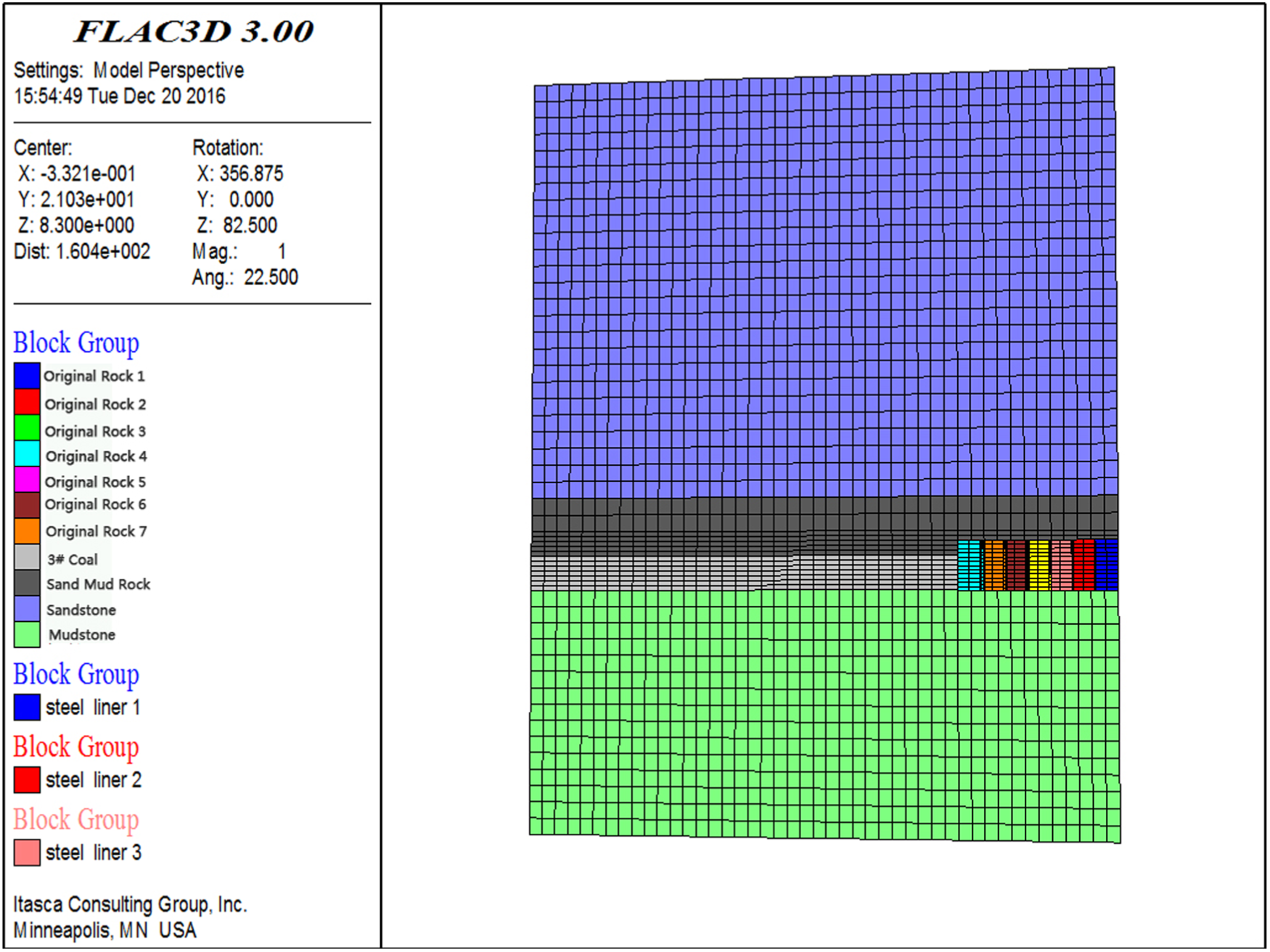
Mechanical coupling model of roadway surrounding rock-advance support bracket.
The relationship between roof subsidence and roof pressure
Through observing the monitoring points set on the top of the roadway, the variation law on the roof pressure with the roadway roof subsidence is obtained by numerical simulation under unsupported condition, as shown in Figure 8.
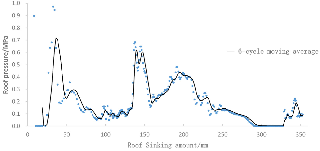
Variation law on the roof pressure with roadway roof subsidence.
As can be seen from Figure 6, with the sinking of the roof, the roof pressure of the roadway is gradually reduced and presents a fluctuating state, in the case where the roadway has no support. When the roadway roof subsidence is about 80 mm, the roof pressure drops to about 0.13 MPa, and later it is less than this value.
Numerical simulation analysis in Flac3D
Considering the condition of advance support, the deformation of surrounding rock and the stress on the top of the support bracket are numerically simulated and analyzed, and the displacement and stress nephogram of strata are drawn at equilibrium, as shown in Figure 9.

Stress and strain on roadway surrounding rock and advance support bracket: (a) Z-direction displacement nephogram, (b) Z-direction stress nephogram, and (c) stress nephogram of advance support bracket.
From Figure 9, we can see that after the numerical calculation reaches equilibrium, the maximum amount of subsidence of the roadway supporting the advance bracket is 32 mm, the maximum amount of bottom drum of the tunnel floor is 33 mm, and the force at the top of the leading bracket is 0.27 MPa. The deformation of the roadway is within the allowable range of safety support, which means that under this geological condition, the supporting force at the top of the support is 0.27 MPa, which can ensure the safety support of the roadway.
Estimation of working resistance using rock weight ratio method
The rock weight ratio method is used to determine the support strength of the bracket based on the approximate linear relationship between the top load of the bracket and the mining depth. The formula calculated is as follows

where

Comparative analysis
The support strength of the advance bracket is calculated by the above two kinds of calculation methods—rock weight multiple method and numerical simulation analysis method based on surrounding rock-advance support bracket mechanics coupling model. From the calculation results, the numerical simulation result is less than the result with the rock weight ratio method, but they are all in the same order of magnitude. Simulation result is reasonable.
Stress analysis
The material of advance support bracket is Q890, with yield strength of 890 MPa, elasticity modulus of 210 GPa, friction coefficient of 0.3, and density of 7 850 kg/m3. Setting the correlation and interdependence degree of the mesh grid to 40, mesh smoothing to low, and mesh transition to fast, the mesh model of advance support bracket can be got after free meshing, as shown in Figure 10.

Mesh model of advance support bracket.
According to the above results of Flac3D numerical simulation, the stress of 0.27 MPa was exerted to the top beam and the stress of 15 MPa to the Fender panels, and the displacement of the pedestal was constrained to zero. Then the strain nephogram and stress nephogram of advance support bracket were resolved by ANSYS software, as shown in Figure 11.

The stress and strain of advance support bracket with the numerical load: (a) displacement nephogram and (b) stress nephogram.
It can be seen that maximum deformation of the support is about 8.94 mm and maximum stress is about 796 MPa which is less than the yield strength of the Q890. So the designed bracket can bear the surroundings pressure of the roadway and can keep the deformation of the roadway surrounding strata within the allowable range in accordance with the mine safety specification, which makes sure of the safety of excavation work.
Conclusion
It is an accident-prone area in the fully mechanized excavation face. With the increase in coal mining depth, roadway tunneling is facing more and more serious safety problems. It is one of key issues to be solved urgently to design safe and efficient advance support scheme and equipment to provide safety guarantee and improve support efficiency:
The advanced support scheme of the roadway for fully mechanized roadway with self-propelled anchor-anchorage combined unit was put forward, which has the features of multi-station coordinated operation, coordinated support and anchorage, convenient and rapid advancement of the bracket, and flexible operation of the drilling and anchoring mechanism. The composition and working principle of the support robot are introduced in detail.
A method of determining the working resistance of the support using the coupled model of surrounding rock-advanced support mechanics was proposed. Taking Qishan Mine as an example, the process of analyzing and determining the working resistance of the forward support was described using this method. The numerical calculation has obtained the working load of the advance bracket and provides the mechanical data reference for the bracket design.
An advanced frame was designed using SolidWorks, and based on the numerical calculation of the working load, the stress and strain were analyzed using ANSYS. The results showed that the designed advanced frame can withstand the corresponding roof pressure.
The results of investigation provide a new method and idea for research and development of advance support equipment in deep coal mine fully mechanized roadway.
Footnotes
Handling Editor: Seung-Bok Choi
Declaration of conflicting interests
The author(s) declared no potential conflicts of interest with respect to the research, authorship, and/or publication of this article.
Funding
The author(s) disclosed receipt of the following financial support for the research, authorship, and/or publication of this article: This research was supported by the National Key Basic Research Development Program (973 Program) Fund (Project No. 2014CB046306) and the Central University Basic Research Funding for Special Operations (Project No: 2009QJ16).