
Abstract
In this article, a sliding mode control scheme is proposed for a quadrotor in the presence of an exogenous disturbance. A nonlinear sliding mode surface is constructed based on the estimate output of a disturbance observer to reject the effect of the unknown disturbance in the quadrotor. The desired control performance is achieved by bringing the state from unstable state to stable ones. To show the effectiveness of the developed control scheme, simulation results are provided for illustration of the designed controller based on disturbance observer.
Introduction
Some significant researches have been conducted on different applications in the area of automatic control for several decades. But recently, the focus has been shifted toward an unmanned aerial vehicle (UAV), quadrotor. Unlike other fixed-wings UAVs, quadrotor is a rotary-wings UAV and has a feature of vertical take-off and landing (VTOL) which gives a necessary benefit of using quadrotor over other UAVs. 1 It is used widely in commercial and military operations including traffic monitoring, photography, search and rescue, journalism, surveillance, sports, photo shoot, and many more. 2 The quadrotor is a rotary-wings, four-rotor setup with 6 degrees of freedom (DOF). It has four control inputs and six outputs, that is, roll (φ), pitch (θ), and yaw (ψ) in attitude while the direction along x, y and z in position. 3 Since the number of inputs is less than the number of outputs, quadrotor can be categorized among the under-actuated nonlinear systems. Hence, it opens vast areas for researchers to conduct research on highly nonlinear under-actuated system model of quadrotor as well as the automatic control methods of the quadrotor.
In early days, the focus of research was on developing an effective and accurate quadrotor model. In Bouabdallah and Siegwart, 4 a dynamic model of quadrotor was presented. Following development of the model, research goals were oriented to develop control synthesis for hovering, tracking, and robustness of the quadrotor using linear control techniques such as proportional–integral–derivative (PID) and linear quadratic regulator (LQR) method. 5 The knowledge of proportional–derivative (PD) control was utilized for altitude control of quadrotor in Erginer and Altug. 1 PID control algorithms have been discussed in previous works.6–9 Although the satisfactory control performances were achieved using these techniques, there are some drawbacks of drift from initial conditions and tuning of controller.10–13 Therefore, it is mandatory to investigate nonlinear control synthesis for quadrotor.
Nonlinear control synthesis for quadrotor has been investigated extensively by researchers. Due to the ability of robustness, disturbance rejection, and achieving control performance asymptotically, sliding mode control (SMC) gained notable significance.14–16 Super twisting SMC algorithm for quadrotor was proposed in Jayakrishnan. 17 A novel adaptive control scheme was presented in Xu et al. 18 In Yang et al., 19 variable gain control is presented. Backstepping control and nonlinear dynamic inversion (NDI) algorithms were investigated in previous works.20–22 Other nonlinear control methods are discussed in Zhao et al. 23 and Zu et al. 24 Backstepping integrated with the SMC for a miniature quadrotor was constructed and presented in Madani and Benallegue. 25 Self-repairing control of quadrotor using the technique of adaptive SMC was proposed in Yang et al. 26 However, constructing SMC control algorithm leads to high frequency fluctuation in controller, that is, chattering. Therefore, an area is available to conduct research on chattering removing as well as considering the effects of uncertainty and disturbances in the model.
It is known that disturbance can either be measurable or unmeasurable. For the former case, feedforward strategy is followed, while for the latter one, disturbance estimation methodology is followed. Furthermore, it can be said that the uncertainties and unmodelled dynamics are included in the disturbance and divided into two kinds, that is, matched and mismatched. Matched disturbance and uncertainties appear in the same channel of input 27 while mismatched uncertainties appear in different channels. 28 Haptic identification is discussed in Yang et al. 29 Extensive researches have been conducted to develop disturbance observer (DO) and disturbance observer–based controls (DOBCs) in previous works.30–36 DO-based backstepping was investigated in Tripathi et al. 37 Parameter uncertainties in quadrotor were considered using SMC in Xiong and Zhang. 38 DO integrated for a class of uncertain systems using SMC was presented in Chen and Chen. 39 Adaptive-based SMC for quadrotor without knowledge of the bound on uncertainties was investigated in Li et al. 40 In Chen and Sam, 41 adaptive neural output feedback control schemes are utilized based on DO. Neural network–based control for vibrating systems is discussed in Zhao et al. 42 A research has been conducted to show that the SMC was insensitive to the matched uncertainties in Choi, 43 while the use of SMC for mismatched uncertainties was addressed in Chan et al. 44 However, while developing SMC controllers, the problem of singularity should be faced. 45 To overcome this problem, terminal sliding mode control (TSMC) and nonsingular terminal sliding mode control (NSTSMC) have been proposed in Zak, 46 Venkataraman and Gulati47,48 and Yu and colleagues,49–59 respectively. However, quadrotor is a flying object and is always under disturbance of different kinds. Therefore, in this article, it is assumed that the quadrotor is experiencing the effect of harmonic disturbance represented by the exogenous system for which a DO is constructed in Chen. 33 However, TSMC/NSTSMC cannot be integrated with enhanced exogenous DO because the former is finite-time stable while the latter is asymptotic stable. Moreover, a research has been conducted for using continuous NSTSMC with finite-time disturbance observer (FTDO) in Yang et al. 50 Therefore, to the author’s knowledge, there exists a void to be filled by conducting research for the control of quadrotor using SMC with enhanced exogenous DO providing a baseline for this research work.
The motivation of this article is to propose and construct a SMC with a criterion of removing singularity as well as work with enhanced exogenous DO, asymptotically. The proposed sliding mode surface is similar in structure with sliding mode surface of NSTSMC. In this dynamic sliding mode surface, the estimated disturbance is given to a matched states having input to remove the disturbance from the mismatched state with no input.
The layout of this article is organized as follows. In section “Model of quadrotor,” a model of quadrotor is presented. In section “Control design based on disturbance estimation,” a modified continuous nonsingular TSMC with DO is constructed followed by the proof of controller as well as stability analysis. In section “SMC with DO for quadrotor,” the proposed controller is utilized for automatic control of quadrotor. Simulation results and conclusions are discussed in section “Simulation results” and section “Conclusion,” respectively.
Model of quadrotor
Quadrotor is an UAV with four rotors directed upward. These four rotors are at equal distance from each other making a shape of a square as shown in Figure 1. 3

Schematic of quadrotor.
In Figure 1, T1, T2, T3, and T4 represent the corresponding thrusts of each rotor, and θ and φ represent roll and pitch angle, respectively. Moreover, dynamics of quadrotor are derived in both body frame and inertial frame shown in Figure 2. 3 The body frame is fixed with a quadrotor, describing the orientation of the quadrotor with the axes of z in positive upward direction while x and y in left and right directions, respectively. 3
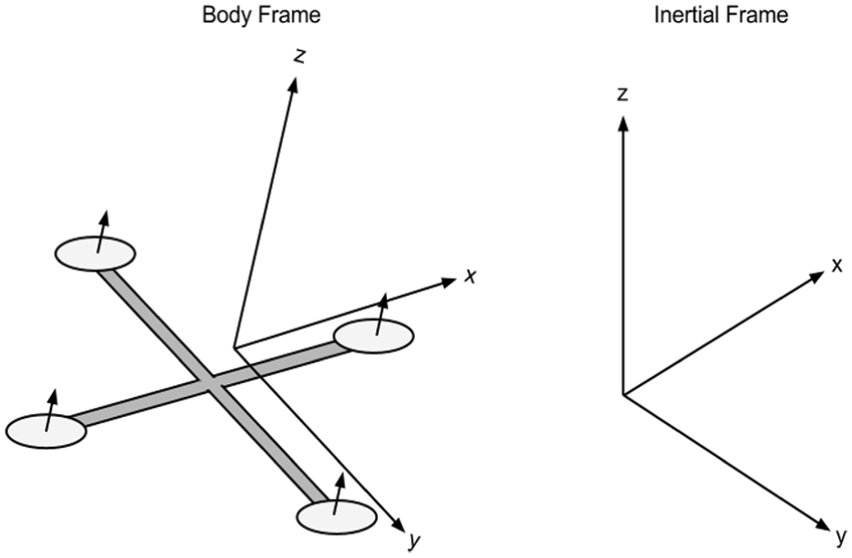
Frame of reference of quadrotor.
The linear position of the system is represented by ξ = [x, y, z]T and angular position is represented by η = [φ, θ, ψ]T. Both of the positions are derived in inertial frame with x, y, z axes for linear position while φ, θ, and ψ for angular position. To transform the parameters from body frame to inertial frame, a rotational matrix, R, is given as 3

where Cφ = cos(φ), Sθ = sin(θ), and so on. It should be noted that to convert parameters from inertial frame to body frame, R−1 is needed. Because the rotation matrix R is orthogonal matrix, it can be written that R−1 = RT. The model of quadrotor can be written in the following state space form

where X and U are representing state vectors and inputs, respectively, written as follows

and

The control inputs are given by Bouabdallah and Siegwart 4

where k and b are thrust and drag coefficients, respectively. Ω1, Ω2, Ω3, and Ω4 represent angular velocity of each rotor. The nonlinear dynamic system of quadrotor can be written as follows 3
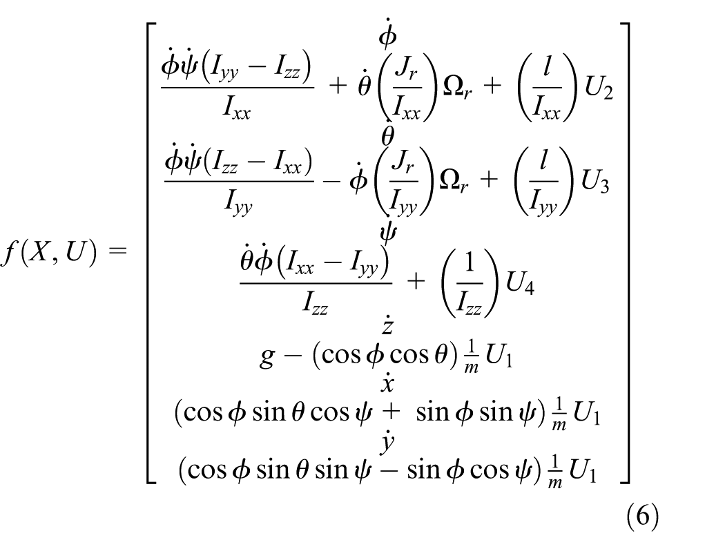
where m is mass, g is gravity, l is distance, Jr is rotor inertia. Ixx, Iyy, and Izz are airframe inertia of roll, pitch, and yaw, respectively. Angular rotation is represented by Ω r . Figure 3 illustrates that the system of angles is independent of the translation system but translation system is dependent on the angles.

Block diagram of translational and rotational subsystem.
Let us redefine the variables for simplicity as x1 = φ,
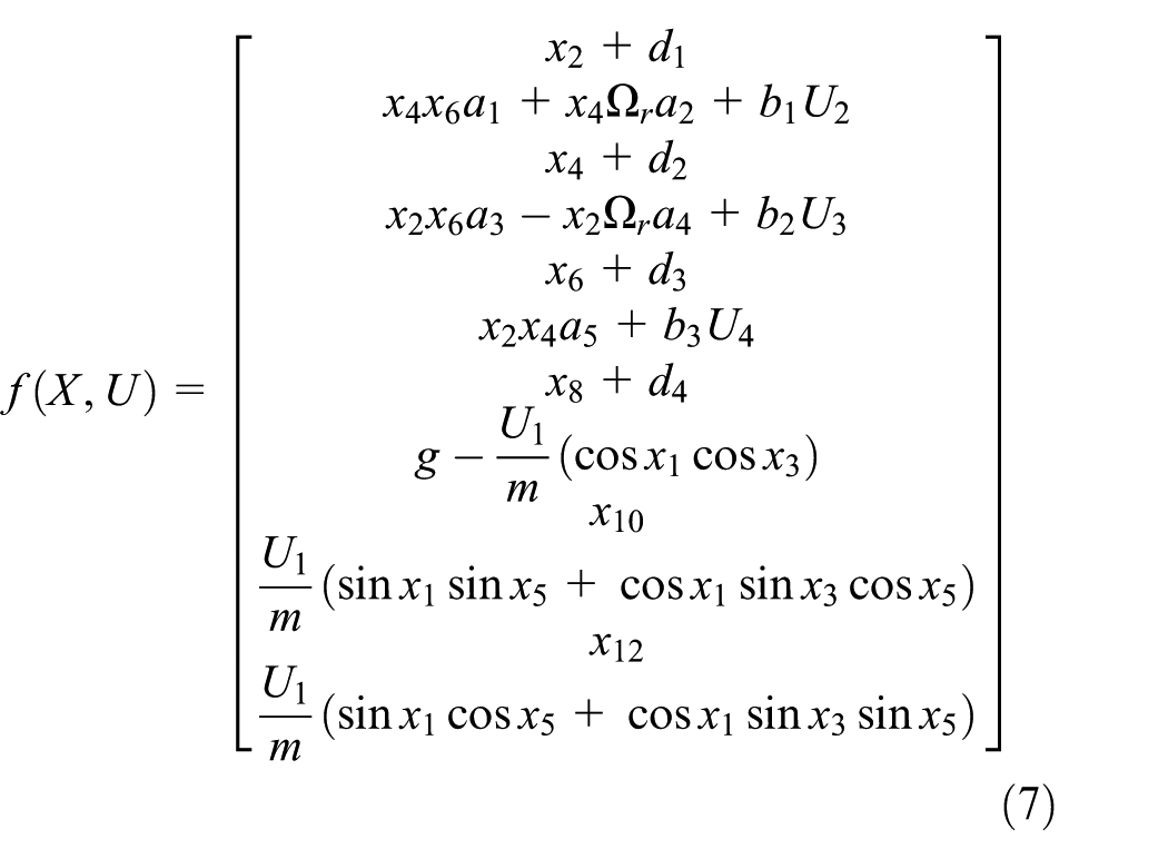
where d1, d2, d3, and d4 represent the mismatched disturbances in roll, pitch, yaw, and altitude axis of quadcopter. a1, a2, a3, a4, a5, b1, b2, and b3 are constants given in equation (8). 4 The constants in equation (7) are written as follows

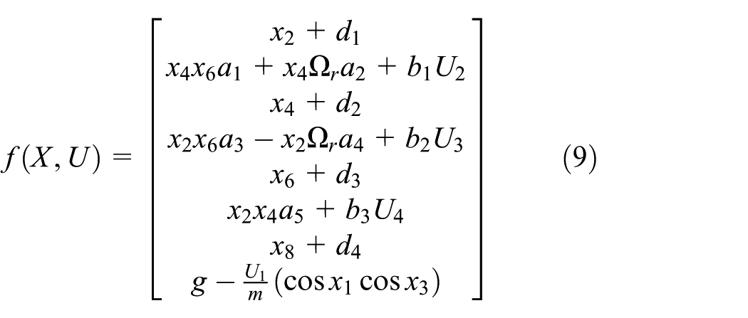
The control objective is to develop a control algorithm based on nonsingular TSMC with capabilities of disturbance rejection after integrating it with DO. However, to simplify the control design, only the attitude and height control are considered in this article. The attitude and altitude system of a quadrotor can be written as follows
For designing the control algorithm based on SMC, we need following Lemmas and Assumptions.
Lemma 1
An affine nonlinear system can be written in a generalized form as follows 32

where x ∈ R n , u ∈ R m , d ∈ R l , and y ∈ R s are the vectors of state, input, disturbance, and output, respectively. The disturbance d is a harmonic disturbance with known frequency and unknown amplitude, generated using an exogenous system give below 30

where ξ ∈ Rs is a state of exogenous system, A represents a square matrix, and C represents a row matrix with dimensions of s × s and 1 × s, respectively.
According to Chen, 33 DO proposed for rejection of disturbance generated from exogenous system (11) is designed as follows

where z is auxiliary variable, u is control input,

and
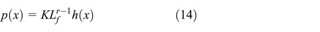
where K is a gain vector, K = [k1, k2, …, kn]
T
, to be determined, Lf represents a Lie derivative of function f(x), and r is relative degree. It has been illustrated in Chen
33
that the estimation of harmonic disturbance,

where
Lemma 2
A first-order sliding mode differentiator is designed as 52

where ρ0, ρ1, and ζ0 are representing the states, 0 and 1, are the parameters to be designed for the differentiator and f(t) is a known function. Then,
Lemma 3
If a positive definite function V (t) satisfies the inequality presented below 53

where the constant α and η are taken such that α > 0 while 0 < η < 1. Then, for any given initial condition of t0, V (t) satisfies the following inequality

and also satisfies

where tr is given as follows

Assumption 1
It is assumed that the disturbance in the system is bounded by a positive constant d*. But for the bound, it is not necessary to be known, d* = sup|d(t)| for t > 0.
Assumption 2
It is assumed that the roll angle, φ and pitch angle, θ lie in the interval
Control design based on disturbance estimation
To design the controller, we first start by assuming f(x) = [xi + 1a(x)] T , g1(x) = [0 b(x)] T , g2(x) = 1, d(t) = [d 0] T , and h(x) = x1; therefore, nonlinear system with mismatched disturbance can be derived from equation (10) as follows
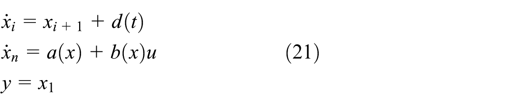
where n represents the order of the system while i is a positive integer such that i = 1, 2, 3, …, n − 1. The states are represented by xi, where i = 1, 2, 3, …, n and y is the output. Disturbance and input is represented by d(t) and u, respectively. a(x) is the function of xi and it represents states of the system containing x = [x1, x2, …, xn] T . b(x) is a nonzero function of x. Steps needed for designing a controller incorporated with DO are as follows:
Design a controller for the required parameters of stability and achieve specifications of needed performance with the supposition that disturbance is measurable.
Design a DO for estimation of disturbance.
Integrate DO with controller by replacing the term of disturbance in controller with estimated disturbance.
Control design of SMC
From equation (21), the second-order system with mismatched disturbance can be written as follows

In this article, TSMC synthesis is considered. But, while constructing a conventional terminal sliding mode controller, a problem of singularity is faced. In order to overcome the singularity problem, in Feng et al.,
49
a sliding mode surface is proposed as

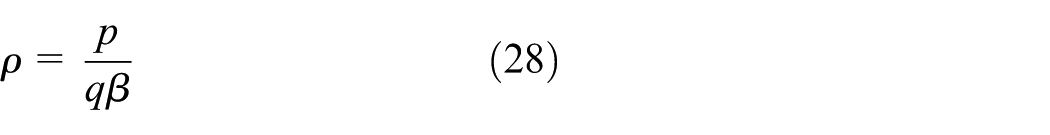
where β, p, and q are defined such that β > 0, p and q are positive odd integers designed such that 1 < p/q < 2. While

where


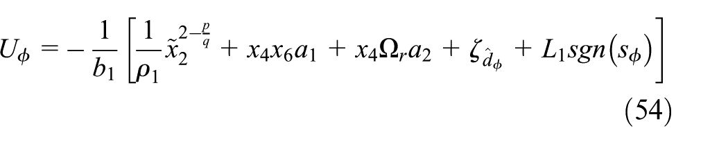
For a nonlinear system in equation (22), the proposed DO-based SMC is constructed as follows

where L > 0 is the designing constant,
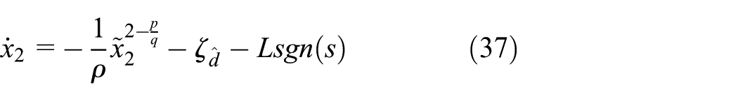
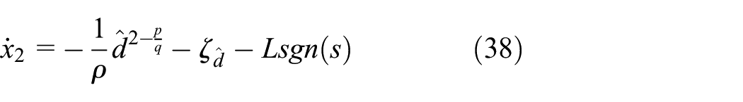
For the initial conditions as well as with the design of L such that L > 0, the control proposed in equation (27) will converge the states to zero in finite time. After constructing the SMC, it is needed to ensure the stability of the controller. To proceed, take derivative of sliding surface presented in equation (23) as

Invoking equation (22), (26), and (28) yields

The derivative of estimated DO is obtained using differentiator presented in Lemma 2; however, an error is incurred during approximation. Therefore, the derivative is written as

Invoking equation (27) yields
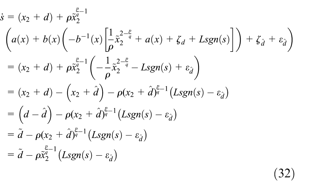
where

Taking time derivative yields

Invoking equation (32) yields

where L* = Lρ − ρε1 and Γ > ε0. Now, a constant can be designed for Lyapunov stability such that
Therefore, Lyapunov stability is ensured for the case of x2 ≠ 0. The states of the nonlinear system can reach sliding surface s = 0 is reached asymptotically. This can be proved during the second case when x2 = 0. Invoking equation (27), equation (22) yields
Substituting x2 = 0 in

Using the knowledge in Yang et al.,
54
let us define a bound D as

Furthermore, following the procedure of proof in Feng et al.,
49
for sufficiently large L > 0, it is derived that
Stability analysis of DO-based SMC
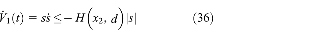
In this section, stability analysis of DO-based SMC is presented. Let us define a Lyapunov candidate function as follows

V 1(t) and V0(t) are suggested in equation (33) and Lemma 1, respectively. The former Lyapunov candidate is utilized for the stability of SMC controller, while the latter is for stability of DO. Taking time derivative of equation (41) followed by invoking equations (35) and (15) yields

The stability for the functions involved in equation (42) is presented in their respective sections, that is, the Lyapunov stability for DO is proved in Chen, 33 Lemma 1. While the stability of SMC is derived and shown in equations (35) and (40). Once the sliding mode surface is approached, we have s = 0, invoking the system dynamics in (23) yields

Now, it can be derived that

where β > 0.
Furthermore, from equation (35), it can be stated that
SMC with DO for quadrotor
UAV, quadrotor, is highly nonlinear under-actuated system. The model of quadrotor needs the controller for roll, pitch, yaw, and altitude simultaneously. The first controlling part of quadrotor is roll control based on DO which is presented as follows.
DO-based roll control
From a state space model of quadrotor in equation (7), the second-order subsystem of roll model is written where as follows

a 1 and a2 are constants given in equation (7), and Ω r is quadrotor parameter.
A generalized form of DO is presented in equation (12), which requires the calculations for p(x) and l(x). In the first step, it is needed to design a vector p(x). For roll control, using equation (13) and invoking equation (14), it is designed as follows

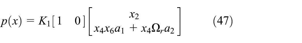

where K1 is a matrix with design constants k1 and k2,that is, K1 = [k1k2]T. The harmonic disturbance considered for the article is presented in equation (11). The matrices A1 and C1 cccrm as follows

where a111 = a122 = 0. a112 and a121 are constants such that a112 > 0 and a121 < 0, respectively. c111 represents a positive constant. Now, invoking equations (49) and (48) in equation (12), the obtained DO is written as

Resulting in

Taking time derivative and invoking equation (45) yields

Now setting

DO-based pitch control
The state space mode of pitch control is taken from the model of quadrotor in equation (7)

For pitch control, it is assumed that A2 = [0 a212; a221 0] and C2 = [c211 0]. Following similar procedure of roll control in the previous section, DO based on pitch control is derived as follows

Resulting in

Following the procedure presented in roll controller, the controller for pitch is derived as follows

where
DO-based yaw control
From equation (7), the state space model for yaw is

For yaw control, it is assumed that A3 = [0

Resulting in

SMC for yaw controller for the proposed sliding surface is calculated as

where
DO-based altitude control
From equation (7), the state space model for altitude is

For yaw control, it is assumed that A4 = [0 a412; a421 0] and C4 = [c411 0]. Hence, the DO for altitude controller is derived as

Resulting in

SMC for altitude is given as follows

where
Stability analysis of quadrotor
Now, for stability analysis of complete quadrotor altogether, let us define a Lyapunov function as follows

where Vφ, Vθ, Vψ, and Vp represent Lyapunov functions for roll, pitch, yaw, and altitude, respectively. Assuming and invoking the Lyapunov function of roll, pitch, yaw, and height yields

Taking derivative of equation (68)

Utilizing equations (35) and (42), it can be written

where

Simplifying yields

Hence, following the similar procedure of proof presented for a general nonlinear system, using Lemma 1 and the proofs in Feng et al. 49 and Yang et al., 54 the Lyapunov stability is satisfied. This completes the proof.
Simulation results
The parameters used for quadrotor are shown in Table 1. All the parameters used are converted to SI International system to have same units.
Quadrotor parameters.

For simulation study, the harmonic disturbance considered for quadrotor is given below

where j = 1, 2, 3, 4. τ decides the amplitude of the disturbance and ωj represents natural frequency of the disturbance. However, an exogenous disturbance has known frequency but unknown amplitude. 30 Therefore, in simulation study, the amplitude of disturbance is varied in each channel while keeping frequency constant. Matrices A and C required in equation (11) are derived from equation (73) as follows

It should be noted down that matrices A and C are utilized for the derivation of enhanced exogenous DO only. During performing simulations, the time-dependent function of disturbance given in equation (73) is used. Furthermore, for designing the controller p > 0 and q > 0 are odd integers chooses such that 1 < p/q < 2 shown in Table 2. Using these design parameters, controller, and DO, the quadrotor model is simulated in MATLAB, and the following results are obtained for roll, pitch, yaw, and height. The simulation results show the three stabilized angles and their controllers output as well as the disturbance estimation for each of the parameter. The initial conditions for the angles prior to the presence of disturbance are assumed to be zero, that is, φ(0) = 0, θ(0) = 0, and ψ(0) = 0. For height, it is assumed that the quadrotor is initially in the air at the height of 15 m above the ground level, that is, z(0) = 15.
SMC and DO parameters.
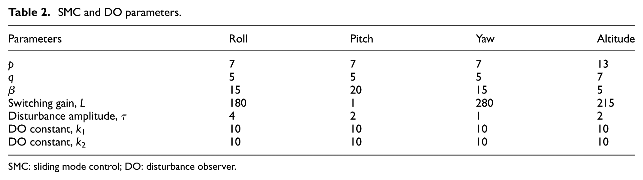
SMC: sliding mode control; DO: disturbance observer.
Simulation results of roll
Simulation results of roll are shown in Figures 4–6.
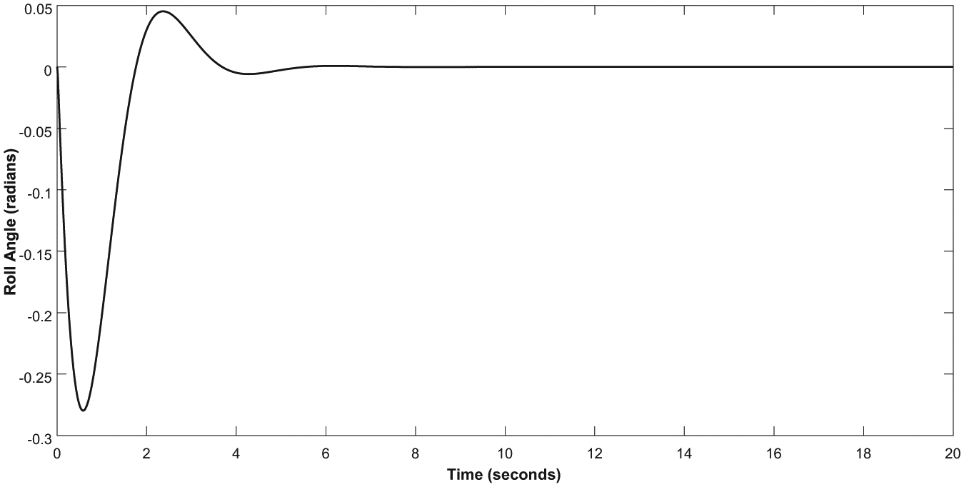
Output of roll angle.
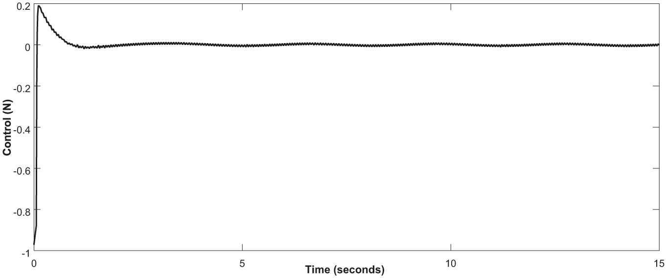
Output of roll controller.

Output of disturbance observer for roll angle.
Simulation results of pitch
Simulation results of pitch are shown in Figures 7–9.

Output of pitch angle.

Output of pitch controller.

Output of disturbance observer for pitch angle.
Simulation results of yaw
Simulation results of yaw are shown in Figures 10–12.
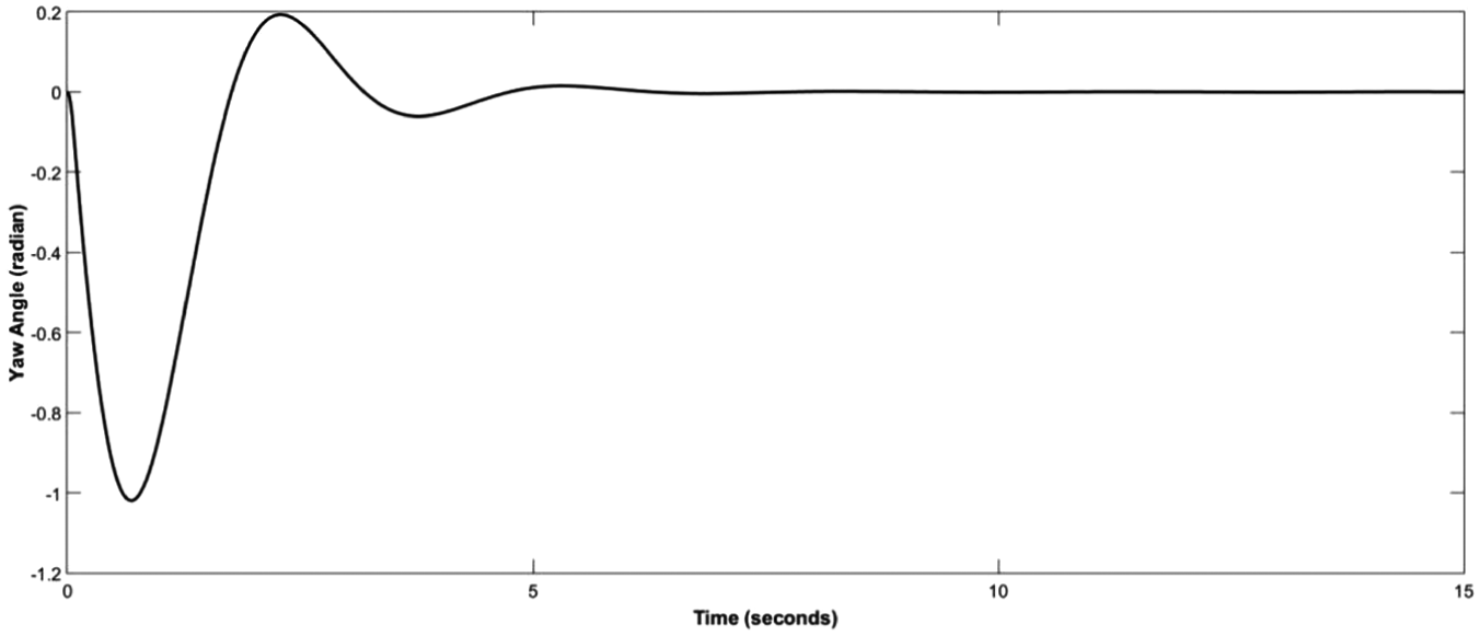
Output of yaw angle.

Output of yaw controller.
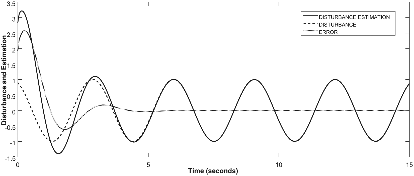
Output of disturbance observer for yaw angle.
Simulation results of altitude/height
Simulation results of altitude/height are shown in Figures 13–15.
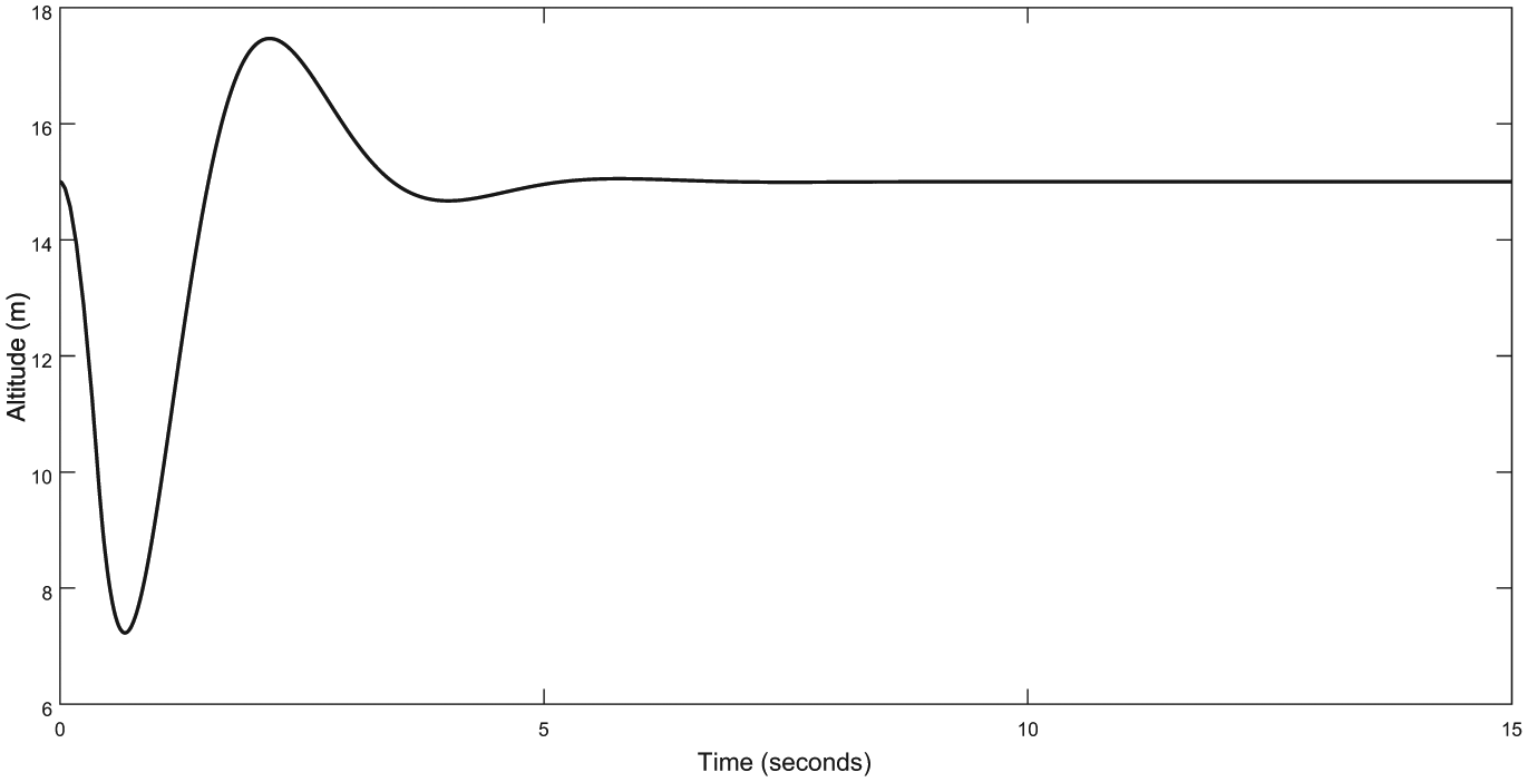
Altitude/height.
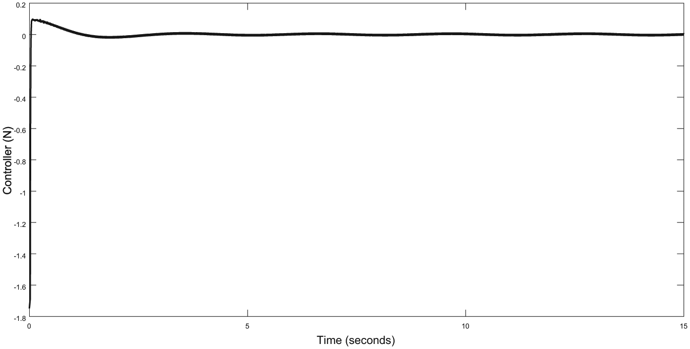
Output of altitude controller.

Output of disturbance observer for altitude/height.
Conclusion
In this research work, a modified SMC is proposed for achieving control performance of UAV, quadrotor. However, to simplify the control design, only the roll, pitch, yaw, and height control are considered. In the models of each system, mismatched exogenous disturbance has been considered for which DO is designed to estimate the disturbance. During the DO-based SMC design, two problems are faced. First, a derivative of DO is present in controller for which the states are not available. Second, singularity in the control design. The first problem is tackled by utilizing the first-order sliding mode differentiator, and for the second problem, the sliding mode surface is modified to avoid the singularity problem. After constructing the control scheme, the simulations are performed in MATLAB/Simulink tool for controller as well as DO showing that the proposed controller is effective, stable, and the performance of the system has been achieved asymptotically. Moreover, the presented research work is centered across the stabilization of quadrotor; therefore, this work can be expanded for tracking control of quadrotor.
Footnotes
Handling Editor: Chenguang Yang
Declaration of conflicting interests
The author(s) declared no potential conflicts of interest with respect to the research, authorship, and/or publication of this article.
Funding
The author(s) disclosed receipt of the following financial support for the research, authorship, and/or publication of this article: This work is supported in part by the National Natural Science Foundation of China under Grant 61573184, 61533008 and 61751219, and in part by Aeronautical Science Foundation of China under Grant 20165752049.