
Abstract
Jumping robots can be widely applied in archeology, interstellar probe, antiterrorism, and resource exploration. This article adopts the frog as the bionic object and briefly analyzes biological features and jumping movements in a complete jumping sequence of the frog. Then an equivalent six-bar mechanism model depicting frog jumping movement is built up, and the optimizing simulation of the six-bar mechanism model is performed. On the basis of the optimized results, the robot is designed and prototype is manufactured. An adaptive cascade controller is proposed to control the robot. Proportional–integral–derivative parameters of the controller are tuned online using radial basis function neural network to deal with nonlinearities of the robot. Jumping experiment demonstrates the jumping capacity of the robot and the ability of the proposed controller in tracking the desired trajectories.
Keywords
Introduction
Mobile robots have great progress in recent years and various robots, such as wheeled robots, 1 hopping robots, 2 and crawl robots, 3 have been developed. Compared to wheeled or tracked robots, jumping robots go forward via the jumping movement and own good obstacle-crossing ability. In special fields such as alien detection and resource exploration where terrains are complex, jumping robots have an attractive application prospect. Consequently, jumping robots become a hot research field of robotics and have been deeply studied these years.
Various jumping robots have been developed in the past. Raibert 4 designed a one-leg jumping robot with two degrees of freedom (DOFs). The translational DOF of the robot was to supply jumping energy, and the rotational DOF adjusted the relative angle between the body and the leg to realize dynamic equilibrium during the jumping process. M Kovac et al. 5 designed a miniature locust-like jumping robot with 5 cm height and 7 g weight. This miniature robot consisted of feet, thigh, body, infrared receiver, and lithium battery. Thigh and body were connected by two torsional springs and the jumping energy was supplied by a micromotor. To reduce the weight of the robot, gears and cams were made of polyoxymethylene (POM) material and polyether ether ketone (PEEK) was adopted for manufacturing the robot’s body. Some other bio-inspired jumping robots were developed.6–12 GH Liu et al. 6 proposed a bio-inspired hopping Kangaroo robot with an active tail via the use of the rolling SLIP (R-SLIP) model in the morphology design of the robot. QV Nguyen and HC Park 7 presented a 7g prototype of locust-inspired jumping mechanism. This ingenious mechanism adopted springs, wire, reduction gears, and a motor as the actuation components and could jump a height of 71 cm and a distance of 100 cm. J Zhang et.al. 12 designed a locust-inspired jumping robot and adopted compress torsional springs as the energy storing elements. This robot owned self-righting, steering, and takeoff angle adjusting capacities.
Compared to kangaroo and locust, the frog is one of the amphibious organisms and has good jumping and swimming capacity. Hence, presenting a novel type of frog-inspired jumping robot will lay the research foundation of the amphibious robot. Some frog-inspired jumping robots have been studied previously.13–16 G Kumar and PM Pathak 14 designed a four-bar jumping robot only imitating the rear leg of the frog. The robot was manufactured by rapid prototyping technology with a height of 43 cm when its spring was compressed and a height of 180 cm when the spring was released. The robot used a small power direct current (DC) motor as the driver, with the joint and the motor shaft connected by a rope, and the jumping movement was realized by a fast-releasing elastic element. However, this jumping mechanism mimics only the rear leg of frog and cannot realize stable landing. M Wang et al. 16 proposed a frog-inspired robot using five-bar mechanism as the jumping rear leg; however, the robot could jump a short distance because of the limited power capacity of driving motors. To overcome the relatively small torque supplied by motors, this article adopts pneumatic driving way to supply large actuating force. Pneumatic muscle actuators (PMAs) are similar to biological muscle in properties and can produce much larger force than the motors with the same weight. PMAs have advantages such as high power-to-weight ratios and compliance, and have been widely applied in bionic robots and recovery medical devices. Y Sugimoto et al. 17 designed a legged robot using PMAs. SQ Xie and PK Jamwal 18 devised a new type of wearable ankle rehabilitation robot using PMAs, which comforted patient and had a good potential application.
The novel frog-inspired bionic jumping robot in this article adopts PMAs as actuators to provide large power and mimic the biological properties of frog. First, biological structures and jumping movement characteristics of the frog are analyzed, and then the novel frog-inspired jumping robot is devised. Compared to traditional hopping robots driven by motors,1–12 especially frog-inspired robot in previous works,13–16 no complicated mechanism such as gear transmission, belt drive, or crank shaft ratchet is used in the novel robot, which means that the robot owns brief mechanism and less mechanism card death and helps improve the usage of energy. Besides, PMAs are compliant and can produce much larger force compared with motors with identical mass, which enhances the compliance of robot joints and jumping capacity.
The structure of the article is as follows: section “Mechanical design of the frog-inspired jumping robot” analyzes the biological structures of frog and the characteristics of jumping movement, and designs the mechanical structure of the robot, including rear leg and forelimb; in section “Controller design of the robot,” the controller of the robot is devised using radial basis function (RBF) neural network to tune the parameters of the controller online; experiment is performed to validate the jumping capacity of the robot and the tracking ability of the controller in section “Experiment.” The conclusions are drawn in section “Conclusion.”
Mechanical design of the frog-inspired jumping robot
Analysis of physiological structure and jumping process of the frog
Physiological structure of the frog has an important effect on its jumping characteristics and is the biological reference in designing a frog-like jumping robot. As a kind of ancient spine amphibious creature, the frog has been around for hundreds of millions of years on earth. Although there are a wide variety of frogs, the basic physiological structure is similar. The rear leg is strong and provides power in jumping and swimming, while its forelimb is small, with the function of supporting the first half of the body, changing the takeoff angle, and slowing down the impact when landing. The frog bone includes the skull, spine, and sternum, and the bone of the rear leg consists of the femur, tibiofibula, tarsal, metatarsal, and phalanx, while the bone of the forelimb consists of the humerus, radioulna, carpus, and metacarpale. 16 The rear leg is the main power source of jumping and swimming movements.
A complete jumping sequence of the frog consists of the following phases: takeoff preparation, takeoff, airborne flight, and landing.19,20 At the stage of takeoff preparation, each joint of the rear leg contracts to the greatest extent, while the forelimb adjusts the takeoff angle. At the takeoff stage, the moments of starting contracting of each joint are slightly different, among which the hip joint moves first, then the knee joint extends, and the ankle joint extends at last. The joints extend along with the rear leg extending. During the takeoff phase, the contacting area between the forelimb and the ground is gradually decreasing till the forelimb gets off the ground. The contacting area between the foot and the ground decreases till the frog enters the airborne flight phase. In the flight phase, the joints of the rear leg contract slowly and the forelimb extends gradually, which makes the frog rotate around its center mass point and prepare for the landing phase. In the landing phase, the forefoot contacts the ground first, two joints of the forelimb contract gradually, and the joints of the rear leg contract fast. The movement of each joint cushions the impact between the frog and the ground. After the foot lands, the frog adjusts its posture for the next jumping sequence. The jumping movement sequence of the frog is shown in Figure 1.

Jumping movement sequence of frog.
Mechanism design of the robot
Considering the forward jumping movement of the frog and ignoring the lateral motion, the frog can be simply abstracted to a planar six-bar mechanism (shown in Figure 2), indicating that the foot, shank, thigh, body, big arm, and small arm (i.e. hand) are modeled as a linkage, respectively. Adjacent linkages are connected by a rotational joint.

Equivalent six-bar mechanism model of frog jumping movement.
In order to provide a reference for the mechanical design of the robot, this article builds up a planar six-bar linkage mechanism in ADAMS software and optimizes the structural parameters of linkages. Length and mass of the linkages are set according to the adjustable range of the robot and characteristics of pneumatic muscles. The optimal design objective is to find the minimum value of active torques consumed in the takeoff phase. Only the takeoff phase is selected because the largest amount of energy is consumed in the takeoff phase and this phase is the critical part in the whole jumping process. The trajectories used in the optimization are shown in Figure 3. By searching the optimal point of the function, the length and mass of the linkages can be determined. The objective function built up in the ADAMS software is given as follows
where

Active joint angle trajectories in simulation optimization.
The optimized values are the lengths of the linkages of the robot: length of the foot
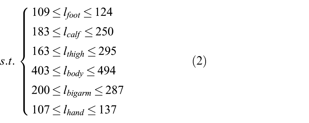
The optimal structural parameters of the linkages are shown in Table 1, and the jumping simulation with the optimal mechanism is shown in Figure 4. The acquired active torques are shown in Figure 5.
Optimal length of the bars acquired from test design.


Simulation of the six-bar mechanism model of frog-inspired robot with optimal bar parameters: (a) initial state, (b) jumping stage, and (c) flying stage.

Active joint torques in robot simulation.
Design of the rear leg of the robot
Analyzing the characteristics of frog jumping movements and the simulation results of the six-bar mechanism model, the conclusion is drawn that the rear legs are the main jumping power source. As the critical part of the frog-inspired jumping robot, the rear leg should be designed carefully. According to the physiological characteristics of the rear leg of the frog, the mechanism model of the rear leg of the robot is abstracted. The abstracting process is shown in Figure 6. PMAs are adopted to replace the musculus extensor to realize joint spread movements, while springs replace the musculus flexor to realize joint closing action.
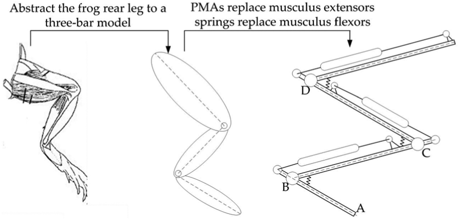
Process of building up the hindlimb mechanism.
The structure of the rear leg mechanism is shown in Figure 7. Aluminum is used to process parts of the leg so as to seek balance in light weight and high stiffness. Sensors are equipped on the leg to realize the real-time status information sampling. Angular potentiometers are installed in the ankle joint, knee joint, and hip joint, respectively, so as to measure the varied angles in the jumping process. Pressure sensors are installed at the air inlets of PMAs in order to measure the pressure inside PMAs. The type of PMA used in the hip joint is DMSP-20-180-RM-CM (nominal diameter: 20 mm, initial length: 180 mm) produced by FESTO Corporation. PMAs of DMSP-20-180-RM-CM and DMSP-20-120-RM-CM types (nominal diameter: 20 mm, initial length: 120 mm) are used to drive the knee joint and ankle joint, respectively.

(a) Model drawing and (b) prototype of the jumping leg driven by PMAs.
Design of the forelimb mechanism
The function of the forelimb mechanism is to adjust the posture of the robot and ease the landing impact. According to the geometrical parameters of the linkages acquired in simulation optimization, the forelimb mechanism is designed detailedly. The specific design process is similar to that of the rear leg mechanism—abstracting the forelimb of frog to a 2-DOF linkage mechanism and replacing the biological muscles by PMAs and springs. The abstracted 2-DOF linkage mechanism is shown in Figure 8(a). The detailed structure is displayed in Figure 8(b). The force sensor installed at the big arm is to detect the contact status between the forelimb and the ground. The types of PMAs used in the forelimb mechanism of the robot are chosen on the basis of the simulated torque curves in Figure 6. PMAs used in the shoulder joint and elbow joint are both of the DMSP-20-80-RM-CM type (nominal diameter: 20 mm, initial length: 80 mm) produced by FESTO Corporation.

(a) Schematic and (b) model drawing of the forelimb.
Design of the frog-inspired robot
On the basis of the designed forelimb and rear leg mechanism and referring to the simulated results, the robot is designed (shown in Figure 9). The robot weighs 4.66 kg with a body length of 475 mm, a body width of 330 mm, a foot length of 121 mm, a shank length of 229 mm, a thigh length of 249 mm, a big arm length of 248 mm, and a small arm length of 132 mm. The detailed information of the robot is listed in Table 2.
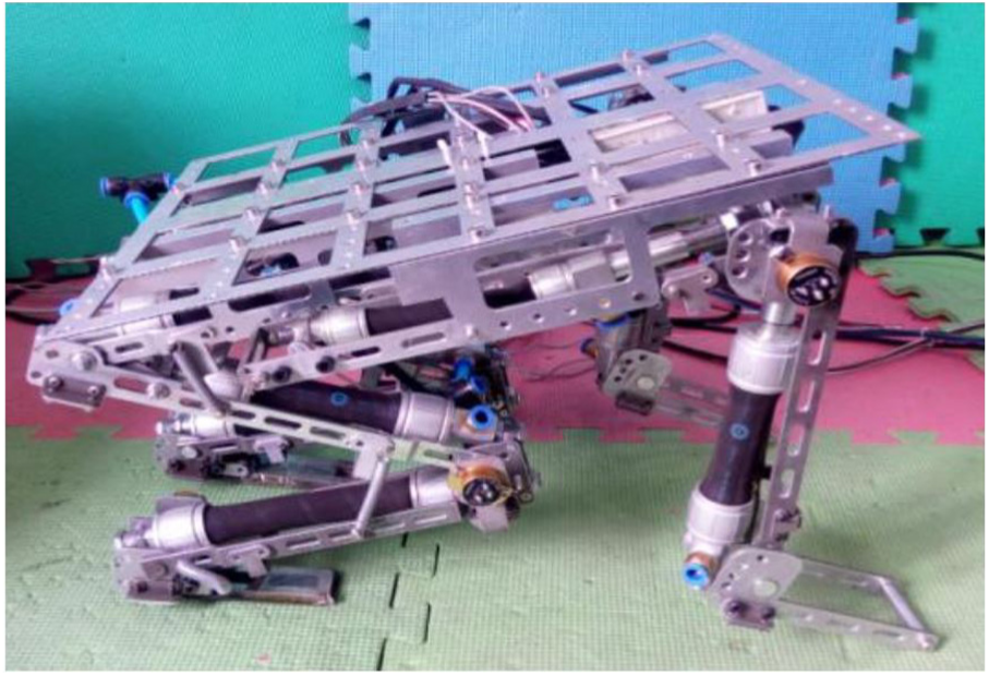
Prototype of the frog-inspired jumping robot.
Information of the robot.

PMA: pneumatic muscle actuator.
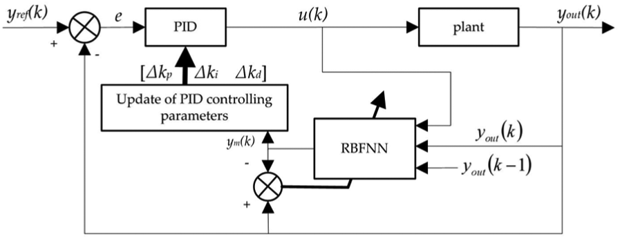
Controller design of the robot
RBF neural network online tuned proportional–integral–derivative controller for the robot
Frog-inspired jumping robot is a highly nonlinear dynamic system, which indicates that the controller must have good capacity in adaptability and self-adjustment to cope with nonlinearity of the PMA system, coupling effect among the robot joints, friction, and external disturbances. The controlling strategy of the single joint should be studied so as to realize accurately the control of the robot. Each joint of the robot uses a PMA–spring pair to provide power. As we know, PMA is a highly nonlinear system. Its nonlinearity consists of two aspects: the first is the nonlinearity caused by PMA geometry construction, such as nonlinearity of the rubber tube and nonlinearity of internal friction; the second is the nonlinearity of the pneumatic driving process. This article designs a cascade controlling strategy to implement the control of the robot joint. The controlling strategy controls the position using the outer loop and controls the pressure inside the PMA using the inner loop. An adaptive proportional–integral–derivative (PID) controller is adopted in the joint control. The parameters of the PID controller are tuned online using radial basis function neural network (RBFNN) according to the sampled real-time status information of the robot.
RBFNN has a good capacity in local approximation and can realize fast update of parameters, which meets the requirement of the real-time controlling system. It is often emerged in the controller to enhance the robustness and self-adaption capacity of the controller.
21
The structure of an RBFNN with a single output node is shown in Figure 10.

RBF neural network structure.
The PID algorithm tuned by RBFNN is shown in Figure 11, indicating that the input vector of RBFNN is
Principle of RBFNN-tuned PID algorithm.
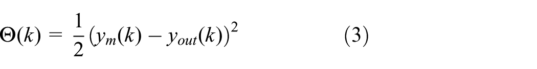
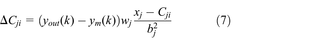
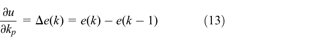
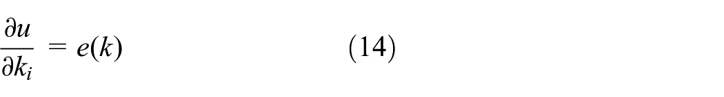
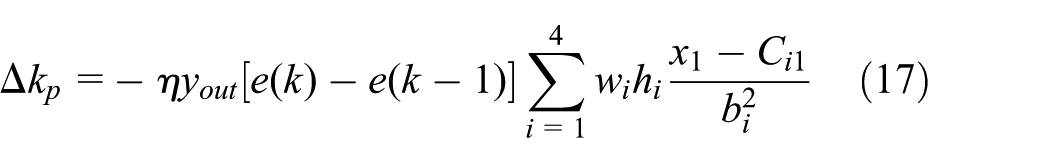
The gradient descent algorithm is adopted to tune the structural parameters of the RBFNN, by defining the cost function in equation (3), the tuning criteria of the weight wj, base width bj, and center vector Cji are given as in equations (4)–(8)


where
The instantaneous cost function used in updating the PID controlling parameters is defined as follows

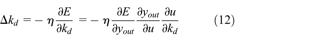
Using the gradient descent method, iterative formulae for updating the PID parameters are listed as follows


Jacobian transformation
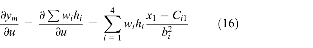
where bi and Ci1 are the base width and the center vector of the ith node in the hidden layer, respectively. Hence, equations (10)–(12) are obtained by combining equations (13)–(16) as follows


This article adopts the RBFNN-PID cascade controlling scheme to realize closed-loop control of robot joints. The controller for the robot is displayed in Figure 12 and its inner loop is shown in Figure 13. Each joint adopts an independent controller to realize its angle trajectory tracking. At different jumping stages, the dynamic characteristics of the robot are different because of different contacting statuses between the robot and the ground. Different jumping phases require different initial PID parameters which should be acquired from the actual situation. Taking the ankle joint as an example, the output of the outer loop of the cascade controller is the reference torque

Controller of the robot.

Pressure control scheme using RBF neural network-tuned PID.
Simulation
Based on the devised cascade controller of the robot, the ADAMS/MATLAB united simulation is performed. The simulated block is shown in Figure 14, where the input signals are the desired trajectories of the active joint. The outer controller is realized using Simulink subsystem and its output is the reference torque of the active joint. The inner pressure controller is also constructed by Simulink subsystem. The output of the inner loop is the contractile force of the PMA, which is to drive the robot. The dynamic module of the simulated block is transformed from the ADAMS model of the robot. Using the simulated block, the simulation is performed and the results are plotted in Figures 18–22.

ADAMS/MATLAB combined simulation.
The maximum tracking errors of the ankle joint, knee joint, hip joint, shoulder joint, and elbow joint are 4.52°, 1.81°, 5.74°, 0.28°, and 0.19°, respectively. From the comparison between the reference trajectories and the simulated trajectories, the conclusion can be drawn that the devised novel controller can deal with nonlinearities of the robot.
Experiment
Experimental setup
Principle of the constructed experimental platform is shown in Figure 15. Host computer sends the controlling command to the microcontroller and acquires status information from the microcontroller. Each joint of the robot is controlled by the microcontroller through the corresponding electrical valve. Joint angles and pressure information inside PMAs are sampled by the microcontroller and used in closed-loop control of the robot.

Schematic diagram of hardware platform.
Microcontroller adopts TMS320F28335 as the processor. The functional block diagram is shown in Figure 16. The sampled status information of the robot consists of 11 channels, including joint potentiometers, pressure sensors, and force sensors. Electrical valves are controlled by a TLC5628 chip. The cascade controller is realized in the microcontroller to achieve closed-loop control of the robot joints.
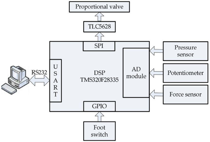
Function frame diagram of the main controller.
Experiment and discussion
The experiment in this section validates the jumping capacity of the robot using the trajectories shown in Figure 3 as the reference. During the jumping process, angular potentiometers are real-time sampled as the feedback for the outer loop control of the controlling system. Pressure sensors are used to measure the real-time pressure inside PMAs for the inner loop control. The jumping process is shown in Figure 17 indicating that the robot system is demonstrated to have the capacity in jumping. Obviously, the forefoot gets off the ground first and the tiptoe leaves the ground finally, and this process is in accordance with the jumping features of the frog.

Validation of the jumping capacity of the robot by experiments.
The sampled actual trajectories of active joints are plotted in Figures 18–22. The maximum tracking errors of the ankle joint, knee joint, hip joint, shoulder joint, and elbow joint are 14.35°, 4.78°, 10.98°, 0.5°, and 0.65°, respectively. Obviously, the tracking deviations of the ankle joint, knee joint, and hip joint are much bigger than those of the shoulder joint and elbow joint. The reason is that the rear legs of the robot are the power source of the jumping movement and move to a large extent in the motion of hopping, while the fore leg is mainly to just support the robot body during takeoff from the ground. Actual tracking deviations of each joint are obviously bigger than the corresponding simulated results, which is due to the disturbance of air pipes, machining and assembly errors, and internal friction. The comparison of the desired trajectories and actual trajectories indicates that the designed controller is feasible in controlling the robot.

Trajectory tracking performance of the ankle joint.
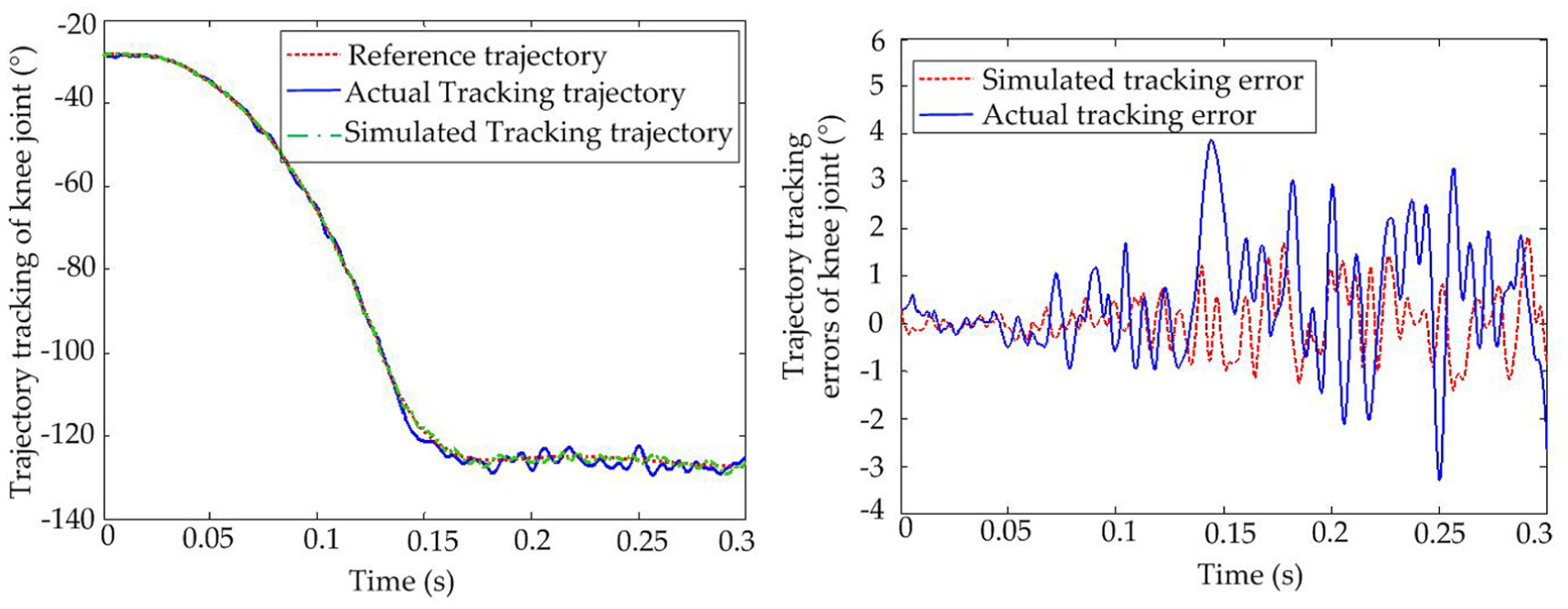
Trajectory tracking performance of the knee joint.

Trajectory tracking performance of the hip joint.
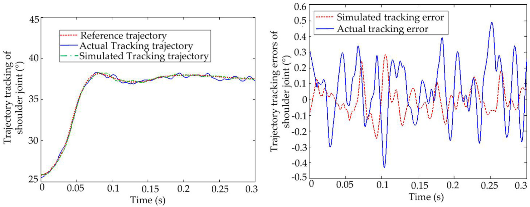
Trajectory tracking performance of the shoulder joint.

Trajectory tracking performance of the elbow joint.
Conclusion
This article analyzes the physiological structure and characteristics of the jumping motion of frog, abstracts an equivalent six-bar mechanism model depicting the frog jumping movement, and performs the optimizing simulation of the six-bar mechanism model. The rear leg and forelimb of the robot are designed using PMAs as actuators, and then the robot is constructed. A novel cascade controller is proposed for the robot. Both the outer and inner loops of the controller are tuned online by RBFNN to improve the adaptability of the controller. Simulation is performed to validate the proposed controller. Experiment demonstrates the jumping capacity of the designed robot and the tracking ability of the cascade controller. Future work will focus on how to realize soft landing of the robot in the landing phase.
Footnotes
Acknowledgements
J.Z. co-organized the work and designed the robot. M.L. and X.L. performed the experiments. J.F. and J.Z. wrote the paper.
Handling Editor: Guang Li
Declaration of conflicting interests
The author(s) declared no potential conflicts of interest with respect to the research, authorship, and/or publication of this article.
Funding
The author(s) disclosed receipt of the following financial support for the research, authorship, and/or publication of this article: This work was supported by the Natural Science Foundation of Jiangsu Province (BK20170301), the Jiangsu Province Key Development Program (BE2017647), the Science and Technology Planning Projects of Changzhou (CJ20179042), the Projects of International Cooperation and Exchanges of Changzhou (CZ20170018), the Fundamental Research Funds for the Central Universities (2016B11814), and the Fundamental Research Funds for the Central Universities (2016B12414).