
Abstract
To study the effects of different guide vane numbers on the unsteady performance of pump as turbine based on the Navier–Stokes equation and standard k-epsilon turbulence model, computation fluid dynamics technology was used to simulate the flow field in pump as turbine. The turbulent kinetic energy, unsteady radial forces, and power losses were also clarified. The results show that for turbines with a guide vane, the distribution of turbulent kinetic energy is more uniform than before, and the radial force vector distribution is more symmetrical within four quadrants. The time-domain distribution of radial force is more periodic, the number of fluctuation periods is equal to the guide vane numbers, and the dominant frequency of the radial force is equal to the blade frequency. For different guide vane numbers, the effects on the unsteady performance of pump as turbine are different. When the guide vane number is equal to 9, the distribution of turbulence kinetic energy is optimal. In addition, at an optimal flow rate, both the time domains of the radial force and the power losses of the impeller are minimal, so to the geometric parameters of the hydraulic turbine are definite, the optimal guide vane number exists.
Introduction
A centrifugal pump running in inverse mode (pump as turbine) can be applied to residual pressure energy recovery in industries. To improve the efficiency and stability of pump as turbine, many theoretical inferences, numerical simulations, and experiments have been completed, and research attention has primarily focused on the relationships of the external characteristic parameters between pumps and turbines.1–5 However, the results are not ideal and differ greatly. In recent years, studies on the optimization of turbine stator and rotor parts have been conducted by researchers, and mathematical calculation methods have been adopted to optimize the blade curves;6–10 both splitter blades11,12 and forward-curved blades
13
were used in turbine impellers in most studies. It is shown that splitter blades play a positive role in inverse mode operation such that the more the splitter blade is, the more stable the flow field is, and the lower the head of the turbine, the better the efficiency. The efficiency curve of pump as turbine with forward swept blades is flatter, and the high efficiency operating range of an impeller with forward swept blades is wider than that of a traditional turbine. Furthermore, the efficiency and stability can be improved by adding guide vanes for the pump as turbine. In a pump as turbine with a guide vane, the inflow conditions were improved,14,15 the pressure fluctuation was greatly decreased, and the vibration and noise were decreased.16,17 For different guide vane numbers, the influences on the efficiency and stability are different; fewer studies exist on guide vanes, and studies on the influence of guide vane numbers on the distribution of turbulence kinetic energy, unsteady radial force, and unsteady power losses are nonexistent. In this article, based on the verification of the accuracy of computation fluid dynamics (CFD), pump as turbine and pump with guide vane as turbine were chosen as the research objects. An unsteady three-dimensional (3D) simulation based on Reynolds time-averaged governing equations and the standard
Research objects and geometric modeling
In Yang et al.
15
a pump as turbine was chosen as the research object. At the best efficiency point, the design parameters of pump as turbine are as follows: flow rate
Main geometric parameters of the original and remodeled turbines.


Three-dimensional modeling for pump as turbine with different guide vane numbers: (a) Z0 = 0, (b) Z0 = 7, (c) Z0 = 9, and (d) Z0 = 11.
Calculation method
Unstructured grids are meshed in the 3D pro/E models of pump as turbine, and the grid independence is verified under the steady state. When the grid numbers of pump as turbine with guide vane are more than

Variation of efficiency with mesh number in Z0 = 9.
Based on the Reynolds time-averaged equations and the standard
Results and analysis
Test
The test bench for pump as turbine is shown in Figure 3. The accuracy of the numerical calculation is verified by the experiment.
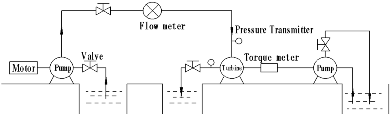
Test bench for pump as turbine.
The comparison between experimental and numerical performance curves for models Z0 = 0 and Z0 = 9 are listed in Figure 4. From the Figure 4, the performance curves of numerical prediction agree well with that of the experimental results. The efficiency of the numerical prediction is higher than that of experimental values because the numerical calculation considers the leakage loss by balancing the holes and mechanical losses when not considering the mechanical seals and bearings. At the best efficiency point, in the model of Z0 = 0, the relative errors of the efficiency and head are 3.99% and 3.19%, respectively; in the model of Z0 = 9, the relative error of the efficiency and head are 2.34% and 4.2%, respectively. It is fully proven that the turbulence model in the description of fully developed turbulent flow has good applicability, so the performance of pump as turbine can be better predicted by the numerical method. The numerical method can then be used to calculate the unsteady characteristic of pump as turbine.

Comparison between the test and numerical performance curves.
Analysis of turbulence kinetic energy under variable working conditions
The asymmetry of the volute and rotor–stator interaction causes turbulence kinetic energy concentration to appear in pump as turbine. Theoretically, the turbulence kinetic energy equals half of the product of turbulent velocity fluctuation variance and fluid mass, which generally is expressed by the physical quantity


where
In the middle section of the turbine, the contour of turbulence kinetic energy is as shown in Figure 5. From Figure 5, the kinetic energy in the volute is more uniform, the centralized kinetic energy appeared in the impeller, the volute tongue, the dynamic and static coupling interface, and so on. In the dynamic and static coupling interface, the kinetic energy is the maximum, which is caused by the rotor–stator interaction. In the model of Z0 = 0 and in the dynamic and static coupling interface, the centralized kinetic energy is obvious. The higher the flow rate is, the more obvious the concentration of kinetic energy, so at a low flow rate, the kinetic energy is less. The centralized area is also less and not obvious, but at a high flow rate, the kinetic energy is greater, while the centralized area is also greater and more obvious. At the flow rate of 0.8Q, only a small amount of kinetic energy centralized near the volute tongue and the suction surface of the impeller. At a flow rate of 1.2Q, the kinetic energy centralized in the pressure surface of the impeller; however, at a flow rate of 1.4Q, the kinetic energy centralized both in the suction surface and pressure surface of the impeller.

Contour of turbulence kinetic energy in turbine middle section: (a) Z0 = 0, (b) Z0 = 7, (c) Z0 = 9, and (d) Z0 = 11.
It is shown that the guide vane numbers have great effects on the kinetic energy. When the guide vane numbers are different, the distributions of kinetic energy in pump as turbine are also different. In Figure 5(b)–(d), the distribution of kinetic energy in volute and guide vane is very uniform. The kinetic energy in volute tongue vanished, but the kinetic energy only appeared in the dynamic and static coupling interface of the guide vane and the impeller and the pressure surface of the impeller. At a flow rate of 0.8Q, the distribution of kinetic energy is not uniform, which at 1.4Q, it is the second, and at 1.2Q, it is the most uniform. Under different working conditions, the kinetic energy in the model of Z0 = 7 is more condensed. The model of Z0 = 11 is second, while the distribution of kinetic energy in the model of Z0 = 9 is optimal; it is shown that in pump as turbine, the flow status can be changed by the different guide vane numbers, by which the kinetic energy can be distributed more uniformly. The operation of the turbine is more stable, so the optimal guide vane number exists.
Analysis of radial force vector on impeller under variable working conditions
The pump as turbine is different from pump, the radial force on the impeller exists under each working condition, and the radial force is composed of pressure and viscosity forces. In a rectangular coordinate system, the radial force can be projected in the x and y directions, so the radial force vectors FX and FY can be obtained. The radial force vector diagrams on a turbine impeller under different working conditions are shown in Figure 6, and the effect of different guide vane numbers on radial force performance was analyzed. In the coordinate system, the z-axis was selected as a rotating axis, and the radial force components were FX and FY. Figure 6 shows that in one cycle, the size and direction of radial force change at every moment, and the flow rate increases the size of the radial force, which also increases drastically. In the model of Z0 = 0, the distribution of the radial force is oval. Under different working conditions, the distribution of radial force center tends to the first and fourth quadrant, and the lower the flow rate is, the more serious the distribution. In the models of Z0 = 7, Z0 = 9, and Z0 = 11, the distribution of radial force is a star, and the radial force distributes periodically; the period number equals the guide vane number. At a low flow rate, the periodic fluctuation is greater; at a high flow rate, the periodic fluctuation is lesser. Under different working conditions, the distribution of radial force in four quadrants is more uniform, especially under the flow rate of 1.2Q and 1.4Q. The radial force in the model of Z0 = 9 is the smallest, the distribution of radial force is the most uniform. At the flow rate of 1.2Q, the distortion of radial force mainly closes to the ellipse, and the periodic fluctuation is the lightest.

Vector diagrams of radial force on impeller under variable working conditions: (a) 0.8Q, (b) 1.2Q, and (c) 1.4Q.
Analysis of time domain of radial force on impeller under variable working conditions
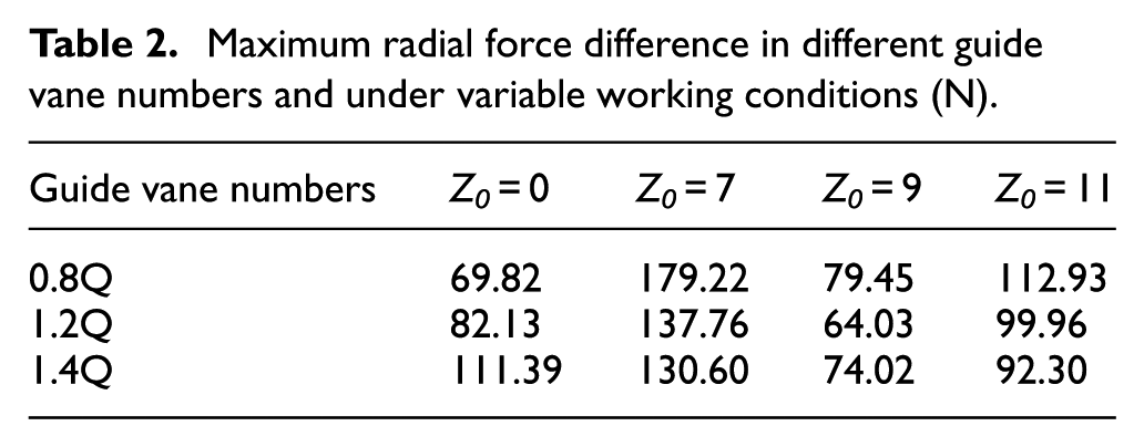
Under different working conditions, the time-domain spectrums of radial force on the impeller are shown in Figure 7. The abscissa represents the time in one cycle (the sixth rotating cycle is 0.2069–0.2483), and the ordinate represents the resultant force of transient radial force. The maximum difference of radial resultant force is defined as follow

where

Time-domain spectra of radial forces on impeller under different working conditions: (a) 0.8Q, (b) 1.2Q, and (c) 1.4Q.
Maximum radial force difference in different guide vane numbers and under variable working conditions (N).
Analysis of frequency domain of radial force on impeller under variable working conditions
Under variable working conditions, the frequency-domain spectrums of radial force on impellers are shown in Figure 8, which are transformed from Figure 7 through fast Fourier transform (FFT). The dominant frequency amplitudes of radial force under variable working conditions are shown in Table 3. The rotating speed of pump as turbine is

Frequency-domain spectra of radial forces on the impeller under different working conditions: (a) 0.8Q, (b) 1.2Q, and (c) 1.4Q.
Dominant frequencies of radial force under variable working conditions (N).

Analysis of power losses on impeller under variable working conditions
During the process of energy recycling, the pressure energies were converted into mechanical energies through the pump as turbine; then, the pump or fans were driven by these mechanical energies. For the pressure energies going through the impeller, only some of them were converted into mechanical energies; the rest were lost. According to the law of conservation and transformation of energy, the power loss equals the difference in total pressure energy and network; the formula is as follows

where
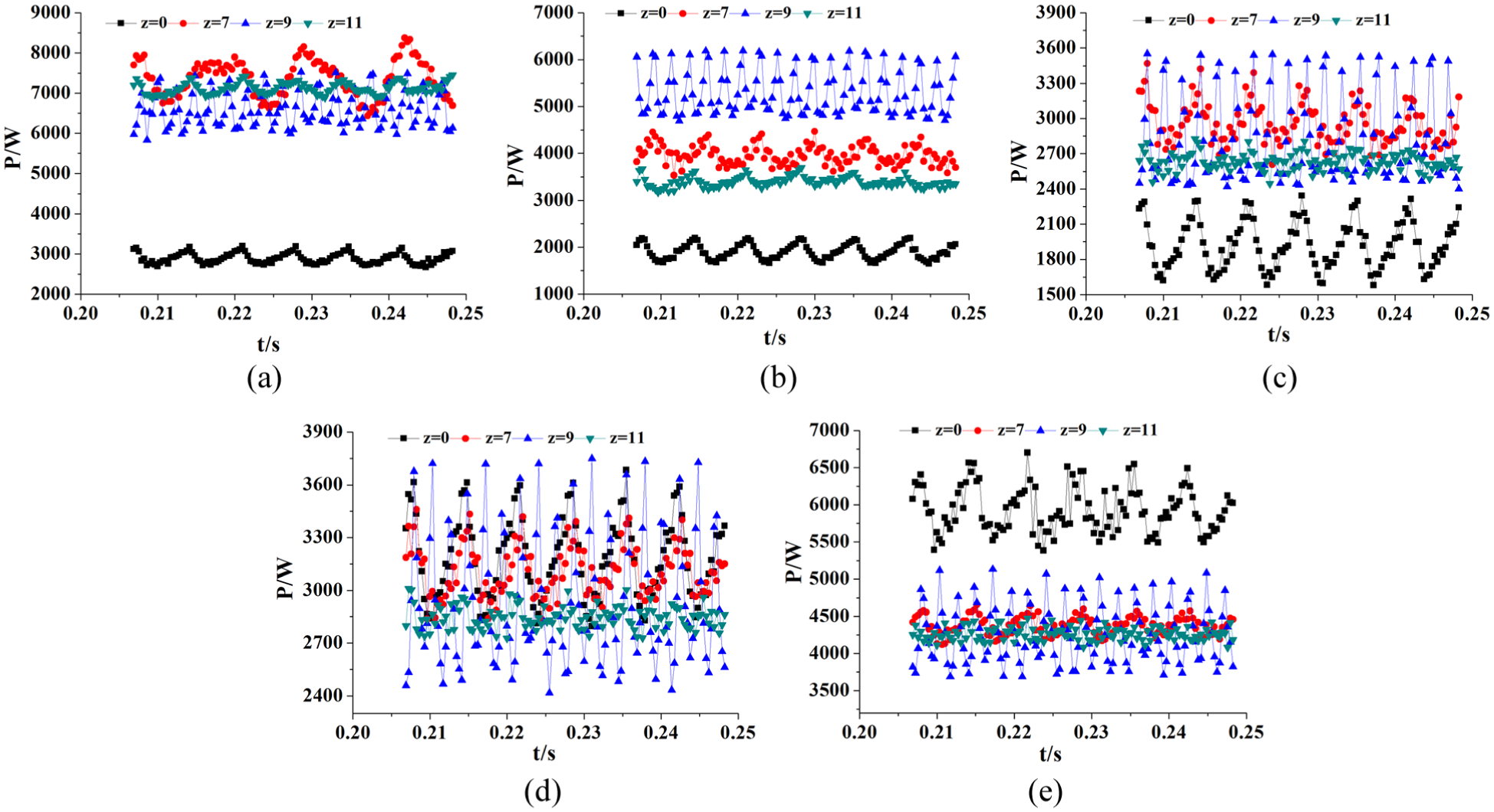
Time-domain diagrams of power losses on the turbine impeller: (a) 0.8Q, (b) 1.0Q, (c) 1.2Q, (d) 1.4Q, and (e) 1.6Q.
Average power losses on turbine impellers under different guide vane numbers (W).

Conclusion
The flow status can be improved by adding guide vanes for pump as turbine. The distribution of turbulence kinetic energy is more uniform than before, and the operation of pump as turbine is steadier. In the pump as turbine without guide vane, the center of radial force vector tends toward the first and fourth quadrants. The time-domain distribution of radial force is not homogeneous, the dominant frequency of radial force equals the rotating frequency, the power loss at the low flow rate is less, and at the high flow rate, it is greater. In the pump as turbine with guide vane, the radial force on impeller decreases, the distribution of radial force vector is more symmetrical within four quadrants, the time domain of radial force is more periodic, and the numbers of cycle equal the guide vane numbers. The dominant frequency of the radial force equals the blade frequency, the power losses at a low flow rate are greater, and the losses are less at a high flow rate. Generally, at a high flow rate, the energy recovery performance of pump as turbine is better, so adding a guide vane for the pump as turbine is helpful to reduce the power losses at a high flow rate.
When the guide vane number is equal to 9, the distribution of turbulence kinetic energy is optimal, the distribution of radial force is the most uniform, the time domain of radial force is at a minimum, and the power losses are also smaller. To a pump as turbine of other geometric parameters are definite, the optimal guide vane number exists.
Footnotes
Appendix 1
Handling Editor: Assunta Andreozzi
Declaration of conflicting interests
The author(s) declared no potential conflicts of interest with respect to the research, authorship, and/or publication of this article.
Funding
The author(s) disclosed receipt of the following financial support for the research, authorship, and/or publication of this article: This work was financially supported by the National Natural Science Fund Project of China (grant no. 51569013).