
Abstract
In this article, the contact behavior of a shrink-fitted joint in a rotor assembly at different spin speeds is studied, using the three-dimensional solid finite element approach. A custom frictionless contact model is proposed and extensively tested by means of simulation. The theory for solving pre-stressed damped eigenvalue problem is presented and implemented, and the results are presented in Campbell diagram form. Two sample rotor assemblies are studied. In addition, experimental modal analysis results of a shrink-fitted joint with various interferences are presented and numerically studied. The reduction of the interference of the shrink-fitted joint due to centrifugal forces at high-speed operation as well as the contact status are updated at each rotational speed step. The inclusion of stress-stiffening effect is studied in detail. The comparison of the Campbell diagram results with the results obtained using a commercial finite element software (Ansys) shows a good agreement.
Introduction
In high-speed machinery applications, rotor dynamic analysis is important part of the design progress. Often used one-dimensional (1D) beam element approach in rotor dynamics can represent only flexible shafts while the disks and impellers are modeled as rigid mass points. 1 These 1D elements do not take into account the cross-section deformation. In certain applications, effects of deformable shaft cross section and flexible disks, and turbine blades are required. These features enable the inclusion of the stress-stiffening effect when the total stiffness of the rotor assembly is affected by the internal stress of the component. 2 These aforementioned effects can be included when using two-dimensional (2D) axisymmetric harmonic or three-dimensional (3D) solid finite elements (FE).3–5 The use of a 2D element is usually limited to axisymmetric structures and axisymmetric loads, whereas 3D elements can be used to describe, in practice, any rotating structure.
Use of 3D solid FEs in rotor dynamic analysis allows the inclusion of nonlinear contact behavior in the study of a rotor assembly. Modern rotor assemblies used in high-speed rotating machinery can include a large number of parts with various types of joints. The contact modeling and inclusion of frictional joint-based excitations are topics that have been challenging to include in the analysis when using the conventional beam element approach. Therefore, the use of a solid 3D element is the key to study contact-based phenomena. Additional phenomena such as centrifugal stiffening or stress stiffening provides further accuracy for the FE problem. Centrifugal stiffening is derived from the centrifugal load only, whereas stress stiffening is derived from all external loads taken into consideration.
General FE contact problems are discussed in Zhang and Wang, 6 where translational joint contact with friction force is studied in 2D, and in Nejati et al., 7 where internal friction of contact on a cracked region is studied. Many publications that consider the use of traditional beam or similar 1D elements such as Santos et al. 8 and Chen et al. 9 typically present a case-dependent solution for shrink-fitted sleeve–shaft contact. The solution is mainly about tuning the sleeve material properties, as based on the theory developed.
In the literature, Jafri 10 studied the sub-synchronous rotor dynamic instability caused by the shrink fit interface. His experimental studies showed that above the first critical speed (CS) of the rotor, strong unstable sub-synchronous vibration occurred, due to the shrink fit interface. Jafri 10 stated that the unstable sub-synchronous vibration originates from friction forces which are developed by the slippage in the shrink fit interface. These slippage-induced friction forces act as destabilizing cross-coupled moments while the rotor is operating above the first CS.
Chen et al. 11 performed pre-stressed modal study of a hollow shaft assembly with shrink fits using Ansys. They used the native TARGE170 and CONTA174 contact elements of the software, and in order to verify the numerical results, experimental modal analysis (EMA) was performed. A similar study was presented in Chen, 12 where an optimal equivalent direct model was proposed for manipulating the local stiffness in the contact region, by optimizing the elastic modulus of the material. Sasek 13 studied the sensitivity of eigenvalues of flexible rotors. He proposed a method of using individual subsystems for flexible disk and shaft and connecting these two subsystems using a global coupling force vector.
Other interesting types of contacts that are used in rotating machines are studied in Richardson et al. 14 and Qin et al. 15 In Richardson et al., 14 the bolt jointed Curvic coupling is under investigation and being studied using 3D FE method. The Curvic coupling is used especially in aero-engines for transmitting torque between rotor sections using a set of matching axial teeth having similar analogy than the hirth coupling. In Qin et al., 15 bolted disk–drum joints are studied using a formulated analytical model and the FE approach using Ansys software.
The effect of stress stiffening is shown as an important aspect to take into account in any FE-based frequency analysis. Studies of Kupnik et al. 16 show how significantly the natural frequencies of a gas turbine blade can be affected by inclusion of the stress-stiffening effect. Donadon et al. 17 present the results of change in harmonic response frequencies of an ultrasonic transducer while the stress-stiffening effect is included.
Still, there seems to be a complete lack of publications regarding the 3D solid element-based contact problem of a rotor assembly analysis in the rotor dynamics field. Based on previous studies of 3D solid FE rotor assemblies with shrink fits, the presence of commercial software seems to be dominant. Since the commercial software is designed to be able to solve the arbitrary contact problem, separate contact–target elements are used. The number of equations in rotor dynamic problems of rotor assemblies using finite solid elements is typically enormous. The use of separate contact detection element will only increase the computational effort of the solution. In this article, the shrink fit joint contact behavior is studied using 3D solid FEs in a MATLAB environment using a customized methodology. A direct node-to-node frictionless contact modeling approach is introduced in this article and used in the presented studies. The experimental modal analyses are performed to manufactured test shaft assemblies, and their dynamic behavior at high-speed operation is studied. Also, the contact region nonlinearity of a conical impeller assembly is studied. In addition, the effect of stress stiffening is studied in the aforementioned cases.
Method for modeling a pre-stressed rotor assembly
The methods for obtaining damped eigenvalues in an FE system with external forces using stress stiffening approach is presented. Contact detection without the use of separate contact–target elements and the contact force calculation procedure are proposed.
Constructing structural matrices
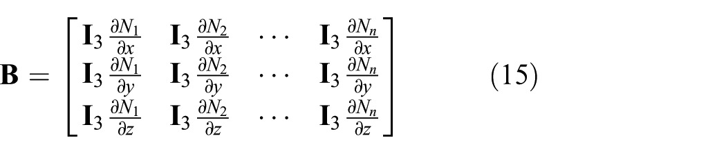
In this subsection, a short focused description of general construction of global structural mass and stiffness matrices are given. Global matrices are formed by assembling all constructed element matrices. Element mass and elastic stiffness matrices are given as follows18,19


where

where

where

The matrix of material constants for linear strain is given as follows

where


where
Pre-stressed damped eigenvalue problem
A pre-stressed damped eigenvalue problem is used to study the rotor assembly with shrink fits. The equation of motion is as follows

In order to solve a damped eigenvalue problem, the following state space matrix

where

where

where

where
In order to include the effect of closed contact in the eigenvalue problem, the contact region source–target nodes are constrained using node-to-node stiff spring connections. In eigenvalue analysis, matrix
The stress stiffening matrix

where the matrix
and the initial stress matrix

where
The deformed element stress is calculated as follows 19

where
where

where

where
Contact modeling
The interference caused by shrink fit in a rotor assembly can be modeled as either geometrical or numerical interference between shaft and sleeve bodies. The numerical approach is more convenient when, for example, the optimizing routine is used to find a suitable interference fit. When using numerical interference, the bodies are modeled without geometrical interference, and there is no penetration or gap in the contact region. In addition to other possible external forces, the contact force is applied between surfaces of contact bodies in order to yield the desired radial gap to the contact region. The radial gap is then equal to or greater than the designed radial interference, thereby allowing contact to be closed or open.
In this article, elementless frictionless contact modeling is proposed, since it enables the use of less FEs resulting in reasonably lower computational effort. The main core of elementless contact detection is the fact that the FE mesh on the contact region of both the source and target bodies, as illustrated in Figure 1, is refined so that direct node-to-node penetration detecting can be utilized. Thus, there is no need for separate contact elements. Friction forces on the contact region are neglectable due to the lack of any external axial or torsional forces allowing usage of the frictionless contact model. Studied FE problems are meshed with converging node distribution in the contact region. This means that the distance between source–target nodes is zero before applying the radial interference, if no external forces are present. This proposed node-to-node contact between the surfaces of two bodies is flexible-to-flexible contact by default.

Source and target node i of sleeve and shaft body.
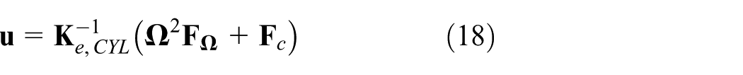
The contact model introduced in this article uses a fixed number of evaluations. At this point, it is assumed that no sliding or slipping occurs in the contact region. The contact detection is done using the cylindrical coordinate system. The deformations are mapped from the Cartesian coordinate system into the cylindrical coordinate system. After the contact force vector is calculated, it is mapped back into the Cartesian coordinate system. The first evaluation according to equation (21) takes into account all the external forces that, in these studied cases, represent centrifugal force only. The deformation vector for the first evaluation is calculated as follows

The radial distance between source–target nodes

where the superscript ′ describes the cylindrical coordinate system and the subscripts

where

where

where

where

If

The vector

Experimental results from the test shaft assembly
The test shaft assembly under study consists of a steel shaft and shrink-fitted aluminum sleeve, as illustrated in Figure 2. Certain material properties of individual components are verified by measuring mass properties and the lowest free–free natural bending mode (BM) frequencies (shafts only). For shrink-fitted joint testing purposes, three sets of test assemblies are manufactured with different radial interferences and measured by means of EMA. A scanning laser doppler vibrometer (SLDV) is used, which provides contactless measurement and does not require sensors that would add mass on the test pieces. The experimental results are shown in Table 1. Based on the measured first free–free natural BM frequencies, the radial interference in the shrink fit joint does not exert a significant effect on the natural frequencies of the test assemblies.
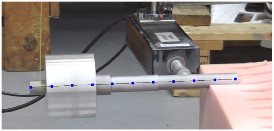
Test shaft assembly during experimental modal analysis.
Experimental results of different radial interferences of test shaft assemblies.

BM: bending mode.
Max/min value compared against the corresponding averaged value.
Component-level verification of certain material properties was performed before assembling the shrink fits. Table 2 shows the material parameters verified and applied in the numerical studies. The density of both materials used is verified by measuring the masses of all test pieces and by comparing the averaged results against known volume. The known volume is taken from the computer-aided design (CAD) model. Manufactured bodies will have marginally different dimensions due to the tolerances; however, the change in volume between test pieces was considered insignificant. The same conclusion was made while comparing the volumes of the CAD body and FE mesh. The elastic modulus of S235 is verified by measuring the first natural bending frequencies of all shaft parts. The averaged results as seen in Table 1 are set as a reference. The elastic modulus of S235 is found using the iteration loop in FE software (Ansys). The elastic modulus of 6061-T6 aluminum was not verified. The value used for elastic modulus of 6061-T6 is taken from the material data sheet. Also, Poisson’s ratios are based on material data sheets for both materials.
Material parameters used with numerical studies of test shaft assembly.

Verified parameter.
Numerical results of test shaft assembly
Based on the measured results of manufactured test shaft assemblies, the shrink fit interference seems to have a minor role in the free–free natural bending frequencies. Therefore, the case of 3 µm interference was selected for numerical studies. The studied test shaft assembly spin speed range is from 0 to 30,000 r/min with 1000 r/min increment. Another reason for selecting this particular test case is the fact that the shrink fit joint becomes loose as the rotation speed reaches 23,000 r/min, and as a result the maximum cannot be reached.
The numerical results are obtained using the proposed method, and results from commercial software Ansys Workbench 18 are obtained for comparison purposes. The contact treatment used in the MATLAB environment using the proposed method is based on the theory introduced. Results are shown as Campbell diagrams and tabulated as natural frequencies. The effect of stress stiffening is explored by studying the system with and without its influence. Thermal effects are not included in any of the presented studies.
A comparison of free–free natural BMs is shown in Table 3. The case of 3 µm interference is studied. In the case of the method proposed, results using frictionless contact with and without the initial stress stiffening, due to shrink fit interference, are given. Results obtained using both the proposed method and Ansys solution with frictional contact are compared against the averaged results of the measured test shaft assemblies. The averaging of the measured results is justified, since the effect of radial interference in the shrink fit joint does not significantly affect the natural free–free bending frequencies of the measured test shaft assemblies. The proposed method yields fairly accurate results, though Ansys reference results yield greater error compared to the measured results. Since the material properties used are the same with both modeling approaches, the contact modeling is logically the main reason for differing results. The material properties used in the numerical studies are given in Table 2.
Comparison of test shaft assembly free–free bending frequencies.

BM: bending mode.
In addition, the test shaft assembly cases 2 and 3 according to Table 1 are studied. Free–free bending frequency results are calculated with proposed method and Ansys. Between the different radial interferences, the numerical results are the same. When the stress-stiffening effect was included with the proposed method, the bending frequencies increased only by 0.02%, due to increased joint interference.
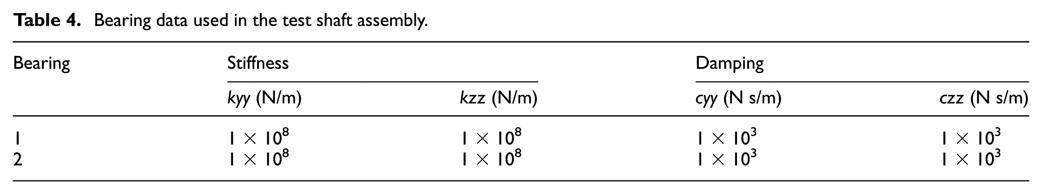
The FE-mesh of the test shaft assembly used with the proposed method is presented in Figure 3. The Ansys Workbench is used for generating FE-mesh. The mesh consist of 36,838 ten-node quadratic tetrahedron elements. The mesh size at the contact zone is 2.5 mm. The shaft diameter at the contact zone is 20 mm. By using a mesh imported from Ansys, possible differences of model discretization are avoided, and therefore differences between two modeling approaches are minimized. The length of the shaft is 260 mm and diameter of the sleeve is 80 mm. Two simple identical bearings, essentially spring-damper elements, are located at both ends of the shaft and connected to the surfaces of end planes of the shaft. The used bearing parameters are presented in Table 4.

FE-mesh of test shaft assembly.
Bearing data used in the test shaft assembly.
The Campbell diagram generated using the proposed method without the stress-stiffening effect is presented in Figure 4. It is known that the minor radial interference of 3 µm in the shrink fit joint will not hold the sleeve–shaft contact closed during the full speed range. The threshold is 23,000 r/min as seen in Figure 4. After 23,000 r/min, the contact is fully open and the resulting eigenvalues would be those of two distinct parts (shaft and sleeve) that are not comparable to the eigenvalues of the assembly. Therefore, above the threshold rotational speed, the natural frequencies are not gathered in the Campbell diagram. Also, when the contact opens, six additional rigid body modes can be obtained. The backward whirl (BW) and forward whirl (FW) mode frequencies at the threshold speed of 23,000 r/min are marked in Figures 4–7.

Campbell diagram without stress stiffening of the test shaft assembly, zero speed bending mode (BM) frequency, backward whirl (BW) and forward whirl (FW) frequencies marked.

Proposed method Campbell diagram with stress stiffening of the test shaft assembly.

Proposed method Campbell diagram of the test shaft assembly using fixed contact, critical speeds (CS), and corresponding whirling modes marked.

Ansys Campbell diagram of the test shaft assembly using frictional contact.
In Figure 5, the stress-stiffening effect is included. The stiffening effect slightly increases the frequencies of the first forward and BW modes. The Campbell diagram calculated with fixed contact, and therefore without initial contact interference nor the stress-stiffening effect is presented in Figure 6 for comparison purposes. The contact will not open at high speed due to fixed contact between shaft and sleeve. The CSs and corresponding modes are marked in Figures 6 and 7.
The Ansys Campbell diagram of the test shaft assembly is presented in Figure 7. The frictional contact with initial radial interference in the shrink fit joint is applied. As it can be clearly seen in Figure 7, Ansys does not take into account the contact opening. The results between the proposed method with fixed contact and Ansys results with frictional contact behave very similarly.
Zero speed-supported test shaft assembly frequencies of the first BM are the same using frictionless and fixed contact with the proposed method. Ansys predicts this first BM to be 9 Hz greater at zero speed. The 23,000 r/min speed was considered as one comparison point, since beyond this speed the contact treatment detects the contact fully opened. For this reason, the rest of the Campbell diagram cannot be solved when using frictionless contact with the proposed method. At 23,000 r/min, the proposed method results are consistent: the stress-stiffening effect increases whirling frequencies by 7 Hz, whereas Ansys predicts over 9 Hz greater whirling frequencies. While comparing the frictionless method results against the Ansys results, the latter ones seems constantly to be 9 Hz greater between 0 and 23,000 r/min. The results available at the upper limit of the studied speed range (30,000 r/min) are compiled in Table 5 for comparison purposes. At 30,000 r/min, only the results available using the proposed method are the results using the fixed contact model. It can be observed from the table that whirl frequencies obtained from the Ansys model are still over 8 Hz greater than the ones predicted using the proposed method. The reason for this can be in the contact modeling that Ansys uses. Similar behavior—the greater free–free bending frequencies—is shown in Table 3. Critical BW and FW speeds of the Ansys model with frictional contact are a bit over 500 r/min greater than the CSs predicted using the proposed method with fixed contact. Frictionless contact model with the proposed method does not reach the first CSs.
Whirling mode frequencies at 30,000 r/min of the test shaft assembly.

BW: backward whirl; FW: forward whirl.
Inclusion of the stress-stiffening effect will increase the mode frequencies by 7 Hz at 23,000 r/min. Also, the frequency difference due to the gyroscopic effect between BW and FW modes at 23,000 r/min using the proposed method is practically the same: average of 34.65 Hz ± 0.44%. The contact modeling method and stress stiffening clearly increase the overall stiffness of the structure.
Conical impeller assembly
The construction of the conical impeller shrink-fitted on the shaft is studied. The FE-mesh of the conical impeller assembly is presented in Figure 8. The mesh consists of 24,766 ten-node quadratic tetrahedron elements. The mesh size at the contact zone is 5.0 mm. The shaft diameter at the contact zone is 60 mm. Length of the shaft is 800 mm and the maximum diameter of the impeller wheel is 300 mm. The conical impeller of the radial kinetic compressor wheel is modeled without the blades. Only the impeller hub is included in the FE-mesh. By doing so, the size of the FE-problem can be reduced and the lower number of the lowest eigenmodes can be utilized by neglecting the low-frequency local BMs of the impeller blades. The material properties used in this study are presented in Table 6.

FE-mesh of conical impeller assembly.
Material parameters used in numerical studies of conical impeller assembly.

Two simple identical bearings, essentially spring-damper elements, are located at both ends of the shaft and are connected to the surfaces of end planes of the shaft. The stiffness and damping parameters used are the same as in the test shaft assembly example presented in Table 4. The studied speed range is from 0 to 30,000 r/min with 1000 r/min increment. The radial interference in the impeller–shaft shrink fit is 50 µm.
This particular simplified conical impeller–shaft assembly is selected because the impeller–shaft shrink-fitted joint will partially open as a function of spin speed. Partially opened contact region is illustrated in Figure 9 while the deformation is amplified for visualization purposes. The contact area will decrease while operating speed increases. This will cause a reduction of bending stiffness in this assembly.

Visualization of contact region partial opening between the conical impeller and shaft.
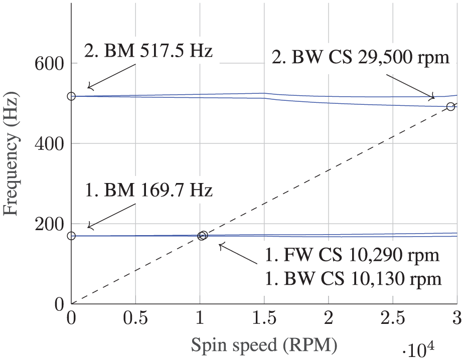
Campbell diagram of the conical impeller assembly without stress-stiffening effect is presented in Figure 10. The effect of partially opened contact is present in the Campbell diagram as the overall stiffness of the assembly is starting to reduce at 15,000 r/min. A Campbell diagram of the conical impeller assembly with stress-stiffening effect is presented in Figure 11. The stress-stiffening effect will not yield a significant stiffening effect on the BMs.

Proposed method: the Campbell diagram without stress stiffening of the conical impeller assembly.
Proposed method: the Campbell diagram with stress stiffening of the conical impeller assembly.
The Campbell diagram of the conical impeller assembly with fixed contact is presented in Figure 12 for comparison purposes. The initial interference in the shrink fit joint and the stress-stiffening effect are neglected. Since the contact is fixed, the effect of stiffness reduction due to partially opened contact is not present in the Campbell diagram. The Campbell diagram generated in Ansys is presented in Figure 13. Both the fixed joint results in Figure 11 and the Ansys results behave very similarly without having any indication of reduced bending stiffness due to partially opened contact.

Proposed method: the Campbell diagram of the conical impeller assembly using fixed contact.

Ansys Campbell diagram of the conical impeller assembly using frictional contact.
With the conical impeller assembly, the first two BMs are visible in the Campbell diagrams (Figures 10–13). The first BW and FW CS of Ansys are consistently 50 r/min greater than the ones with the proposed method. Even so, the results obtained using the proposed method with the stress-stiffening effect are actually the same as the Ansys model frequencies. Due to contact treatment applied on every speed step while using the proposed method, the contact opening is taken into account. Due to reduction in the contact surface area at high speeds, the dip in the mode lines in the Campbell diagrams (Figures 10 and 11) is present. Only the models with frictionless contact using the proposed method experience the second BW mode in the speed range studied. The stress-stiffening effect increases the second BW CS by 360 r/min.
The reason for a rather large reduction in whirl mode frequencies of the second BM using frictionless contact is explicable due to the BM shapes of the supported structure. The two lowest zero-speed BMs of the supported conical impeller assembly are illustrated in Figure 14 using Paraview visualization software. The node points of the first BM are at bearing locations. In the case of the second BM, the third node appears roughly at the center of the structure. Because the impeller–shaft joint is located roughly one quarter of the assembly length away from the other end, the joint is roughly located at the position of highest amplitude of the second BM. Also the bending deformation of the shaft is at the highest in the location of the impeller and the decreasing bending stiffness has a significant effect in this particular mode.

Conical impeller assembly lowest supported BMs at zero speed: (a) first supported BM at zero speed and (b) second supported BM at zero speed.
The zero-speed-supported conical impeller assembly frequencies are all very consistent. In Table 7, the whirling mode frequencies at 30,000 r/min are compiled. At 30,000 r/min, the first whirling mode frequencies are roughly the same, while the proposed method with stress stiffening yields greatest frequencies. The second whirling modes solved using frictionless contact with the proposed method are no longer comparable to the Ansys results, due to partially opened contact and, therefore, the reduced overall bending stiffness of the conical impeller assembly. An interesting observation is that the Ansys model with frictional contact behaves very similar to the model using the proposed method with fixed contact.
Whirling mode frequencies at 30,000 r/min of the conical impeller assembly.

BW: backward whirl; FW: forward whirl.
The partially opened contact between conical impeller–shaft will reduce the whirling mode frequencies. When comparing the second BM frequencies, the backward mode will reduce by average of 18.5 Hz and the forward mode by average of 15.9 Hz. The stress-stiffening effect will increase the stiffness of conical impeller and shaft in proximity of the contact region. Even so, the total stiffness of this structure is dominated by the robustness of the conical impeller–shaft joint. Since the contact is partially opened at full speed, the total stiffness of the structure is reduced regardless of the stress-stiffening effect. By comparing the forward and backward mode frequency difference at 30,000 r/min, the gyroscopic effect will also increase due to contact opening by an average of 10.1%.
Accuracy of contact modeling
In this section, the constraint error at the contact region achieved using the proposed contact modeling method is presented. The magnitude of the constraint error is relevant in order to achieve converged results. For comparison purposes, the results of the constraint error at the contact region calculated with Ansys are presented. Figure 15 introduces the cylindrical constraints that are used as boundary conditions for the contact treatment with the proposed method. The displacements of the assembly according to Figure 15 are constrained as follows: radial deformation is allowed while tangential deformation is restricted. Axial rigid body movement is restricted, but axial deformations are allowed. In Ansys, a cylindrical constraint that works the same way is applied.

Cylindrical constraints applied: red dot TX = 0, green dots TY = 0, blue dots TZ = 0.
For a reference solution, the test shaft assembly is selected. Rotational speed is set to be zero to ensure that no external loads are present, and thus the contact region is fully closed. The constraint error with the proposed method at the contact region is presented in Figure 16.

Constraint error at the contact region using proposed method.
The proposed contact method is based on the use of contact stiffness coefficient. Therefore, it resembles the Penalty function constraint equation method. 24 With this method, it is typical that the solution is not exact because of the penalty weight, essentially a spring coefficient, is used. The magnitude of the cells in the global elastic stiffness matrix and the penalty weight used can be used to determine the amplitude of the maximum error in the constraint. 24 As seen in Figure 16, the solution is not very focused, although the mean error is relatively small. The solution required two iterations. The cylindrical constraint utilizes approach with stiff springs that are connected to the ground. Therefore, the cylindrical constraint may also contribute a minor constraint error.
For comparison purposes, the constraint error at the contact region is calculated using Ansys. The Augmented Lagrange contact formulation is used. The constraint error in this case is presented in Figure 17.

Constraint error at the contact region using Augmented Lagrange method with Ansys.
As seen in Figure 17, the constraint error while using the Augmented Lagrange method is relatively focused, although it contains minor error. The solution required four iterations. The results of the constraint error presented in this section will give a good general understanding how different constraint method work, how many iterations they require, and how accurate they are.
Conclusion
In this article, a custom-contact model is developed and utilized for studying contact behavior at high-speed operation. The results are presented and compared to the results obtained using commercial software (Ansys). The inclusion of the stress-stiffening effect is also studied extensively. Two example cases are studied: an experimentally verified test shaft assembly with shrink fit interference joint and a conical impeller assembly. With the test shaft assembly, a number of different radial interferences are studied. Based on the results, it was noticed that the amount of radial interference in the shrink-fitted joint will not in fact change the free–free natural bending frequencies of the assembly noticeably because of the low pre-stress state. The high-speed operation of shrink-fitted sleeve was studied with the custom contact model to the point when the contact will be fully opened. At greater speeds, the solution of eigenvalue problem would yield eigenvalues of individual bodies instead of the assembly.
With the conical impeller assembly, the partial contact opening was studied and detected using a custom frictionless contact model. The same conditions are studied also using Ansys software for comparison purposes. The custom contact model proposed will update the contact status on every speed step. The results generated using this custom contact model differ moderately from the ones solved using Ansys. It seems the contact status is not updated in Ansys during the regular modal analysis where the rotational speed is used as a variable forming eventually the ingredients for generating Campbell diagram. Based on the results presented in this article, the stress-stiffening effect should be included into eigenvalue calculation particularly in cases, where relatively heavy bodies attached on the shaft using interference fittings are rotating high-speeds.
The constraint error results using the proposed method and Ansys frictional contact, as part of convergence analysis, are presented and discussed. Future studies in contact modeling area would include a transient study of frictional contact taking into account the contact opening and the friction forces as a possible source of instability.
Footnotes
Handling Editor: Hiroshi Noguchi
Declaration of conflicting interests
The author(s) declared no potential conflicts of interest with respect to the research, authorship, and/or publication of this article.
Funding
The author(s) disclosed receipt of the following financial support for the research, authorship, and/or publication of this article: The research is funded by Business Finland Grant no. 1624/31/2017.