
Abstract
A new two-terminal mechanical element named the mem-inerter described by a relation between integrated momentum and displacement is introduced as the memory counterpart of an inerter. It exhibits an individual “fingermark” featured by a pinched hysteresis loop located within the momentum-velocity plane. The mem-inerter is attached to a simple mass-spring-damper system. The system equipped with a mem-inerter is mathematically modeled, and its nonlinear vibration equation is derived. To ensure a fair performance comparison between the systems equipped with the mem-inerter and the inerter, the nonlinear mem-inerter with an appropriate helix pitch can be proved to be equivalent to the linear inerter with a fixed inertance by the fact that the systems have the same displacement transmissibility for forced response. Under such a premise, it is found that the system with the mem-inerter having positive initial displacement has better performance for free response than the system with the inerter. Furthermore, the application scenario that both systems are arranged on an inclined plane is taken as an example of the positive initial displacement. The example demonstrates that the system with the mem-inerter has significantly better transient performance than the system with the inerter.
Keywords
Introduction
In 2002, a new ideal mechanical element named the inerter was proposed by Smith. 1 With two independently movable terminals, the inerter has the nature that the acting force on the terminals is directly proportional to the relative acceleration between them. Unlike the terminals of the inerter, those of the mass are its centroid and a fixed point in a frame of reference. Therefore, in the force-current analogy, the mass is corresponding to a grounded capacitor. Since the inerter has two independently movable terminals without the need for a frame of reference, it is analogous to an ungrounded capacitor. And thus, the damper, spring, and inerter (instead of the mass) completely correspond to the resistor, inductor, and capacitor, respectively. By applying these analogs, electrical circuits can be “translated into” mechanical systems in an unambiguous manner. As a new mechanical element, the inerter brings performance improvements for various mechanical systems.2–5
The two types of inerter devices, a ball-screw inerter and a rack-and-pinion inerter, were developed in the Engineering Department at Cambridge University. 6 Such devices have been successfully used in Formula One cars. 2 Recently, this report describes a new inerter implementation7,8 which uses the moving mass of a fluid inside a helical path to provide the inertance. Swift et al. 9 proved that durability and simplicity were the main advantages of this new implementation. These devices show that inerters can be mechanically implemented in different forms.
In 2014, Chen et al. 10 introduced the concept of semi-active inerter. Hu et al. 11 provided the physical embodiment of semi-active inerter with a controllable-inertia flywheel and proved that the semi-active inerter could be realized. These research results indicate that the inertance-variable inerter can be mechanically realized, and furthermore, its inertance can be adjusted online.
In 1971, Chua 12 presented a new elementary circuit element, named the memristor, described by the relation between flux linkage and charge. Although Chua postulated the existence of the memristor, a physical passive two-terminal memristive prototype could not be constructed until 2008, when researchers at HP Labs announced that they found its engineering realization in nature. 13 In 1976, the concept of memristor was generalized to a nonlinear dynamical system by Chua and Kang; 14 as a result, a mathematical theory involving memristive systems was developed. Recently, Di Ventra et al. 15 and Yin et al. 16 extended this theory to memcapacitive systems and meminductive systems, thereby creating a whole class of mem-models. According to mechanical-electrical analogies, the corresponding mem-models of the mechanical counterparts of memristors, memcapacitors, and meminductors were created. 17 For example, a tapered dashpot is a two-terminal mechanical resistor with its resistance having a dependence on the relative displacement. 18 Another example is a rotational mechanical memcapacitor which is the subsystem comprised of the wounded part of the cable and the reel. 19 From a mechanical perspective, a tapered dashpot is the memory counterpart of a damper. Likewise, a cable-reel subsystem is the memory counterpart of an angular mass. But what is the memory counterpart of an inerter with two independently movable terminals?
In this study, a new ideal mechanical element named the mem-inerter is proposed as the memory counterpart of an inerter, and then, a scheme for the mem-inerter device is presented. The proposed scheme uses the moving mass of a fluid inside a helical path to provide the inertance, and furthermore, the helical path length changes with the relative displacement between its terminals. As a result, the inertance provided by the mass is displacement-dependent, in other words, the device is a displacement-dependent inerter. Moreover, some simulation results show that the device presents pinched hysteresis loops which have been accepted as the fingermarks of memory circuit elements in the electrical domain.12,15 The novelty of this work is that the displacement-dependent inerter is proposed to be a physical embodiment of the mem-inerter. Furthermore, in this article, the nonlinear vibration equation of a mass-spring-damper (MSD) system equipped with a mem-inerter is derived. The free and forced responses of the system are achieved by the fourth-order and fifth-order Runge–Kutta algorithm.
Displacement-dependent inertance
An internal-helix fluid inerter in Figure 1 consists of a moving piston with a helical channel surrounding its outer surface and a cylinder filled with fluid. A helical path is formed between the piston and the cylinder when the piston is inserted into the cylinder. Movement of the piston causes the fluid to flow through the helical path which generates an inertial force due to the moving mass of the fluid inside the cylinder.

Schematic of an internal-helix fluid inerter.
Let

where
For a linear inerter, equation (1) can, via integration, be transformed into the following equivalent relation

where
Let

Let

It indicates that the inertance is essentially proportional to the mass of the fluid in the channel, and square of the area ratio between the piston and the channel.
Let

where
For a set of selected parameters

Schematic of the displacement-dependent inerter.
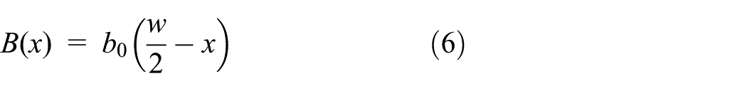
For the designed internal-helix fluid inerter device with displacement-dependent inertance shown in Figure 2, the working width of the piston, which is linearly related to the length of the helical path, is equal to
Therefore, it is needed to substitute
It indicates that the inertance at a given time is a function of the relative displacement between the terminals.
Note that the nonlinear capacitor was defined by Chua,
20
as

Obviously, according to equation (7), the displacement-dependent inerter device shown in Figure 2 cannot be modeled as the nonlinear inerter.
It is worth noticing that according to Biolek’s definition for the nonlinear inerter;
21
namely,
The mem-inerter and pinched hysteresis loops
As can be seen in the triangular periodic table of elementary circuit elements
22
, the resistor, capacitor, and inductor, together with their counterparts with memory, the memristor, memcapacitor, and meminductor, are really particular cases of a whole group of higher-order elements. By applying force–current analogies, the triangular periodic table may be transferred from electrical to mechanical domain to obtain a triangular periodic table of elementary mechanical elements as depicted in Figure 3. Such a table can be used to predict new mechanical elements just as Mendeleev’s periodic table can be used to find new chemical elements. In the table, the mem-inerter is proposed and arranged in a basic element class linking integrated momentum

Triangular periodic table of elementary mechanical elements (a mechanical analog of the triangular periodic table of elementary circuit elements by Wang 22 ).
As pointed out by Jeltsema and Dòria-Cerezo,
19
the mechanical analog of a memristor can be described by the relation between momentum

The derivative of the latter with respect to time is in the following form

By defining

Suppose one actuates the device with dimensions from Table 1, using a sinusoidal displacement
Displacement-dependent inerter details.

Figure 4(a) manifests that the inertance of the device is a function of the relative displacement, as mentioned previously. In addition, it is worthwhile to note that the function is monotonically decreasing. The mapping relation between the momentum and the velocity is multivalued except at the origin as shown in Figure 4(b). This means one is unable to define a one-to-one correspondence relationship between

Characteristic curves of the displacement-dependent inerter: (a) the curves of inertance versus displacement; (b) the curves of momentum versus velocity; (c) the curves of integrated momentum versus displacement. —— helix pitch
The concept of mem-inerter helps to differentiate the differences between the mem-inerter and the ordinary displacement-dependent inerter. Notice that the mem-inerter proposed in this research is an inerter with displacement-dependent inertance. However, not all inerters with displacement-dependent inertance are mem-inerters. Only those which exhibit pinched hysteresis loops within the momentum–velocity plane (see Figure 4) are mem-inerters. Most importantly, the mem-inerter, as a two-terminal mechanical element with memory, is completely analogous to a memcapacitor, which enriches mechanical and electrical analogies. This analog allows electrical circuits with the memcapacitor to be translated over to mechanical systems with the mem-inerter in an unambiguous manner, as a result, the mathematical theory involving memcapacitive systems can be translated directly into the mechanical context. Thus, the mathematical theory involving mem-inerter systems will be better developed in the future.
Now, review and concentrate on the six two-terminal ideal elements: inductor, capacitor, resistor, spring, damper, and inerter. Each of these elements is used to ideally and approximately describe behavior of physical devices. It is the same for the mem-inerter. As pointed out by Swift et al.,
9
in the process of modeling the fluid inerter device as an ideal element, suppose that the fluid is inelastic and dissipative effects are caused by viscosity of the fluid, the inertia generated by the fluid in the cylinder chamber and the inertia generated by the piston may be neglected. Only the inertia generated by the fluid moving in the path is considered. Such simplifications are also made in the process of modeling the device shown in Figure 2 as an ideal mem-inerter element. Besides, suppose that the mass of the fluid in the helical path is gained or lost at zero-velocity with respect to the cylinder. In this case, the momentum equation,

holds, without reference to the reactive force proportional to the velocity of the fluid which is being accreted to or expelled from the helical path. 23
MSD system equipped with a mem-inerter
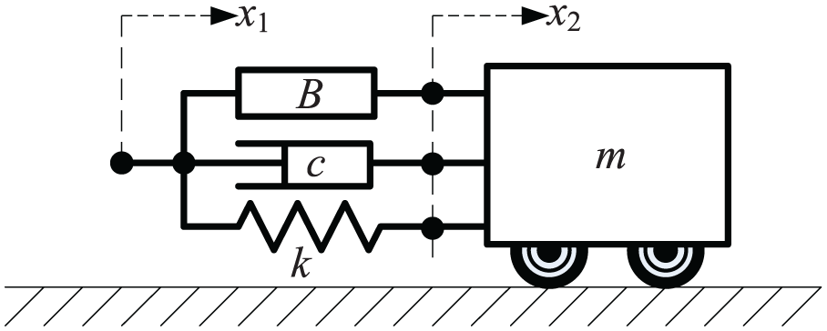
Figure 5 depicts a MSD system equipped with a mem-inerter. A cart with mass

MSD system equipped with a mem-inerter without any external force.
Indeed, in Figure 5, suppose that the system is in equilibrium position where the piston of the mem-inerter stays at central position, then the governing differential equation of the system without any external force can be written as

Substituting equation (6) into equation (12) leads to

Obviously, equation (13) is a nonlinear differential equation. If the inertance is constant, that is

Note that it is a linear differential equation corresponding to a MSD system with a linear inerter without any external force.
Consider a MSD system equipped with a mem-inerter under displacement excitation, as shown in Figure 6.
MSD system equipped with a mem-inerter under a displacement excitation.
The differential equation of the system is as follows
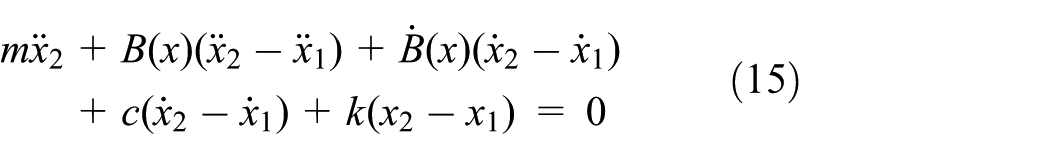
where

Obviously, equation (16) is a nonlinear differential equation. If the inertance is constant, that is,

Note that it is a linear differential equation corresponding to a MSD system with a linear inerter under displacement excitation.
Numerical examples
The system parameters,
The selected values for the numerical examples.

As a numerical example of forced response, the systems have zero initial values with the sinusoidal displacement input
In order to achieve the numerical solutions of the systems, MATLABTM is used for all computations. In view of the accuracy of the solutions, the fourth-order and fifth-order Runge–Kutta method is applied to solve these differential equations. Ode45, as a MATLAB ODE solver based on the fourth-order and fifth-order Runge–Kutta method, is used with RelTol = 10−6, AbsTol = 10−3, and MaxSep = 10−3.
Results and discussion
Forced response
For the purpose of comparing the dynamic behavior of the mem-inerter with the inerter, the forced responses of the systems for the case (1) are demonstrated in Figure 7, under the sinusoidal displacement excitation

Comparison between the dynamic behavior of the mem-inerter and that of the inerter for the case (1) under the sinusoidal excitation
Figure 8 reveals the relation between the pinched hysteresis loop and the distorted wave presented in Figure 7(a). Obviously, the pinched hysteresis loop, as the fingerprint for an element with memory, does bring about changes in dynamic behavior for the mem-inerter as mentioned above. In Figure 8, the energy expelled from or accreted to the mem-inerter
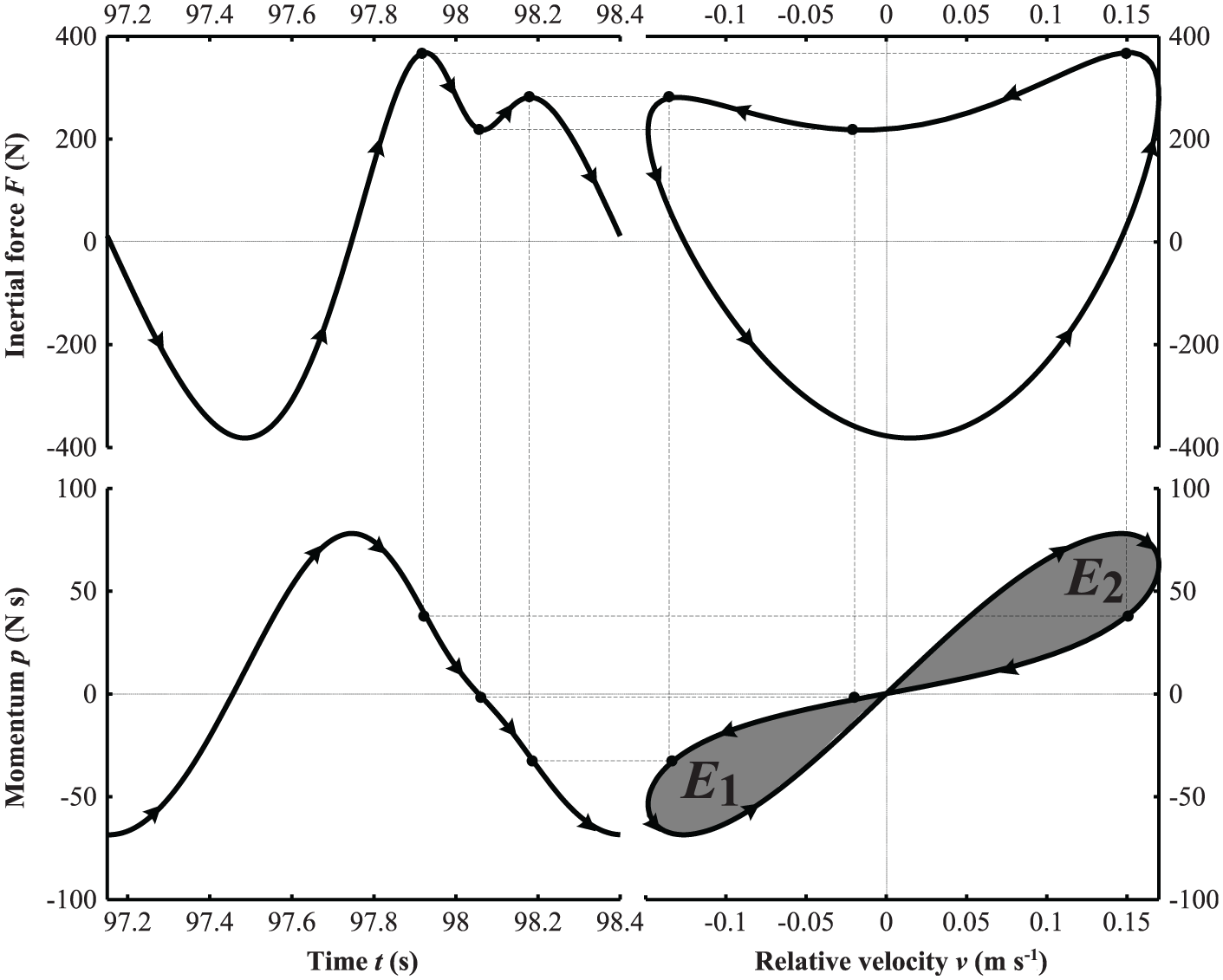
Relationship between the pinched hysteresis loop and the dynamic behavior of the mem-inerter for the case (1) under the sinusoidal excitation
The comparison of displacement transmissibility of the systems under the sinusoidal excitation for different amplitudes is performed for all cases presented in Table 2 and is illustrated in Figure 9(a)–(c). As is shown in Figure 9, the natural frequencies of both systems decrease with increasing inertance of the inerter and decreasing pitch of the mem-inerter, respectively, and so are the resonant peaks, which means improvement in the level of vibration isolation. Most importantly, Figure 9 reveals the displacement transmissibility curves of the systems for different amplitudes for all cases nearly identical, indicating that a nonlinear mem-inerter with an appropriate helix pitch is equivalent to a linear inerter with a fixed inertance. Such an equivalent relationship is necessary to ensure a fair performance comparison between the systems equipped with the mem-inerter and the inerter for free response.

Comparison between displacement transmissibility of the system equipped with the mem-inerter and that of the system equipped with the inerter for the case (1) under the sinusoidal displacement excitation of different amplitudes: (a) MSD system equipped with the mem-inerter for helix pitch Ph = 0.04 m;  MSD system equipped with the mem-inerter for helix pitch Ph = 0.06 m; ---- MSD system equipped with the inerter for inertance b = 472 kg;
  MSD system equipped with the inerter for inertance b = 237 kg;
  MSD system equipped with the inerter for inertance b = 158 kg.
Free response
For the purpose of investigating the difference between the dynamic behavior of the mem-inerter and that of the inerter for free response, the comparison between the responses of the system with the mem-inerter and those of the system with the inerter for the case (1) is carried out with different initial displacement values and is illustrated in Figure 10. Unlike the constant inertance of the inerter, the inertance of the mem-inerter defined by equation (9) depends on its relative displacement as graphically presented by the inertance-displacement curves in Figure 10(a). As a result, the momentum–velocity curves for the mem-inerter and the inerter are pinched hysteresis loops and lines, respectively, as shown in Figure 10(b). For these pinched hysteresis loops, the size of the petals (similar to the area of shaded regions
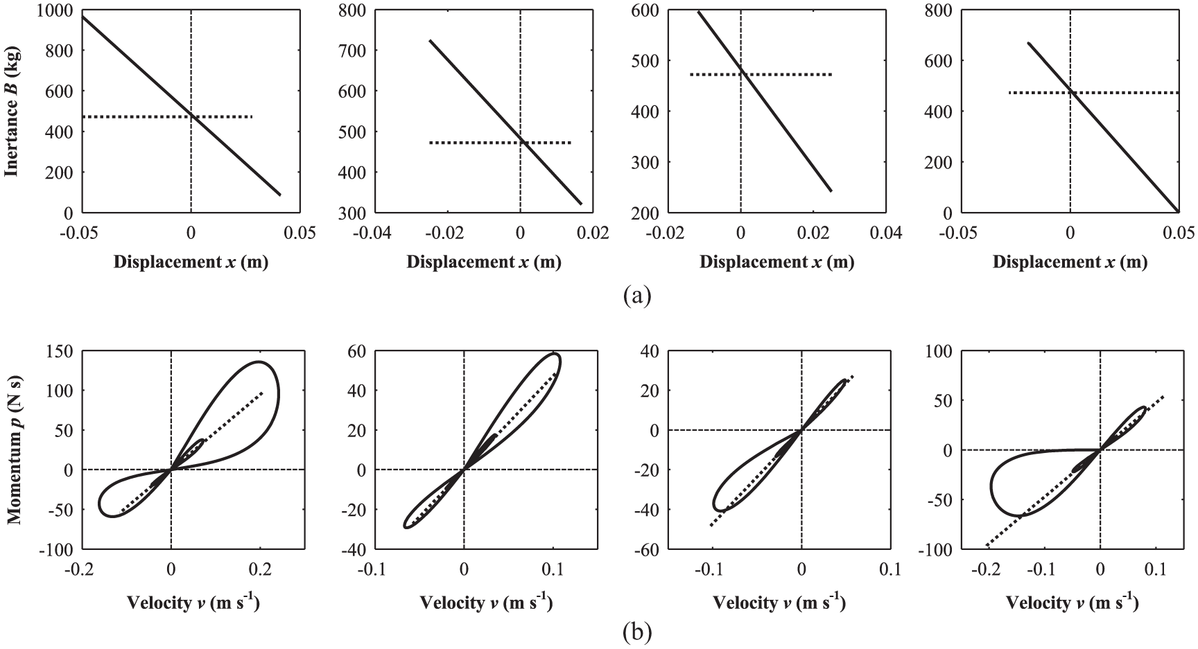
Characteristic comparison of the mem-inerter and inerter in the systems with various initial displacement values (from left to right:
The curves of displacement versus time for all cases are presented in Figure 11. As is shown in Figure 11, for free response, the system with the mem-inerter has smaller (larger) vibration amplitude than the system with the inerter when the initial displacement is positive (negative), though both systems have the same displacement transmissibility for forced response (see Figure 9). For the positive initial values, the amplitude of the system with mem-inerter compared to the system with the inerter is reduced in all cycles. In the first cycle, the amounts of vibration amplitude reduction corresponding to initial values

Comparison between free responses of the system equipped with the mem-inerter and those of the system equipped with the inerter for all cases with various initial displacement values (
An example for benefits of the mem-inerter
Vibration of a MSD system arranged on an inclined plane is a frequent topic of discussion. Especially, when the plane is perpendicular to horizontal, it becomes suspension vibration. Generally, suppose that the MSD system, equipped with a mem-inerter in Figure 6, is placed on an inclined plane with an inclination angle

MSD system equipped with a mem-inerter and arranged on an inclined plane.
The component of the gravity acting on the cart along the inclined plane can be calculated as
To indicate advantages of the mem-inerter, the comparison of displacement responses of the systems under the sinusoidal excitation of different amplitudes is carried out for the case (1) given in Table 2 and is demonstrated in Figure 13. The peak-to-peak

Comparison between
The

PTP: peak-to-peak.
As can be seen in Figure 13 and Table 3, under the sinusoidal excitation
Conclusion
A new ideal mechanical element called the mem-inerter was proposed as the memory counterpart of an inerter and arranged in an element class linking integrated momentum
For forced response, it is found that due to the pinched hysteresis loop, unlike the inerter, the mem-inerter has peculiar behaviors: half-period inequality and wave distortion in the time domain. However, the mem-inerter, on the other hand, exhibits some behaviors similar to that exhibited by the inerter; for instance, the systems equipped with the mem-inerter and the inerter have similar displacement transmissibility in the low-frequency regime, so that the nonlinear mem-inerter with a displacement-dependent inertance can be equivalent to the linear inerter with a fixed inertance. Such an equivalent relationship serves as a good basis to ensure a fair performance comparison between the systems equipped with the mem-inerter and the inerter for free response.
For free response, the MSD system with the mem-inerter compared to the MSD system with the inerter can reduce vibration amplitude under conditions of positive initial values. For negative initial values, the mem-inerter has to be rearranged in the system with its terminals exchanged.
The presented example for benefits of the mem-inerter exhibits that the MSD system equipped with the mem-inerter has significantly better transient performance than the MSD system with the inerter, when the systems are arranged on an inclined plane. Moreover, this example indicates that the mem-inerter with positive initial displacement can be fully used to improve transient performance which is beyond the reach of the inerter.
As a next step, the influence of the adhered nonlinearities such as friction and inherent damping should be considered and analyzed in the mem-inerter device for the purpose of practical application. In addition, further studies focusing on experiments and simulations based on more near-practical models should also be carried out.
Footnotes
Handling Editor: Jan Torgersen
Declaration of conflicting interests
The author(s) declared no potential conflicts of interest with respect to the research, authorship, and/or publication of this article.
Funding
The author(s) disclosed receipt of the following financial support for the research, authorship, and/or publication of this article: This work was supported by the National Natural Science Foundation of China (grant no. 51405202), the Natural Science Foundation of Jiangsu Province of China (grant no. BK20130521), the China Postdoctoral Science Foundation (grant no. 2015M570408), the Six Talent Peaks Program of Jiangsu Province of China (2013-JNHB-001), and the Startup Foundation for Advanced Professional Talents of Jiangsu University (grant no. 13JDG033).