
Abstract
Torsional movement makes the motion of a reed valve very complex and unmanageable in a rotary compressor. However, there is little information on the torsional movement of the reed valve in comparison to the valve displacement and velocity in the literature. This article investigates the torsional movement of a reed valve in a rotary compressor under different operating conditions using a fluid–structure interaction model. The phenomenon of the torsional movement of the reed valve during an operating cycle in the compressor was first studied. Then, the impact process and stress between the reed and the retainer were examined as the torsional movement was considered. The effect of the key parameters (including the asymmetric shape of the discharge chamber, eccentric reed mounting, and compressor working conditions) on the valve torsional movement was evaluated. Results showed that the impact stress of the first contact between the reed and the retainer increased as the torsional movement increased. The asymmetric shape of the discharge chamber and the eccentric mounting of the reed had a large influence on the torsional movement of the reed valve, while the rotational speed of the compressor was the key factor that significantly affected the impact stress.
Introduction
Rotary compressors are widely used in air conditioning and refrigeration systems. One of the main components of the rotary compressor is the reed valve, which controls the compressor discharge process. However, the reed valve has a high fatigue failure potential due to cyclic bending and impact caused by the cyclic nature of the compression process. This is a complex problem in the compressor since the reed impact and geometric variation could result in different contact development, reed deformation, and impact stress. 1 The reed impact occurs at some local spots ranging from the reed neck to head during the impact process between the reed and the retainer. 2 This impact is largely influenced by the torsional movement of the reed which makes the valve motion more complex and unmanageable. 3 The torsional movement worsens the impact status leading to high-potential fatigue failure of the reed valve. It is more significant when the reed reaches its highest lift, that is, at the moment of the impact between the reed and the retainer. 3
Much research work has been carried out to investigate the dynamic behavior of the discharge valve in compressors by combining the effect of valve motion and gas flow through the valve. In early studies, the gas flow was assumed as a one-dimensional (1D), quasi-static, ideal gas flow through an orifice.4,5 The gas force acting on the reed was calculated according to a pressure drop of the gas as it flows through the valve. The effective flow area and gas force acting area were obtained from either analytic formulas, 6 numeric simulations, 7 or experiments. 8 As the computational fluid dynamics (CFD) technology was developed, a three-dimensional (3D) steady flow model was further used in the analysis. 9 In these steady flow analyses, the gas inertia was ignored and the steady flow simulation could only be carried out for various fixed valve positions since it was only suitable for a fixed structure. The valve dynamics was calculated separately from the flow. The gas acting force obtained from the flow model was used as the boundary condition in the valve motion model. The reed was treated as a linear mass–spring–damper system with a single degree of freedom such as a beam 10 or a plate. 11 Then, the finite element method (FEM) was introduced to calculate the reed motion and deformation. In these steady flow models, the torsional movement of the reed was not identified separately in the analysis.
Recently, a 3D fluid–structure interaction (FSI) model has been developed to investigate the dynamic behavior of the reed valve in the rotary and reciprocating compressors. In this model, the gas flow and the valve movement are transient and coupled in the analysis. The mathematical connection between the fluid and the solid domain is given at the physical interface. The 3D transient CFD model and the dynamic reed model are solved iteratively. Compared with the abovementioned steady flow models, the FSI model provides a deep insight into the gas flow and the valve movement, as well as detailed information on the reed displacement, velocity, and impact stress. Chae and Kim developed an FSI model to study the discharge valve in a scroll compressor. In their model, the cylinder was not included and the cylinder pressure was tested and loaded into the model as the boundary conditions. 12 Wu and Wang 13 proposed an FSI model to investigate the suction and exhaust systems in a refrigeration compressor. The valve motion, the mass flow rate, and the pressure–volume diagram were obtained. Schildhauer and Spille-Kohoff performed an FSI simulation of the reed valve in a reciprocating compressor. The results showed that the contacts at the opening and closing stages were very important. 14 Pereira and Deschamps 15 examined the influence of piston on the effective flow and acting force areas of a discharge valve in a reciprocating compressor using the FSI method. Our research team has also carried out much work on the dynamic behavior of the reed valve in rotary compressors.16,17 The transient effective flow and gas acting force areas of the reed valve in a rotary compressor were analyzed through the FSI model. 16 The results showed that the impact velocity between the reed and the retainer was sensitive to the discharge port area that was partially covered by the cylinder and the roller during the discharge process. The dynamic reed behavior was further researched using the FSI model 17 to investigate the reed displacement and velocity. It was observed that the valve reed was obviously tilted. This tilting was also called the torsional movement which was visualized by Zimmermann and Hrnjak 3 in the literature. These analyses indicated that the torsional movement has high potential to cause fatigue failure of the reed valve.
In this article, the torsional movement of a reed valve in a rotary compressor is studied using an FSI model. The effect of the torsional movement on the impact process and stress is evaluated. The effect of the major parameters (including the asymmetric shape of the discharge chamber, reed eccentric mounting, and compressor working conditions) on the valve torsional movement is investigated. The analysis provides useful information for the reed valve design and optimization.
FSI model of the reed valve
Figure 1 shows a schematic diagram of a rotary compressor. A roller rotates eccentrically inside a stationary cylinder. A sliding vane maintains contact with the roller using a spring to divide the cylinder volume into a suction chamber volume and a compression chamber volume. The suction volume is always connected to the suction port, and the inside gas pressure is maintained the same as the suction pressure. The compression chamber volume is closed. As the roller rotates, the chamber volume decreases and hence the gas pressure inside the chamber increases. When the gas pressure reaches the discharge pressure, the discharge valve opens and the gas is pushed out to the discharge chamber through a discharge port. An oblique cut is machined at the location of the discharge port to enlarge the flow area and reduce the flow loss. The reed valve is used as the discharge valve in the compressor as shown in Figure 2. It is composed of a reed, a retainer, and a seat. The retainer profile is a combination of an arc and a short straight line. The reed stays on the seat when the reed valve is closed. It rises and finally contacts with the retainer when the valve opens. The main compressor and valve parameters are listed in Table 1.

A schematic diagram of a rotary compressor.

A schematic drawing of the reed valve.
Main parameters of the compressor and reed valve.

The FSI model of the reed valve is developed using the commercial multiphysics software ADINA 8.8.
18
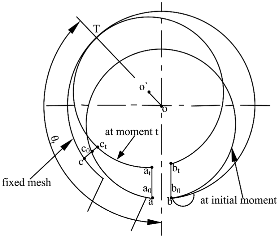
In the model, the computational zone includes the fluid zone and the solid valve zone. Figure 3 shows the fluid zone which consists of the suction port, suction volume, compression volume, and the discharge chamber. The compression volume and the suction volume are separated by the contact line between the roller and the cylinder. The movement of the roller is simulated using the moving mesh technology. The method creating the moving mesh of the suction volume and the compression volume is shown in Figure 4. The rotational angle of the crankshaft

The fluid zone in the FSI model.
Creation of the moving mesh.

Grids of the computational zone: (a) fluid zone and (b) solid zone.
The compression chamber volume and the discharge chamber are separated before the gas pressure in the compression chamber volume reaches the discharge pressure. After that, these two chambers are connected and the reed valve opens. A “pressure difference switch” is set in the model to control whether the compression volume and the discharge chamber are connected.
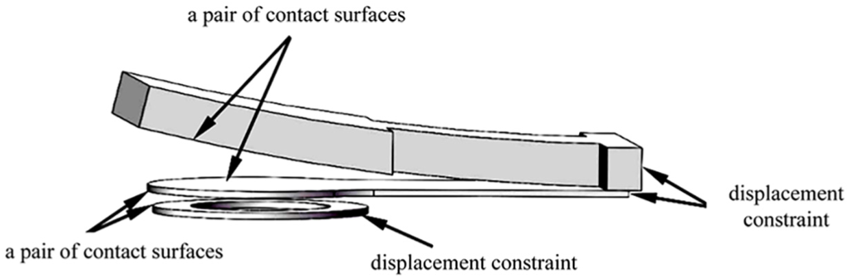
Figure 6 shows the solid zone in the model which consists of the retainer, the valve reed, and the valve seat. The reed stays on the seat when the valve closes, while it stays on the retainer when the valve fully opens. The normal contact condition is set on two pairs of contact surfaces, that is, the contact surface between the reed and the retainer, and between the reed and the seat. The contact condition is expressed by equations (1) and (2) 19


where s is the space of a pair of surfaces, λ is the normal contact force, w is the normal constraint function of the variables s and λ, ε is a small value defined by the users, it is 1.0 × 10⁻¹² in this study.
The solid zone in the model.
Table 2 lists the key assumptions made in the FSI model. The boundary conditions of the FSI model are listed in Table 3.
Key assumptions in the FSI model.

FSI: fluid–structure interaction.
Summary of boundary conditions.

FSI: fluid–structure interaction.
The FSI model of the reed valve was computed by iteratively solving the flow model and the valve dynamic model. At each time step, the flow was solved using the 3D CFD model. The flow velocity and pressure were obtained and used as the boundary conditions in the reed valve dynamic model. Then the valve motion was simulated and the valve displacement, velocity, and stress were obtained. The valve motion information was used in the flow model simulation for the next time step. The simulations continue until the difference of the results obtained in the two adjacent time steps is within a user-defined tolerance.
Results and discussion
Grid independency check
To check the grid independency, the FSI model was solved under different grid numbers. For the fluid zone, the grid numbers were set as na, nc, and nr, respectively, in the axial, circumferential, and radial directions of the cylinder. For the solid zone, the total grid number was set at 3907, 4572, and 6096. The sensitivity of the discharge angle, as well as the maximum pressure in the cylinder in relation to the grid number, was presented in Table 4. As the grid number of the solid zone increased from 4572 to 6096 at a grid number of
Grid independency check.

Observation of the valve torsional movement
Figure 7 shows displacement of the three points on the reed head to investigate the torsional movement of the reed valve at the different stages. The positions of the three points in the reed valve are shown in the upper right corner of Figure 7(a). The point 0 is at the center of the reed head. The points 1 and 2 are on the outer edge of the reed head at the oblique cut side and the cylinder side in the width direction, respectively. Figure 7(a) also shows the displacement curves of the points 0, 1, and 2 during an operating cycle, in which the movement of the reed valve undergoes four stages: closing, rising, opening, and falling. Before the rotational angle of 212°, the reed valve is closed and the pressure in the compression volume increases gradually as the rotational angle of the roller increases. As the pressure continues increasing to a value slightly higher than the discharge pressure, the reed valve starts to open. The reed valve enters the rising stage during which the reed rises until it contacts the retainer. After a few impacts and rebounds between the reed and the retainer, the valve fully opens and the reed stays on the retainer. It enters the opening stage during which the gas flows into the discharge chamber. When the discharge process is finished, the reed falls on the seat and then the valve closes again. The one operating cycle finishes and the next one starts. During these four stages, the displacement of the three points varies as the rotational angle increases.

Torsional movements of the reed valve: (a) displacement differences of the three points during an operating cycle and (b) displacement differences of the three points in the rising stage.
Figure 7(b) presents the enlarged displacement of the three points during the rising stage. In the rising stage, the displacement of point 1 is bigger than that of point 2, which indicates that the gas force acting on point 1 is bigger than that acting on point 2. Thus, the torsional movement of the reed happens on the side of point 1, that is, the side of the oblique cut.
During the opening stage, the torsional movement becomes much more significant in comparison to the rising stage. In the entire opening stage and the early falling stage, the displacement of point 1 is smaller than that of point 2 with a maximum displacement difference of 0.104 mm. The torsional movement is now reversed. This is because the discharge port is partially covered by the cylinder on the side of the oblique cut. Then the mass flow rate of the gas flowing through the side of the oblique cut is not equal to that flowing through the cylinder side of the cylinder. Therefore, the gas force acting on the reed head is uneven. The torsional movement starts to reduce in the falling stage as the mass flow rate of the gas decreases. It finally drops to a negligible level at the late stage of falling. After the valve is closed, the discharge process is finished. The compression volume starts to connect with the suction volume. During this period, the high-pressure gas in the clearance volume expands to the suction pressure and the pressure in the clearance volume is lower than that in the discharge chamber. This pressure difference causes a negative displacement at the center of the reed sink and the point 0 at the end of the valve movement (around 340°–360°).
The impact stress considering the valve torsional movement
Figure 8 shows the reed–retainer impact stress. This is the normal stress of the reed head as the reed impacts on the retainer. The moment t = 0 s refers to the first contact. It was observed that the first contact point was near point 2. This was because the displacement of point 2 was larger than that of point 1 at this stage (opening stage), and the torsional movement of the reed happens on the side of point 2 (i.e. the side of the cylinder). The impact stress was compressed stress with a negative value. Comparing the impact stress at different moments from (a) to (f), it was found that the contact points were ranging from the neck to the reed head in the length direction, as well as from the cylinder to the oblique cut in the width direction. It was found that the maximum impact stress was at the first contact. It was much larger than the impact stress of the following contacts.

The reed–retainer impact stress.
Influencing factors of the valve torsional movement
The primary cause of the torsional movement of the reed lies in the uneven gas force acting on the reed head. It is mainly caused by several factors: the asymmetric shape of the discharge chamber, the eccentric reed mounting, and the compressor working condition. In the following section, the effect of the abovementioned factors on the torsional movement of the reed is discussed. In the analysis, the rotational speed of the compressor varied from 4800 to 7200 rev/min. The suction pressure varied from 0.46 to 1.0 MPa, while the discharge pressure is maintained at 3.39 MPa.
Figure 9 shows the asymmetric shape of the discharge chamber. gv is the distance between the reed edge and the wall of the discharge chamber in the width direction. gv1 represents the distance from the oblique cut side and gv2 is the distance from the cylinder side. If gv1 and gv2 are not equal, the shape of the discharge chamber is asymmetric. In this study, gv1 and gv2 are set at 1.75 and 2.75 mm, respectively, or reverse to illustrate the effect of the asymmetric shape of the discharge chamber. The eccentric reed mounting is shown in Figure 10. The offsetting distance of the reed head e is changed from −0.5 to 0.5 mm. The positive value of e means that the reed head inclines to the cylinder side, and the negative value indicates that the reed head inclines to the oblique side.
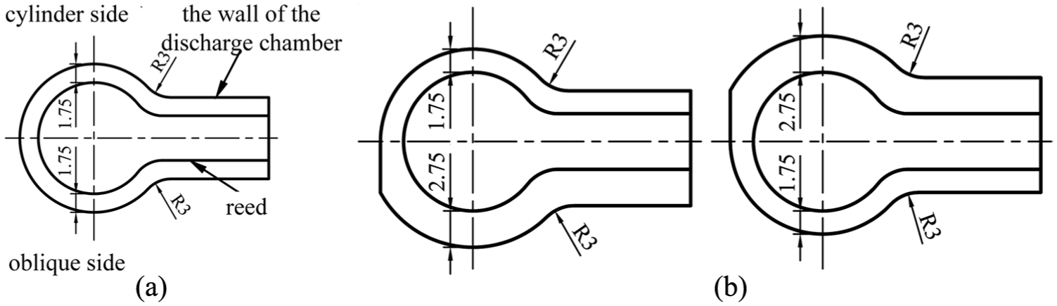
Asymmetric shape of the discharge chamber: (a) gv1 = gv2 = 1.75 mm; (b) gv1 = 2.75 mm, gv2 = 1.75 mm; and (c) gv1 = 1.75 mm, gv2 = 2.75 mm.

The eccentric reed mounting: (a) no eccentric mounting, (b) inclines to the cylinder side, offsetting distance e = 0.5 mm, and (c) inclines to the oblique cut side, offsetting distance e = −0.5 mm.
The torsional movement of the reed valve was calculated using the FSI model as the abovementioned three factors varied, respectively. To evaluate the torsional movement, the displacement difference of point 1 and point 2 is compared at the displacement of 1.8 mm for point 0. The detailed results are listed in Table 5.
The torsional movement of the reed under different working conditions (h0 = 1.8 mm).

The effect of the asymmetric shape on the torsional movement was studied in the models #1, #2, and #3. In model #1, the shape of the discharge chamber is symmetric, while the asymmetric shapes are set in models #2 and #3. It was found that in model #1 the displacement difference between point 1 and point 2 is 0.018 mm. The torsional movement of the reed existed in the oblique cut side. Comparing the displacement difference between models #1, #2, and #3, it was observed that if gv1 > gv2 the torsional movement of the reed still existed on the oblique cut side and became more severe. On the other hand, the torsional movement changed from the oblique cut side to the cylinder side if gv1 < gv2. But the torsional movement was not as severe as that in model #2. From the design point of view, gv1 should be slightly smaller than gv2, which might be able to reduce torsional movement.
In models #4 and #5, the reed is eccentrically mounted, and the offsetting distance of the reed head is set at 0.5 and −0.5 mm. Comparing the displacement difference between models #1 and #4, as the reed head inclined to the cylinder side, the torsional movement of the reed changed from the oblique cut side to the cylinder side and the displacement difference between point 1 and point 2 becomes bigger. This indicated that the torsional movement became stronger. On the other hand, as the reed head inclined to the oblique cut (i.e. model #5), the torsional movement of the reed still occurred on the oblique cut side; however, it became much more severe.
The above analyses indicated that the asymmetric shape of the discharge chamber or the eccentric reed mounting had large influences on the torsional movement of the reed. Particularly for the factor of the eccentric reed mounting, even if the offsetting distance was 0.5 mm, the displacement difference between point 1 and point 2 increased 4–6 times.
The effect of the working condition on the torsional movement is studied in models #6 and #7. In model #6, as the suction pressure is changed from 1.0 to 0.46 MPa, the torsional movement increased from 0.018 to 0.068 mm. Meanwhile, the pressure ratio increased and hence the discharge angle increased from 209.5° to 250.0°. Compared with model #6, as the rotational speed increased from 4800 to 7200 rev/min in model #7, the torsional movement increased from 0.068 to 0.091 mm. These comparison results showed that the torsional movement of the reed became more severe as the pressure ratio or the rotational speed increased.
It can also be seen from Table 5 that the impact stress of the first contact between the reed and the retainer was closely related to the degree of torsional movement of the reed. The impact stress of the first contact increased as the severity of the torsional movement increased. When the reed was eccentrically mounted, the impact stress of the first contact between the reed and the retainer increased sharply. The most significant influencing factor of impact stress was found to be the rotational speed of the compressor. As the rotational speed increased, both the gas flow velocity through the valve and the gas force acting on the reed increased, which largely affected the impact stress.
Conclusion
In this article, the torsional movement of the reed valve was studied using the FSI model. The phenomenon of the torsional movement of the reed valve in an operating cycle of a rotary compressor was presented and discussed. The results showed that the torsional movement of the reed was more significant during the entire valve opening stage and early stage of falling. It was insignificant at the late stage of falling. The FSI model was further used to investigate the impact stress and effects of the key parameters on the torsional movement. Some important conclusions are detailed below:
The maximum impact stress between the reed and the retainer occurred at the first contact and was much larger than the stress in the following contacts. Due to the torsional movement, the first contact point was near the outer edge of the reed on the side of the cylinder.
The comparison results showed that the asymmetric shape of the discharge chamber, the eccentric reed mounting, and the compressor rotational speed had significant effects on the torsional movement. Particularly for the factor of the eccentric reed mounting, even if the offsetting distance was 0.5 mm, the torsional movement increased 4–6 times.
The impact stress of the first contact between the reed and the retainer increased as the severity of the torsional movement increased. The most significant factor influencing the impact stress was the compressor rotational speed.
The sensitivity study of the valve torsional movement identified the need to control the asymmetric shape and the eccentric reed mounting in the design and optimization of the reed valve in the rotary compressor.
Footnotes
Appendix 1
Handling Editor: Hiroshi Noguchi
Declaration of conflicting interests
The author(s) declared no potential conflicts of interest with respect to the research, authorship, and/or publication of this article.
Funding
The author(s) disclosed receipt of the following financial support for the research, authorship, and/or publication of this article: The authors acknowledge the financial support by the National Science Foundation of China (No. 51676150).