
Abstract
At present, owing predominantly to advances in measurement technology, microprocessor control and development of smart materials have witnessed a widespread adoption of semi-active damping systems based on magnetorheological fluid technology into everyday life. An important class of systems which utilize magnetorheological technology is constituted by vehicle vibration systems. These systems are generally equipped with different numbers of reciprocating or rotary dampers filled with magnetorheological fluid. Dampers and their properties are controlled by an electronic controller with embedded control algorithm. In this article, a simplified model of an off-road vehicle equipped with a real-time controlled semi-active suspension system with magnetorheological dampers is presented. In addition, a simple algorithm employed to control them is described. Algorithm efficacy has been verified by means of conducting numerous road and off-road experiments employing Honker 2000 vehicle. The main goal of this article is to present simplified yet efficient methods for controlling changes in properties of suspension of an off-road vehicle with magnetorheological dampers. These properties are controlled by an optimization algorithm responsible for an optimal selection of friction in magnetorheological dampers. The algorithm allows for a substantial improvement of the performance of an off-road vehicle suspension.
Introduction
In recent times, mechanical structures with embedded active and adaptive absorbers or dampers, built with the use of smart materials, have received much attention in the area of vibration and impact control of structures The most common smart materials include magnetorheological fluids (MRFs), electrorheological fluids (ERFs), piezoelectric (PZ) materials, shape memory alloys (SMA), or vacuum packed granular particles (GM). A dominant feature of these materials is that their physical properties can be altered relatively easily under the influence of an external signal, like magnetic or electric field, temperature, pressure, or underpressure. Such unique features of smart materials, as well as observed rapid progress in their manufacturing, have led to their common adoption in everyday life.
At present, the most commonly used intelligent materials applied in the construction of semi-active vehicle suspensions are MRFs. Jolly et al. 1 and Carlson and Goncalves 2 proposed one of the first suspension types with controlled magnetorheological dampers (MRDs). The subject is still up to date, being undertaken by scientists conducting experimental and numerical research on suspensions of vehicles equipped with this type of dampers.3–5
Recently, many other investigations (cf. previous studies6–10 for example) provided additional know-how on developing effective vehicle, train, or aircraft active or semi-active suspension systems with the use of different smart materials. It should be noted that many modern active and semi-active vibration or isolation systems utilize also standard materials, that is, hydraulic dampers controlled by electromagnetic or piezoelectric valves.11,12 Still, all of these solutions are employed in a relatively small number of passenger vehicle suspension systems, where their dissipative features are adapted in real time to the current vehicle load and road conditions.
In off-road vehicles, apart from the need to maintain passenger comfort, the stability of the vehicle during various maneuvers is of paramount importance. The vehicle stability depends strongly on two factors: (1) the forces coming from the ground forces acting through wheels and (2) the forces due to the inertia of the vehicle. Hence, for the operation of a suspension system assuring vehicle stability, it is absolutely necessary to maintain adequate levels of forces between vehicle wheels and ground surface. These vertical forces are responsible for proper adhesion of wheels to the ground and for the transmission of driving power through wheels. In the case of loss of contact between wheels and the ground, there is a very limited opportunity for the vehicle to be influenced by means of controlling friction forces or to maintain adequate value of driving power at wheels. Therefore, in the case of off-road vehicles, it is particularly important to minimize variation of the value of vertical wheel forces.
The main goal of this work is to continue investigation issues associated with the proposed control algorithms 13 incorporating the criterion of minimizing variations in vertical wheel forces and its versatility for use with different types of vehicles. In Makowski and Knap, 13 it was demonstrated that the algorithm is quite efficient in the case of a light van (Ford Transit). Here, the case of an off-road vehicle (Honker 2000) is investigated where the conditions of excitations, for example, due to vehicle speeds and wheels’ displacements, are markedly different. We present the results of the experimental off-road investigations of the vehicle suspension system equipped with MRDs, the numerical model of the vehicle as well as criteria of optimization used in the control algorithm, and the results of numerical simulations.
As the developed algorithm seems to be effective in various vehicles and applications, in the next step we also plan to use it to control the hybrid suspension of a sports car consisting of controlled hydraulic dampers and adaptive aerodynamic flaps.
MRD
As it was mentioned above, an off-road vehicle Honker 2000 equipped with MRDs (Figure 1) was used during field tests. Generally, this vehicle has two axles with the standard suspension which consists of leaf springs and hydraulic dampers. The factory hydraulic dampers are built as standard two-tube dampers.

General view of the MRD Honker 2000 damper.
During the construction of the MRD, the bottom valve in the original damper is replaced by a fixed valve which allows the flow of MRF through the gap between the valve and the inner tube (the size of the gap is about 0.45 mm). Also, the valve in the piston is redesigned in order to compensate for the change in viscosity of oil and MRF. MTF-265 fluid manufactured by LORD Corporation is used as the MRF.
In the central part of the bottom valve, an electrical coil is inserted, allowing for a controlled change of the magnetic field in the surrounding gap. The core of the coil is made of Armco iron due to its outstanding magnetic properties. The lines of the magnetic field are completely enclosed by the inner tube.
The motion of the piston relative to the housing (or the pressure chamber) induces a flow of the fluid in gaps in the piston and bottom valve. The flow of the fluid through the gaps is accompanied by energy dissipation. The dissipation characteristic of the bottom gap can be controlled by changes of the magnetic field applied to the gap. The magnetic field can be adjusted by changes in the value of the electrical current flowing through the electric coil. Subsequently, changes of the electrical current in the coil alter the internal friction of the fluid as it flows through the fixed gap leading to a change in the dissipation characteristic of the MRD, and allow controlling energy dissipation in the vehicle suspension.
The MRD characteristic was obtained during experimental investigations carried out on a specialized stand with kinematic excitations induced by a hydraulic actuator. During these investigations, an electronic acquisition system was utilized in order to measure excitations, displacements, forces, and accelerations of the piston rod.
The experimental measurements were carried out with sine kinematic excitations of different frequencies (up to 2 Hz) and amplitudes (up to 60 mm). Also, the current in the bottom valve coil circuit was varied from 0 to 2 A. Based on the results of the measurements of force, displacement, and current, it is possible to determine the damper dissipation characteristic. Figure 2 shows the experimental data and the idealized MRD Honker 2000 dissipation characteristic. This characteristic is generally composed of two curves for the minimal and maximal magnetic field interfering MRF in the bottom gap. The first one is denoted as Imin and corresponds to no current in the coil, while the second one Imax to the current of 2 A. The area bounded by both curves (and between them) determines the range of acceptable forces and velocities which can be achieved by means of the MRD. We note that this characteristic can be used in a control algorithm, as described later in this article.

Experimental dissipation characteristic of the MRD Honker 2000 damper without current, I = 0 A, and with current, I = 0.5 and 2 A.
The results of our experimental investigations have also demonstrated that the desired characteristic and mechanical properties of the MRD can be obtained by change of the magnetic field (from the minimal to maximal value) in relatively (about 20–25 ms) short time. Clearly, MRDs can be employed as electrically controlled vibration dampers. Moreover, the most important feature of an MRD is the possibility of quick and easy formation of dissipative adaptive characteristics, allowing efficient and controlled energy dissipation process in mechanical structures.
The fact that is worth paying attention to is that the dissipative characteristics of the Honker MR damper obtained as a result of experimental research, shown in Figure 2, is different from the characteristics of other MR dampers.1,14,15 This difference is a consequence of the damper’s distinct construction. For example, in the traditional MR damper, it is the MR fluid flow through the gap in one valve located in the piston that influences to a great extent its characteristics. In this valve, a change takes place in the fluid’s property resulting from the magnetic field activity. Dampers of this construction type have characteristics approaching the symmetrical, with the hysteresis loop being the result of dry friction. To describe this kind of dampers, a mathematical model is used, for example, the Bouc–Wen model.1,2 In the Honker MRD construction, however, the main impact on the damper’s characteristics has the flow of the MRF through the valve in the piston, which has constant characteristics (no magnetic field). At both compressing and stretching of the damper, the flow of the MR fluid takes place also through the bottom valve with the coil, where the magnetic field is changed, resulting in changing flow resistance (damping force). The value of the resulting Honker MRD damping force is a consequence of the forces originating in the valves, in the piston, and in the bottom one. The dominant element is the damping force realized by the valve in the piston, and the bottom valve enables the change of the force to a limited extent.
MRD model
In order to build an efficient electronic system of control of a vehicle, it is necessary to identify a model of the MRD which later can be used during numerical simulations and optimization. The results of the experimental investigation show that the dissipation characteristic can be linearized in certain ranges. This antisymmetric characteristic comparable in shape to fabric damper dissipation characteristic is intended and caused by parallel flow of fluid through the bottom and piston valves. Such a shape of characteristics makes building the model of the MRD easier.
The rheological model of the Honker MRD is presented in Figure 3. The model is defined by two parameters only: T0—friction and c—viscous damping coefficient in the MRD, both of which are functions of current in the MRD coil.

Model of the Honker MRD.
The values of parameters were obtained experimentally on the basis of the results presented in Figure 2. In order to identify the values of parameters, a computer program based on genetic algorithms was used which compares the experimental dissipation characteristics with those obtained from the numerical simulation.
During numerical simulations, the model of the MRD, shown in Figure 3, was described by the set of equations (1)–(3), which define the forces realized by the model


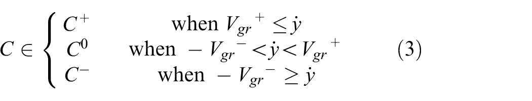
where C+, C−, C0, T0+, and T0− are the border values of parameters describing the physical properties of the model, Vgr+ and Vgr− are the border values of velocity, y is the coordinate variable, and F is the force in the model.
Numerical simulations were carried out for different values of current in the coil of the MRD in the range from 0 to 2 A. The values of parameters obtained from the approximation of experimental results are presented in Table 1.
The values of parameters of the Honker MRD.

MRD: magnetorheological damper.
Vehicle model and control algorithm
In order to investigate the efficacy of a control algorithm, a mathematical model of the vehicle used during road and off-road experiments was built and is shown in Figure 4. The model is proposed in the form of a rigid plate (body of the Honker 2000 vehicle is placed on a rigid frame) based on two axles with the standard suspension, which in Honker consists of leaf springs and hydraulic dampers. In this model, we also included the basic model of a tire which allows taking into account wheels’ dynamics.
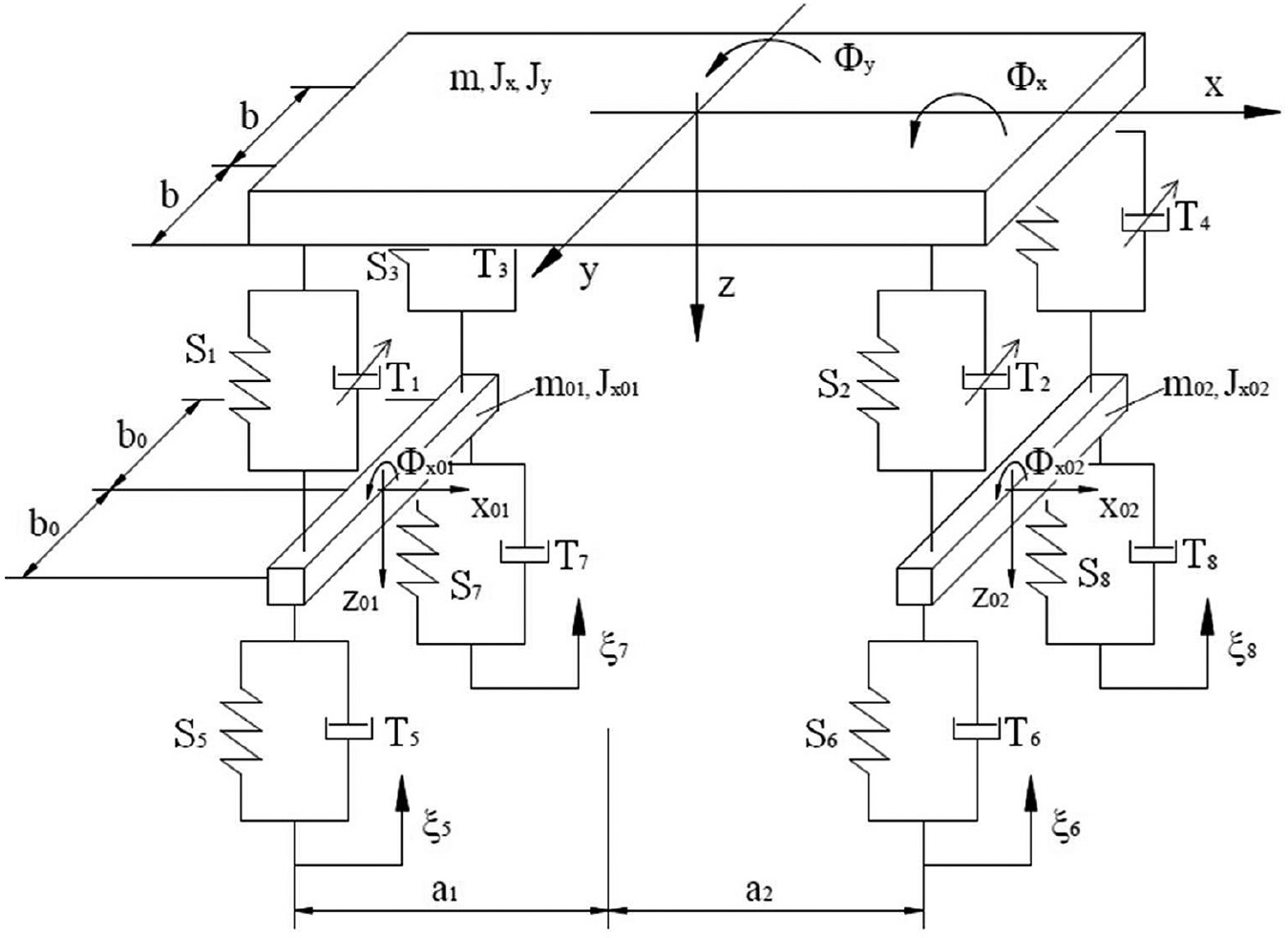
Model of a vehicle used to select optimal damping force in semi-active shock absorbers.
This vehicle model is described by the following parameters:
m—oscillating mass of the body of the vehicle;
Jx, Jy—moments of inertia of the body of vehicle in the longitudinal and transverse axes, respectively;
m01, m02, Jx01, Jx02—masses and moments of inertia of the rear and front axles, respectively;
k1, k2, k3, k4—coefficients describing the stiffness properties of leaf spring;
c1, c2, c3, c4—coefficients describing damping without control;
k5, k6, k7, k8 and c5, c6, c7, c8—coefficients describing the stiffness and damping properties of the wheels, respectively.
Geometry of the model shown in Figure 4 is described by the following parameters:
A kinematic
During field and numerical investigations, the applied external excitation corresponding to road roughness did not cause the situation in which wheel detachments from the road surface could be observed.
The forces acting on the vehicle body and axles are due to leaf springs Si (where the number of wheels i = 1, …, 4), shock absorbers Ti (i = 1, …, 4), and wheels Si and Ti (i = 5, …, 8), respectively.
The vehicle model has been described in the coordinates

where

The model of the vehicle has been described by means of the following set of ordinary differential equations

where the mass matrix
The matrix describing the geometry of the vehicle H is given by

where the vectors Hi (i = 1, …, 8) describe the allowed configuration space to the forces Si and Ti and are defined by the formulas

The vector of kinematic excitations reflecting road roughness is given by the set of the following functions

where
The influence of gravity has been incorporated into the calculations of the initial position of the equilibrium of vehicle suspensions. During the motion of the vehicle, vibrations of its body take place around this initial position. So the impact of the gravity has been omitted in the set of equations (equation (5)).
From the oscillating motion of the vehicle body and its geometry and kinematic excitations, one can determine the suspension deflection Ui (i = 1, …, 4) and the corresponding speed Vi (i = 1, …, 4). In the same way, the wheel deflection Ui (i = 5, …, 8) and the speed Vi (i = 5, …, 8) can be recalculated. The values of Ui (i = 1, …, 8) and Vi (i = 1, …, 8) are calculated by means of


The spring forces Si and the friction forces Ti in the vehicle suspension and wheels are described by means of the following functions of deflections and speeds


where Ti (i = 1, …, 4) in equation (12a) is in the range from


where γ is a function describing the algorithm for designating the signals w(t).
The values of the signals wi(t) are determined on the basis of the following steps. On the basis of the signals from sensors (e.g. accelerometers, displacement sensors) measuring the motion of the vehicle body, it is possible to determine the position and velocity of the vehicle body, allowing for determining the suspension deflection. Subsequently, the forces in the suspension springs supporting the body and the speed of deformation (Vi) in the shock absorber can be calculated. The deformation speed of the damper (Vi) allows, on the basis of the characteristics of the MRD presented in Figure 5 (cf. also Figure 2), to designate the appropriate set of

Area of control and set Ω of the allowed friction forces.
In order to determine Twi and the quality of the control algorithm, we adopt the objective function W of the optimization process characterizing the change in the ratio of the wheels’ force variations. The value of this ratio has been determined by the formula
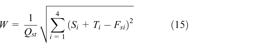
where Qst is the static load caused by overall mass of the vehicle in the initial state, Si is the spring force change during movement of the vehicle in comparison to the initial state, Ti is the friction force in the MRD, and Fsi is the inertial force of the axles and wheels.
The values of the inertial forces Fsi are determined by solving equation (16) describing a submodel of axles and wheels. In this submodel, coordinates are related to points of mounting leaf springs to axles. Also the mass of axles and wheels is divided and lumped in these positions. Consequently, the inertial force Fsi is described by the formula

where the mass matrix of the submodel
The values of acceleration in points of mounting leaf springs to axles are determined by the formula

The matrix describing the geometry of axles and leaf springs Hs is defined by the equation

where the vectors Hsi (i = 1, …, 4) are defined by the formula

Finally, the value of the friction force in the MRD is chosen to minimize the value of the functional W. This condition can be satisfied by the force vector which should be realized by MRDs

which determines solution to the following, simplified to the argument of the square root of the functional W, optimization problem

The solution of the above problem minimizes the simplified functional in equation (21) allowing for the determination of the vector forces Tw of MRDs in the set of allowed solutions

Numerical simulation—fluctuation of the calculated currents in the MRD for kinematic excitation with 0.05 m amplitude and 2.25 Hz frequency, with applied algorithm of control.
One of the most important steps in the presented algorithm of control is the damper characteristic and the possibility of setting adequately a wide range of minimal and maximal friction forces which can affect the solution of the optimization process. It is also apparent that the characteristics of different types of dampers can be used, for example, the characteristics of electrorheological dampers or hydraulic dampers with proportional valves. From this point of view, the presented algorithm is to some extent universal.
Numerical simulation of the off-road vehicle
Numerical investigations of the control algorithm were carried out using the simplified model of the vehicle developed in the MATLAB/Simulink software. During computer simulations, the following values of parameters of the vehicle model were employed: weight of the vehicle m = 2350 kg, moments of inertia Jx = 2054 kg m2 and Jy = 11,897 kg m2, spring stiffness values k1 = k2 = k3 = k4 = 52,000 N/m, track of wheel length a1 = a2 = 1.45 and wheel base b = 0.515 m, m01 = m02 = 100 kg, moment of inertia Jx01 = Jx02 = 64 kg m2, b0 = 0.815 m, and k5 = k6 = k7 = k8 = 284,000 N/m.
In the numerical simulations, we compared vehicles with the passive suspension (original suspension) and with semi-active suspension with MRD. For constant damping (which corresponds to passive original dampers), the values of the dimensionless damping coefficient of γc = 0.3 (damping coefficients c1 = c2 = c3 = c4 = 6645 N s/m) and the damping coefficients c5 = c6 = c7 = c8 = 240 N s/m were used. In the case in which the vehicle with MRD was analyzed, this coefficient was in the range from γmin = 0.05 to γmax = 3 (cmin = 1107 N s/m, cmax = 66,450 N s/m) for the extension and about five times lower in range for the compression. In this case, the values of γmin correspond to the situation in which the MRD is supplied with the current of 0 A, while the γmax values correspond to the situation in which the MRD is supplied with the current of 2 A. The values of friction forces were calculated using the above algorithm with the criterion of minimizing values of vertical wheel force changes (cf. equation (21)). After determining the values of friction forces in dampers, the corresponding currents in dampers can also be calculated on the basis of the damper characteristic (cf. Figures 3 and 5).
In Figures 6 and 7, the results for excitation with amplitude A = 0.05 m and frequency 2.25 Hz, as in the previous case, are presented. Figure 6 shows the value of the calculated currents in the front suspension of the MRDs. The fluctuations of the currents are different than in the previous case, caused by a different amplitude and car body dynamics. Figure 7 presents the comparison of values of the coefficient W for vehicles with passive (called as “without control”) and those with semi-active suspension (called as “with control”). As in the previous case, smaller variations in the value of vertical wheel force can be observed.
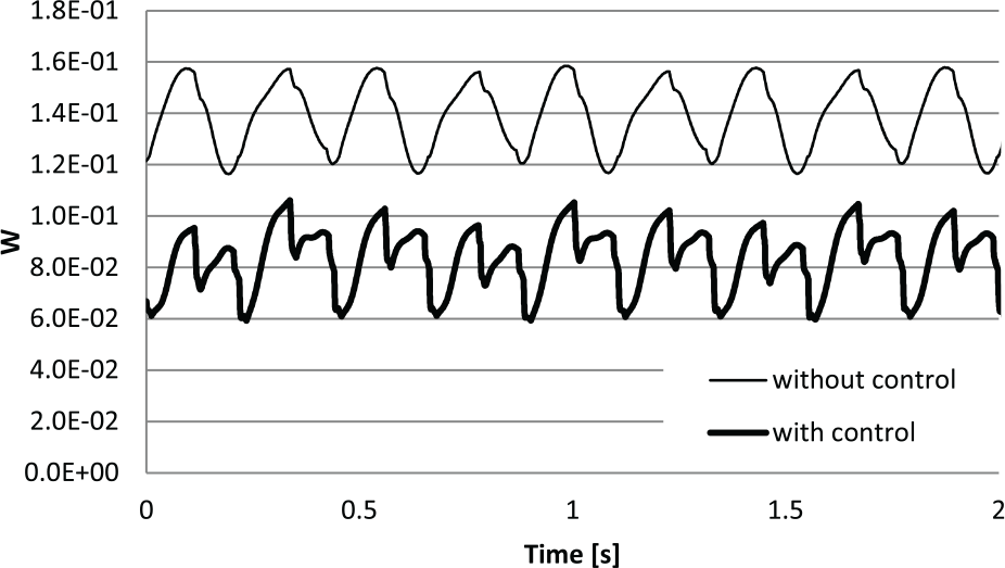
Numerical simulations—comparison of the coefficient W in the case of vehicles with (with control) and without (without control) applied MRD for kinematic excitation with 0.05 m amplitude and 2.25 Hz frequency.
The evaluation of the coefficient W shows that in the case when the control algorithm was used the average value of the coefficient W was reduced in the range from 1.39 × 10⁻¹ (stock shock absorbers) to 8.45 × 10⁻² (MRDs with active control) and during peaks from 1.58 × 10⁻¹ to 1.02 × 10⁻¹. Consequently, our numerical test results show an improvement in the value of the coefficient W by 39% taking into account the average value.
Traction field tests
In order to assess the effectiveness of the control algorithm and that of the MRD, we carried out numerous laboratory and field tests. The field tests consisted of road and off-road tests and used an off-road vehicle Honker 2000 (Figure 8).
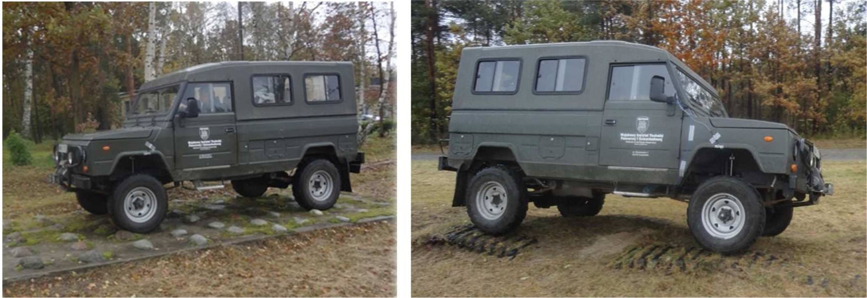
The off-road vehicle Honker 2000 employed in our field tests.
Only the front suspension of the vehicle was equipped with MRDs controlled by the electronic system with the algorithm of friction force control and current calculation. The rear suspension remained unchanged from the original factory configuration.
The measurement system consisted of the sensors for the measurements of the vehicle velocity, suspension deflection, rotation of the steering wheel, and horizontal and vertical accelerations of the vehicle body. The measurement of the front suspension deflection of the wheels against the chassis was important for the overall performance of the damping force and employed the control algorithms described earlier. Based on its value, the control current in each damper was calculated and generated by the additional supply unit. Currents in the MRD were computed in accordance with the previously described algorithm and included in the algorithm the experimental (idealized) characteristics of the MRD (cf. Figures 3 and 5). All the measured and controlled signals were recorded during the test by means of a computer-based acquisition system.
Traction tests were conducted on several special research terrain road sections and normal road for original and modified suspension (with MRDs). During the road tests, the vehicle maintained a constant velocity in the 60–90 km/h range, while during the off-road tests it was maintained in the 15–30 km/h range.
The off-road result examples for the vehicle with a velocity of about 15 km/h and for the suspension with MRD and road section shown in Figure 9 (left) are presented in Figures 9–11.

Traction test results on the off-road section no. 1—the deflection of the front right wheel suspension with MRD.
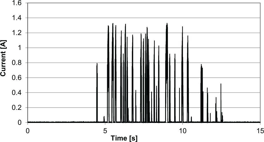
Traction test results on the off-road section no. 1—the values of currents in the coil in MRD in the front right wheel suspension.

Traction test results—the fluctuation of the coefficient W for the original suspension system.
Figure 9 shows the deflection of the front right wheel suspension. In Figure 10, the values of currents in the front right MRD calculated by the proposed algorithm and generated by the power supply are presented. It is clearly visible how the values of currents correspond to terrain roughness and deflections of the suspension.
In Figure 11, the evaluation of the coefficient W for the vehicle during the same off-road test on section no. 1 with stock suspension and with MRD in the front suspension is presented. The results show that the average value of the coefficient W was reduced in the range from 0.068 (stock shock absorbers) to 0.0533 (MRDs with semi-active control) and during peaks from 0.45 to 0.22. So, with respect to the average values of the coefficient W, 21.5% reduction in changes of vertical forces was recorded.
The off-road test results for the vehicle with a velocity of about 15 km/h on the off-road section no. 2 (cf. Figure 8, right image) and for suspension with MRD are presented in Figures 12–14. The traction tests were also repeated on the same section of a special research terrain road for the vehicle with suspension containing the original hydraulic dampers.

Traction test results on the off-road section no. 2—the deflection of the front right and left wheel suspension with MRD.

Traction test results on the off-road section no. 2—the values of currents in the coil in MRD in the front right and left wheel suspension.

Traction test results—the fluctuation of the coefficient W for the original and modified suspension systems.
Figure 12 shows the deflection of the front right and left wheel suspension. In Figure 13, the values of currents in the front right and left MRD calculated by the proposed algorithm and generated by the power supply are presented. It is clearly visible how the values of the currents correspond to terrain roughness and deflections of the suspension.
In Figure 14, we present a comparison of the fluctuation of the coefficient W (cf. equation (15)) for the original suspension and the suspension with MRD. It can be observed that during the period from the fifth to tenth second the values of the coefficient W are smaller for the suspension with MRD by about 40% in comparison to the original suspension. The results also indicate that the average value of the coefficient W at the time of the test for the original suspension is WO = 0.0554 and for the MRD suspension WMR = 0.0469, which generally suggests that in the case of the suspension with MRDs smaller changes of vertical forces can be observed. So the described control algorithm has been quite effective during the investigated off-road tests.
Conclusion
We presented a control algorithm to adjust properly the properties of the MRD in order to minimize vertical wheel force variations in the suspension of an off-road vehicle. The presented experimental results were carried out using the Honker 2000 off-road vehicle equipped with MRD in the front suspension. The results of the vehicle traction tests demonstrated that it is possible to reduce variations of wheel forces using MRD.
In order to measure the effectiveness of control, we introduced a coefficient, the average value of which in the numerical and experimental investigations was lowered up to 21% (in peaks above 50%). Obtaining a lower value was possible by means of MRD (instead the original one) along with the control algorithm.
Also, it should be noted that the presented limited effectiveness of the control algorithm can probably be further improved in the future by mounting MRD in the rear suspension as well. Also, some results have shown that it can be necessary to improve MRD damping characteristics (wider control area of minimal and maximal damping forces) by redesigning dampers. The results of the presented experimental research show that while the maximum current values of 2 A are rarely achieved, on many segments the value of current amounts to 0 A. It means, therefore, that an MRD should, in many cases, function with the minimal damping force. In such a case, it would be better if the MR damper control field were greater and obtaining even smaller damping force values were possible. However, due to the safety considerations, we have adopted a compromising solution, so that in case of power supply loss, a relatively significant damping force could be applied.
It should also be mentioned that further investigations are possible and should be conducted especially in the field of the problems not discussed here like time delay, stability of control algorithm, identification of suspension failure, and the use of the control algorithm with different criteria of optimization (e.g. comfort).
Footnotes
Handling Editor: Seung-Bok Choi
Declaration of conflicting interests
The author(s) declared no potential conflicts of interest with respect to the research, authorship, and/or publication of this article.
Funding
The author(s) disclosed receipt of the following financial support for the research, authorship, and/or publication of this article: This project was funded by the Polish National Centre for Research and Development allocated on the basis of the decision number PBS3/B6/34/2015.