
Abstract
The capsule vehicle is a new transportation system that travels in a sub-vacuum tunnel at a speed of about 1000 km/h, and adopts the electrodynamic suspension type levitation system. Accordingly, although it differs according to the driving speed, the vibration of capsule vehicle is expected to be greater than that of the wheel/rail type high-speed rail vehicles. Therefore, a method of applying a semi-active control technique using an MR damper as a secondary suspension of a capsule vehicle to improve passenger comfort is being studied. When performing semi-active control using an MR damper, the most important thing is to determine the current for the MR damper. However, it is difficult to determine the appropriate current for the MR damper because of the hysteretic characteristics of the MR damper. In this study, a practical model named the Bi-exponential model is presented for the application of semi-active control using MR dampers on a capsule vehicle. This Bi-exponential model well reflects the hysteretic characteristics of the MR damper, which makes it easy to obtain the inverse model for determining the current supplied to the MR damper. The semi-active control performance of the Bi-exponential model was evaluated by simulation and a HILS experiment, taking into account the vertical motion of a 1/4-car capsule vehicle. Also, the Bi-exponential model has been validated against the performance of the most commonly used Bouc-Wen model. As a result, the Bi-exponential model showed better hysteretic characteristics of MR dampers compared to the Bouc-Wen model. Furthermore, despite the simpler model compared to the Bouc-Wen model, the semi-active control performance of the Bi-exponential model was found to be better.
Introduction
A magnetorheological (MR) damper is a variable damper with a damping force that changes with the applied current and is effectively used for semi-active control. Passive dampers 1 cannot respond to external load changes, while active dampers,2,3 developed to make up for such a deficiency, are expensive and limited in terms of development and application due to their excessive energy consumption and complex structure. The MR damper used for semi-active control4,5 combines active and passive devices and is popular for its superior performance as it reacts to load change better than passive devices while being more energy-efficient and cost-effective than active devices. There is a growing trend of applying MR dampers to the secondary suspension systems of transport vehicles, such as passenger and railway vehicles, to improve passenger ride quality. However, despite the advantages of a faster response and lower power requirements than other devices in the same class, semi-active control using an MR damper is more difficult to design due to the damper’s hysteretic characteristics. Therefore, applying an MR damper to the secondary suspension systems of transport vehicles requires a good mathematical model of the MR damper’s physical characteristics and the control system that uses it.
The mathematical models that represent the physical characteristics of the MR damper include the Bingham model,6,7 polynomial model,8,9 Bouc-Wen model, 10 Spencer et al. model, 11 nonlinear hysteretic biviscous model, 12 Sigmoid model, 13 and the hyperbolic tangent hysteresis model.14,15 Although the Bingham model allows a fairly simple mathematical expression, it does not implement the MR damper’s hysteretic characteristics and thus has a poor control performance. The polynomial model supplements the weakness of the Bingham model by modeling the velocity-force hysteresis characteristics. However, the model shows a performance deterioration if the hysteresis curve is asymmetric or irregular. On the other hand, the Bouc-Wen and Spencer models show better performance than the others, but obtaining the model parameters is complicated because they include complex mathematical formulas containing many parameters. Moreover, even after obtaining the parameters, it is very difficult to provide an inverse model (a mathematical model for the current to derive the MR damper force needed for semi-active control) for field application. Therefore, the field application of these models assumes that the key parameters of the mathematical models are linear functions of the current. The nonlinear hysteretic bi-viscous model divides the hysteresis of the MR damper velocity-force graph into six sections and obtains the MR damper force at each section. Its disadvantage is that it selects some parameter values arbitrarily. The hyperbolic tangent hysteresis model expresses the MR damper’s hysteresis as a hyperbolic tangent function because of its shape. However, it is difficult to identify the inverse model due to the complex mathematical equations involved.
These mathematical models have been developed to express the nonlinear characteristics of the MR damper. Some studies16–18 have attempted to combine some of these models to highlight the advantages and mitigate the disadvantages of each. Recently, Yuan et al. 16 suggested a model combined with the exponential function and the hyperbolic tangent hysteresis model, Cheng et al. 17 studied a model using the Tanh model based on the hyperbolic tangent hysteresis model, and Lu et al. 18 presented a model applying the sigmoid model. Nevertheless, the mathematical formulas of these recently proposed models still contain many parameters, it is very difficult to obtain the parameter values. In this study, a simple and practical model is proposed by referring to the hyperbolic tangent hysteresis model as a reference in order to fully reflect the MR damper’s hysteresis characteristics with less mathematical complication. It also discusses the suggested model’s semi-active control performance.
Mathematical and inverse models of the MR damper
Figure 1 shows the semi-active control system process using an MR damper. The most critical factor of the control using an MR damper is to determine the current supplied to the MR damper. Since an MR damper’s damping force depends on the displacement, speed, and current of the MR damper, the system must supply a suitable current for the speed and displacement to generate a control force appropriate for the MR damper. Therefore, the inverse model of the MR damper is crucial to derive the necessary current, but the process is very difficult because of the nonlinear hysteresis characteristics of the MR damper. In this regard, correctly reflecting the MR damper’s hysteresis characteristics is the key factor to implement the semi-active control system for improved ride comfort.
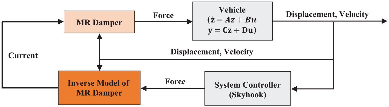
Block diagram of the semi-active control system.
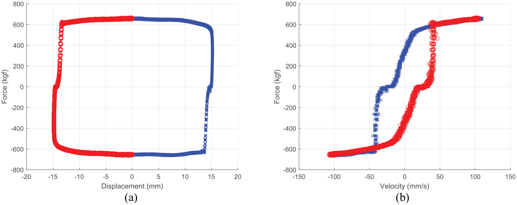
Hyperloop 19 is a new transportation system proposed by Elon Musk of SpaceX. It is an ultra-high-speed transportation system that involves a vehicle running at 1000 km/h, or faster, through an almost vacuum tube. Engineers designing capsule vehicles for the Hyperloop system are considering the application of MR dampers for the secondary suspension system of capsule vehicles like automobiles and railway vehicles. The force-displacement and force-velocity graphs in Figure 2 show the MR damper’s characteristics considered for the secondary suspension system of the capsule vehicle in this study. The semi-active control system using the MR damper is designed based on these characteristics’ graphs.
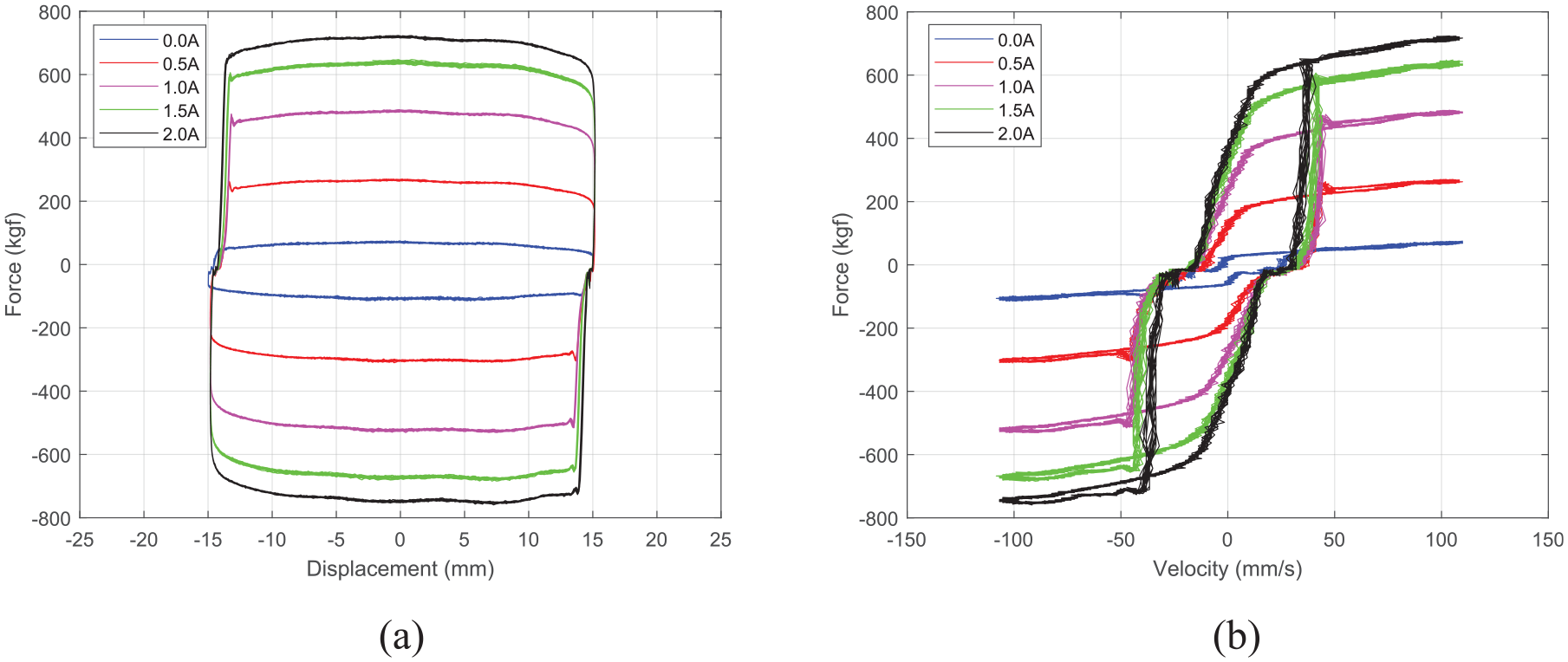
Performance of MR damper for capsule vehicle: (a) graph of displacement-force and (b) graph of velocity-force.
As mentioned above, this study proposes a new, simple, and practical model instead of a complex mathematical one. It verifies the proposed model’s feasibility by deriving the new MR damper model using the data in Figure 2 and comparing it to the Bouc-Wen model.
Bouc-Wen model
Mathematical modeling by the Bouc-Wen model
The Bouc-Wen model is the most widely used for modeling nonlinear systems’ hysteresis characteristics. The model expressed in differential equations was first proposed by Robert Bouc
10
and supplemented by Yi-Kwei Wen
20
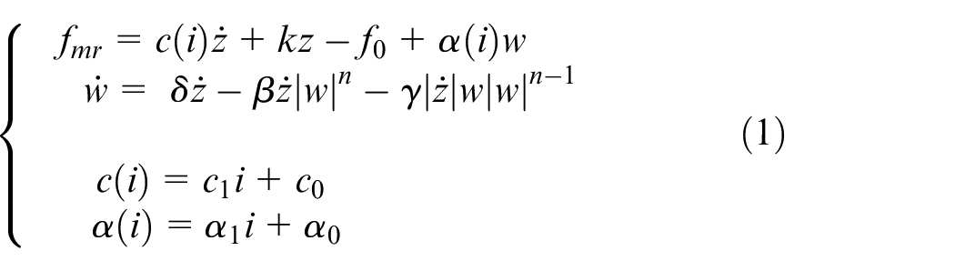
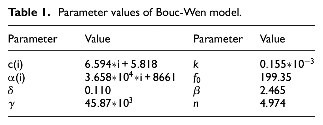
and other scholars.11,21,22 Although the Bouc-Wen model is configured with complex mathematical equations containing many parameters, this study adopted it as the reference for comparison since it can appropriately implement the hysteresis curve with the selection of the appropriate parameter values. The following equation (1) is the mathematical expression of the Bouc-Wen model for the MR damper shown in Figure 2. In this equation,
Parameter values of Bouc-Wen model.
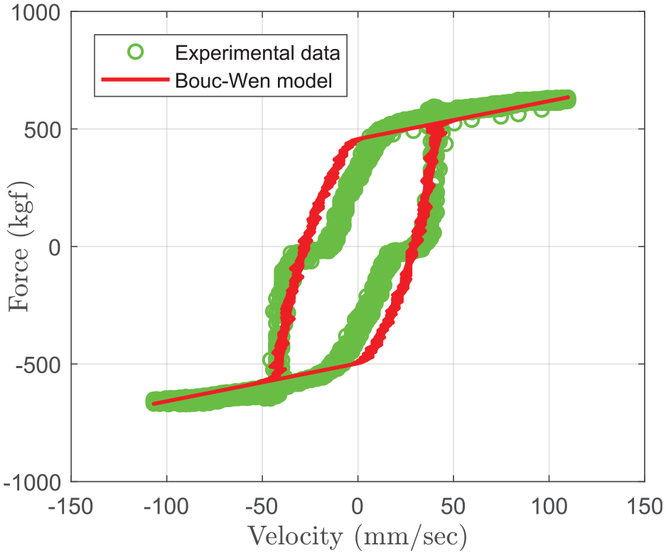
Comparison of experimental data and Bouc-Wen model.
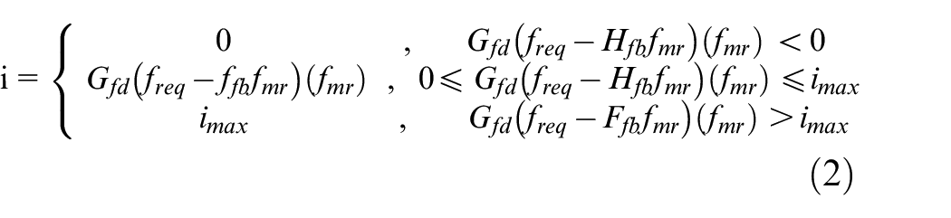
Inverse model by the CSDC algorithm
An inverse model using the continuous state damper controller (CSDC) algorithm
37
has been constructed to apply the Bouc-Wen model to the semi-active control. The input current
Bi-exponential model
The Bi-exponential model proposed by this study is constructed with reference to the hyperbolic tangent hysteresis model.14,15,38 The hyperbolic tangent hysteresis model is based on the concept that the hysteresis can be mathematically expressed as a hyperbolic tangent function and the viscosity and stiffness as linear functions. The MR damper force in this model can be expressed by equation (3).
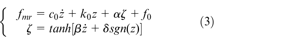
Since even the hyperbolic tangent hysteresis model was developed to have a relatively small number of reliable parameters, it is still configured with complex mathematical equations and more difficult to derive an inverse mathematical model the same as the Bouc-Wen model. Therefore, this study uses the Bi-exponential model using two exponential functions instead of a hyperbolic tangent function to reduce complexity and derive the practical inverse mathematical model more easily than the hyperbolic tangent hysteresis model.
MR damper characteristics and mathematical model
The MR damper’s force-displacement and force-velocity characteristics are classified by the displacement sign. Figure 4 shows the characteristics when a 1.5 A current is applied to an MR damper. The figure indicates that the force follows the upper curve of the force-velocity hysteresis curve if the displacement is positive and the lower curve if the displacement is negative. Therefore, this study separates the upper and lower curves according to the sign of displacement for the Bi-exponential model and reviews the semi-active control system’s performance using a hardware in the loop simulation (HILS) by a separate curve fitting.
Characteristics of MR damper according to the sign of displacement: (a) force-displacement relationship and (b) force-velocity relationship.
Firstly, the velocity-force hysteresis curve in Figure 4(b) is modeled in the following equation using an exponential function. Separate curve fittings were performed using this model according to the sign of displacement.
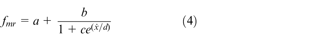
Here,
Curve-fit results with the Bi-exponential function
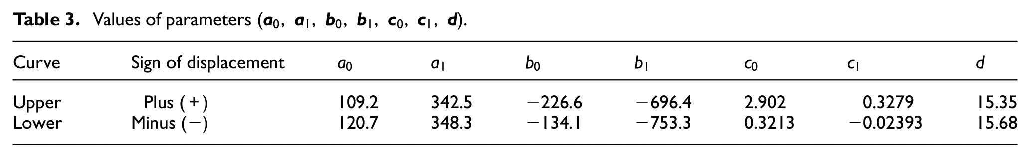
The curve-fits using equation (4) are separately performed on the upper and lower parts of the force-displacement curve with the MR damper obtained from the experimental data for each current value. Figure 5 shows the result. As mentioned above, the most important factor of a semi-active control system using an MR damper is to determine the current supplied to the MR damper. Therefore, it is necessary to derive the inverse equation to determine the current to generate the MR damper’s damping force calculated from equation (4). As shown in Figure 5, the parameters a, b, c, and d are the functions of the current derived from equation (4). To simplify the inverse model, a, b, and c are approximated with the linear functions of the current, and d is approximated to a constant. For the d value, the average of the parameter values according to the current shown in Figure 5(d) is calculated. As a result, the d value is calculated to be 15.35 in the upper curve and 15.68 in the lower curve. The parameters a, b, and c according to the current for MR damper are then obtained using the d value and are shown in Figure 6. The graphs indicate that a linear function of current can approximate a, b, and c each. Table 2 shows the result of curve fitting to the linear functions.
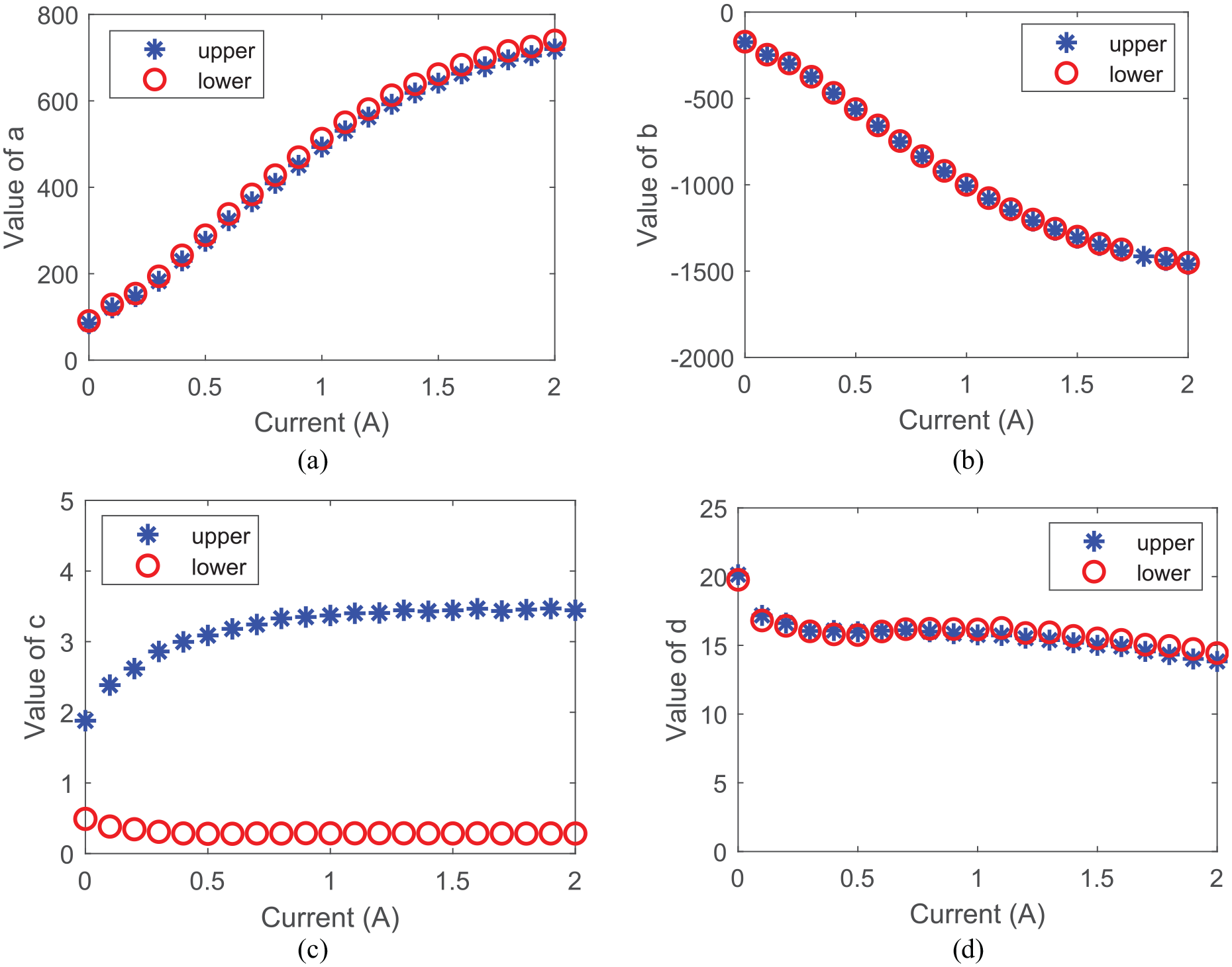
The tendency of parameter values (a, b, c, d) according to current: (a) parameter a, (b) parameter b, (c) parameter c, and (d) parameter d.
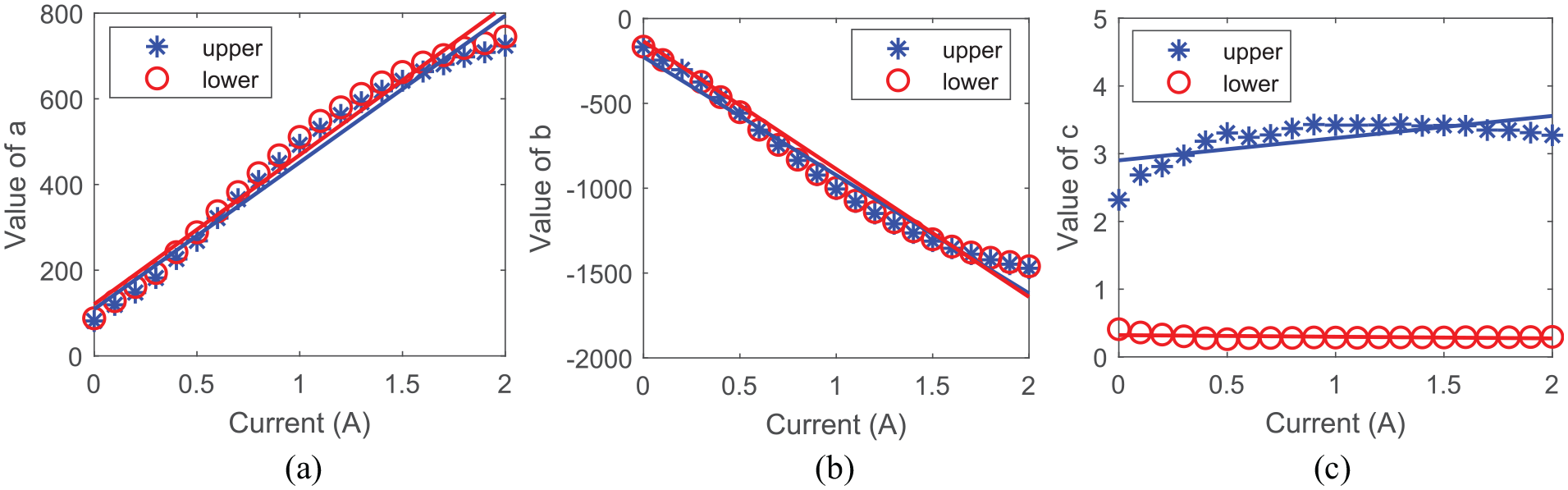
The tendency of parameter values (a, b, c) according to current (fixed value d): (a) parameter a, (b) parameter b, and (c) parameter c.
Linear functions of parameters (a, b, c).
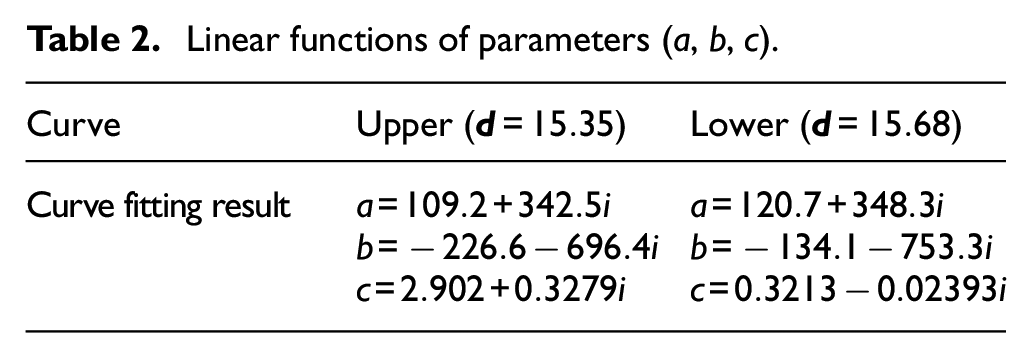
In Table 2, i means the current applied to the MR damper.
The derived mathematical model was compared with the force-velocity graph of the actual MR damper to check its accuracy. Figure 7 shows the upper and lower curves for 1.5 A using equation (4) and Table 2 as experimental data. It confirms that the derived mathematical model approximates the experimental data well. The RMSE between the Bi-exponential model and the experimental data is 61.8. This value is significantly smaller than the RMSE of the Bouc-Wen model, 695.3, and this shows that the Bi-exponential model has a higher accuracy than the Bouc-Wen model.
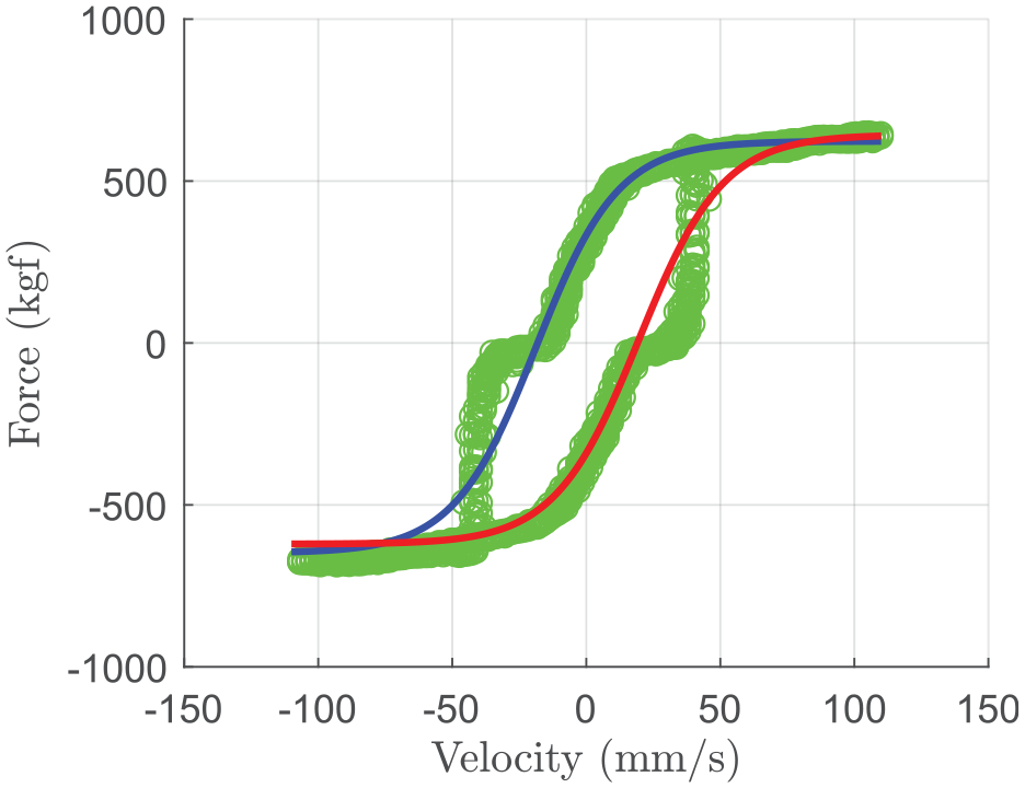
Comparison of experimental data and Bi-exponential model.
Inverse model
The input current to generate the force required by the MR damper can be obtained using Table 2 and equation (4) as follows. The relationship between current and damping force by MR damper is expressed in equation (5).
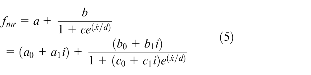
In equation (5), a, b, and c have different values depending on the sign of the displacement. As summarized in Table 2, when the displacement is positive, the value of the upper curve is selected, and when the displacement is negative, the value of the lower curve is selected. a, b, and c are arranged as the sum of a constant term and a term that is linearly proportional to the current, respectively.
The equation can be rearranged for current


Values of parameters
Finally, the current
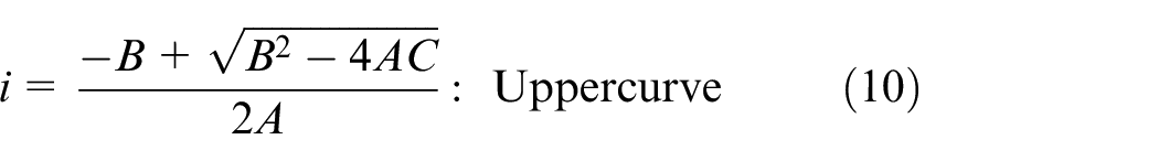
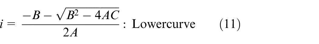
Equations (10) and (11) are validated only under the condition of
Performance of the Bi-exponential model by simulation
Matlab/Simulink simulation system using the 1/4-car model of capsule vehicle
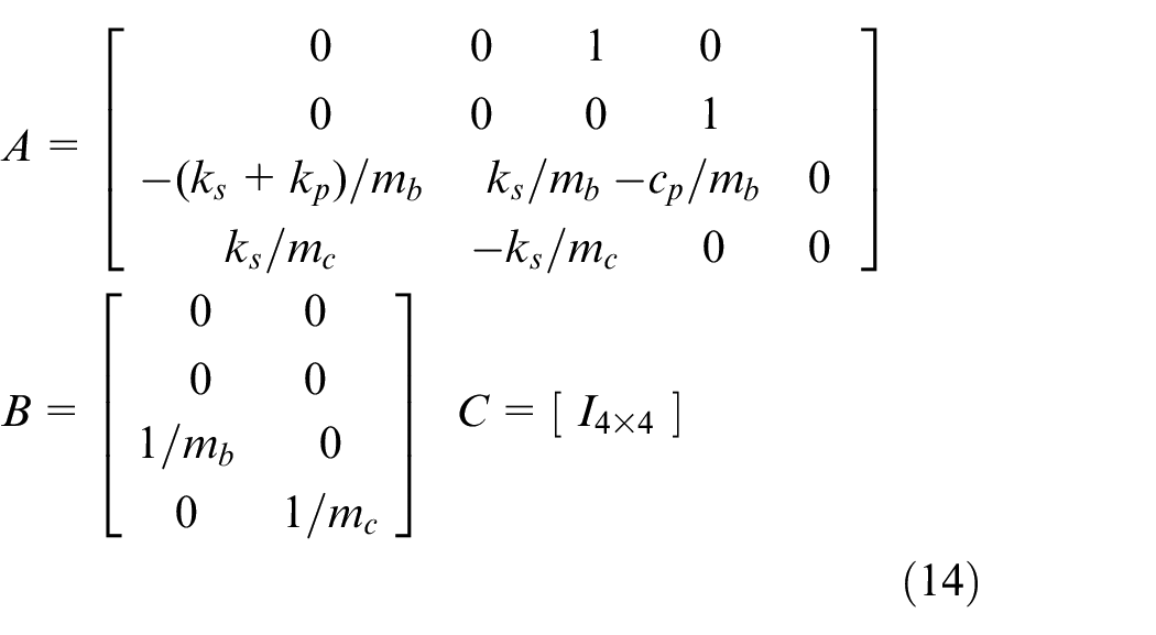
A simulation using the Matlab/Simulink software was performed to check the semi-active control system performance using the Bi-exponential model of the MR damper. The mathematical model used in this paper consists of two degrees of freedom, considering only the vertical displacement of the 1/4-car model of capsule vehicle, as shown in Figure 8. In Figure 8,
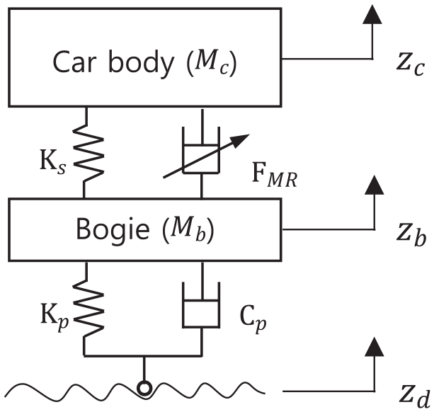
Dynamic model of 1/4-car model of capsule vehicle.
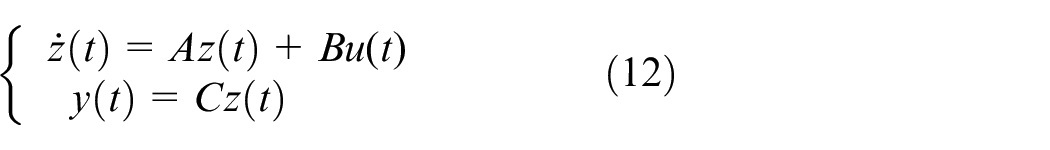
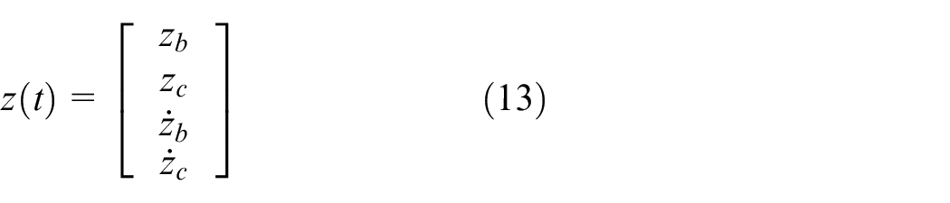
Equation (12) is the state-space equation of the model’s equation of motion shown in Figure 8. The state vector
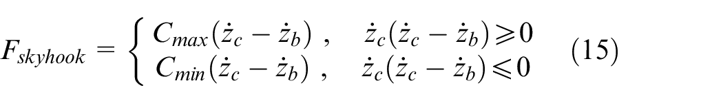
The Skyhook control algorithm,
39
expressed by equation (15), was used to derive the force generated by the secondary suspension system through the MR damper. As shown in equation (15), the Skyhook control algorithm calculates the required force by multiplying the relative velocity of the car body and bogie by the maximum value (
The calculated force is applied to the system (vehicle) through the Bouc-Wen and Bi-exponential models with the Simulink software, as shown in Figure 9.
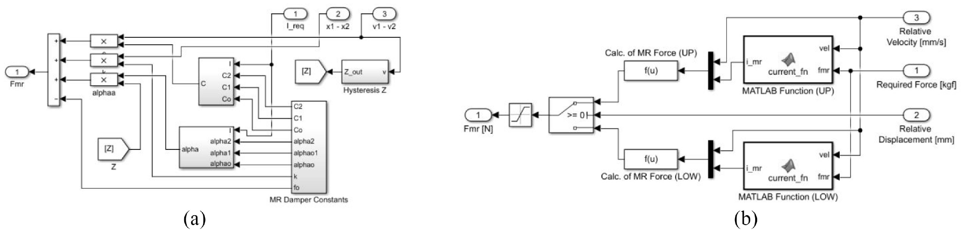
MR damper module for semi-active control by MATLAB/Simulink software: (a) Bouc-Wen model and (b) Bi-exponential model.
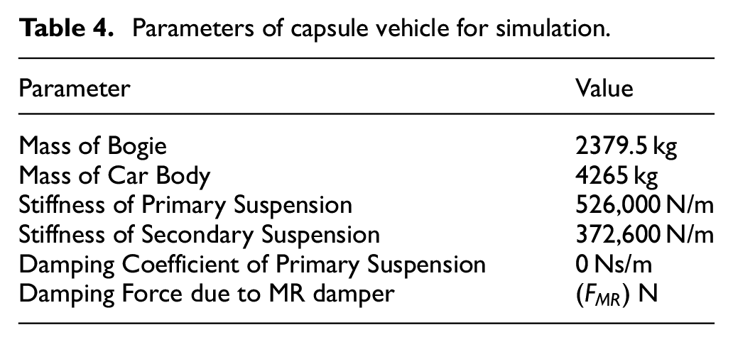
Table 4 shows the capsule vehicle parameter values. Unlike a conventional railway system, the capsule vehicle runs on a magnetic levitation system with electrodynamic suspension (EDS) by non-contact superconducting electromagnets. The sidewall EDS magnetic levitation system applied to the capsule vehicle generates levitation and guidance forces by the repulsive force between the induced magnetic fields generated when the superconducting magnet mounted on the bogie passes through the levitation coil of the guideway.40,41 At the same time, the levitation and guiding forces are considered as primary vertical and horizontal suspensions, respectively, of the capsule vehicle. Therefore, the vertical spring stiffness of the capsule vehicle’s primary suspension reflects the value at the running speed of 810 km/h, excluding the nonlinear characteristics in the levitation stiffness. It is assumed that there is no damping.
Parameters of capsule vehicle for simulation.
Analysis of simulation results
Figure 10 shows the vertical displacement of the bogie and car body in the simulated time domain when a capsule vehicle runs on an irregular guideway with amplitude of about 8 mm. All cases of applying the passive suspension system, the Bouc-Wen model, and the Bi-exponential model confirm that the bogie includes more high-frequency components than the car body. This is because, in the two-degrees of freedom model shown in Figure 8, the first mode mainly appears in the car body while the second mode, showing a higher frequency than the first mode, is strongly manifested in the bogie. Displacement is generally greater with the passive suspension system, followed by the Bouc-Wen model. The Bi-exponential model shows a significantly small value.
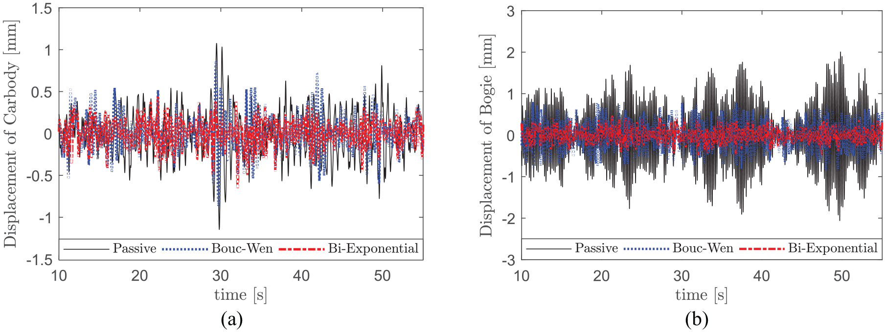
Simulation results for capsule vehicle in the time domain: (a) displacement of car body and (b) displacement of bogie.
As shown in Figure 11, the frequency analysis result indicates the significantly sized peak of the car body and bogie displacement at 1.3–2.6 Hz, which corresponds to the first mode’s natural frequency. Only the passive suspension system and Bouc-Wen model cases show the peak value at 5.2–5.6 Hz, which corresponds to the second mode’s natural frequency. The simulation result shows that the Bi-exponential model can effectively reduce the second mode.
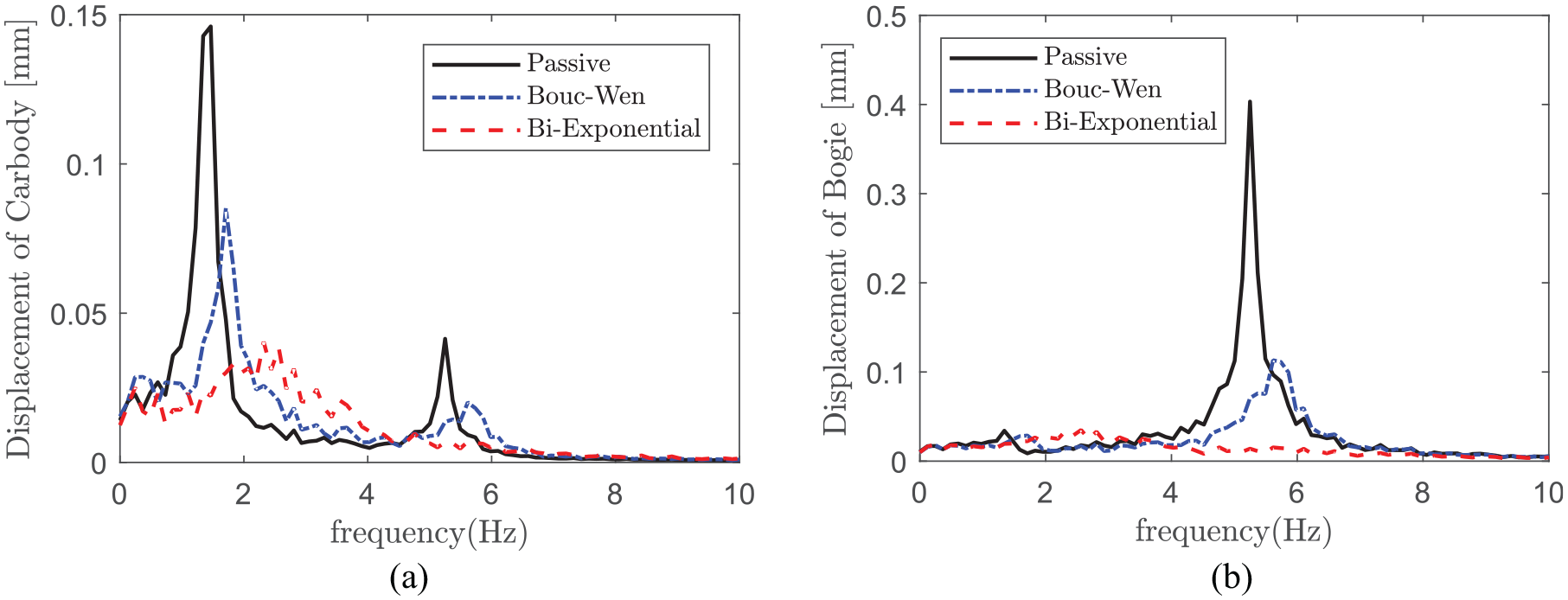
Simulation results for capsule vehicle in frequency domain: (a) displacement of car body and (b) displacement of bogie.
In order to compare the vibration reduction performance of the Bouc-Wen model and the Bi-exponential model, the vibration reduction effect as shown in the equation (16) was used.
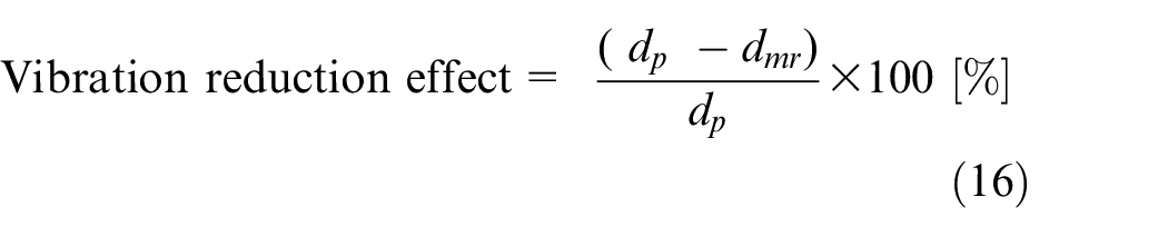
Here,
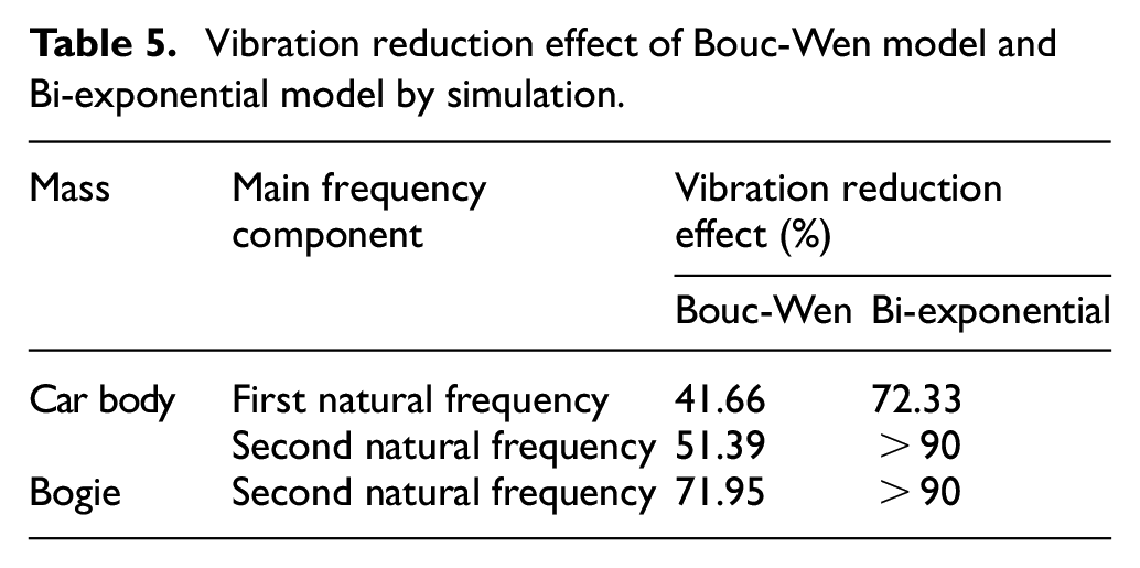
Table 5 summarizes the peak values of the first and second natural frequencies calculated with equation (16) to compare quantitatively the performances of the Bouc-Wen and bi-exponential models of the MR damper to be applied to the secondary suspension system of the capsule vehicle. For the first natural frequency, the main component of car body vibration, the Bi-exponential model shows a 72.33% reduction in car body vibration, confirming that it is superior to the Bouc-Wen model, which shows a reduction of 41.66%. The Bi-exponential model also shows a far greater reduction than the Bouc-Wen model in the comparison of peak values at the second natural frequency, the main component of the bogie vibration. In conclusion, the simulation results prove that the Bi-exponential model can reduce the bogie and car body vibrations much more effectively than the Bouc-Wen model.
Vibration reduction effect of Bouc-Wen model and Bi-exponential model by simulation.
Performance of Bi-exponential model by HILS test
Design of HILS test system
The hardware in the loop simulation (HILS) test was conducted using the same dynamic model under the same condition as the simulation with Matlab/Simulink. Since the dynamic model consists of the two-degrees of freedom model in the vertical direction at a one-fourth model size, the testing system is configured of a load cell, an MR damper with characteristics shown in Figure 2, dSpace, and control computer, as shown in Figure 12. The configuration considers only the MR damper mounted on the secondary suspension system between the car body and bogie. The HILS drive motor generates a relative displacement between the car body and bogie calculated by the controller, and the load cell measures the MR damper’s damping force. In other words, this testing system implements the dynamics of the Matlab/Simulink software model used in the simulation through the ControlDesk system of dSpace. As mentioned above, the most important factor is the inverse model that calculates the current value required for the control force of the MR damper. Figure 13 shows the Simulink software implementation of each inverse model derived during the development of the Bouc-Wen and Bi-exponential models. H_sky and G_Sky in (a) are the
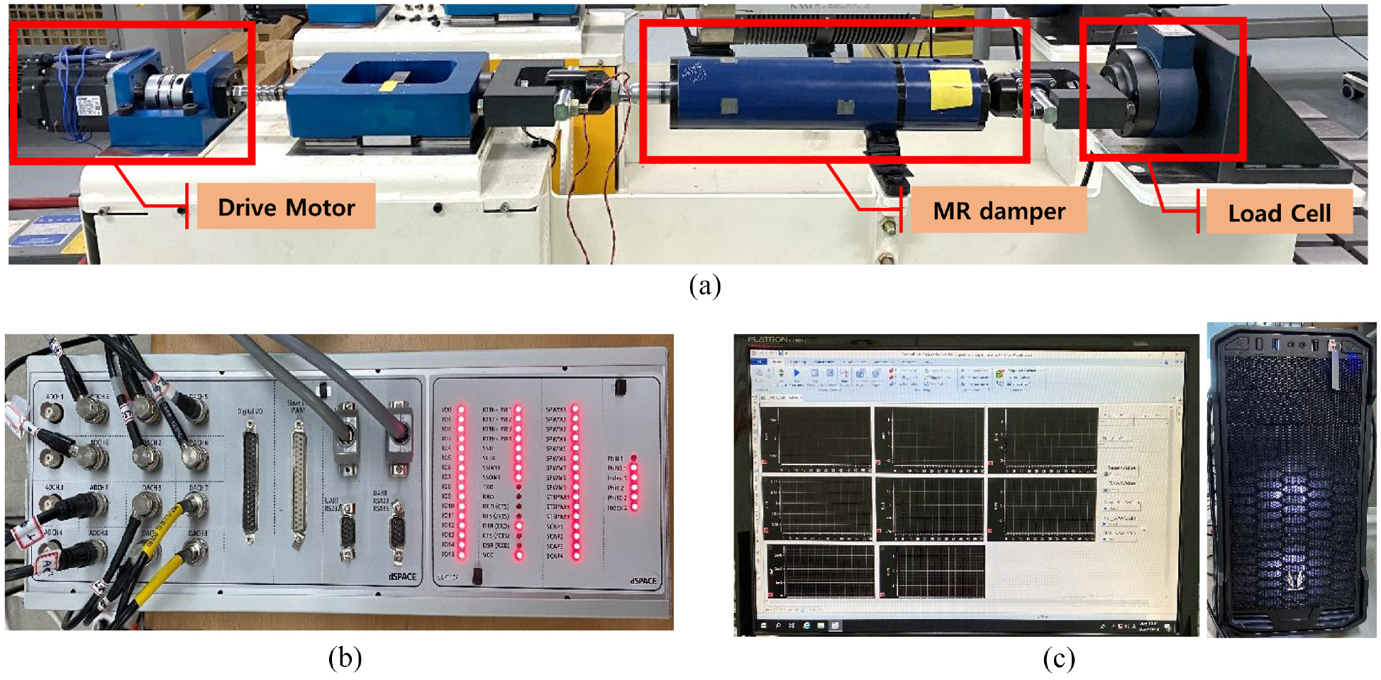
Experimental setup for HILS using MR damper: (a) MR damper system (hardware), (b) dSPACE, and (c) computer for control.
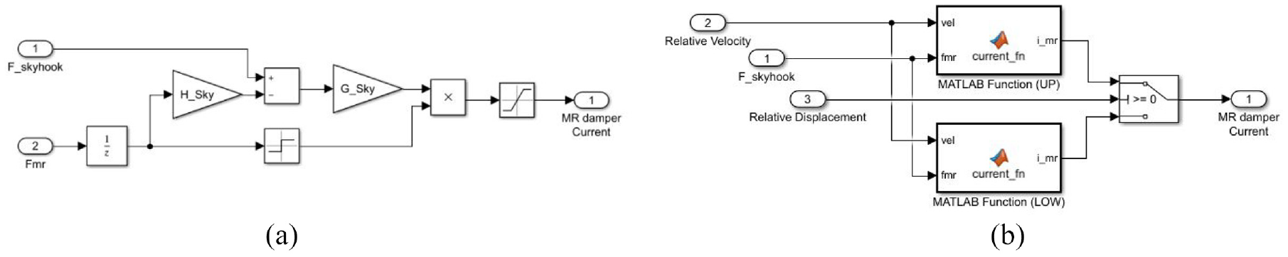
Inverse MR damper module for semi-active control by Simulink software: (a) Bouc-Wen model and (b) Bi-exponential model.
Analysis of HILS test results
Figure 14 shows the displacements of the car body and bogie within the time domain of the HILS test. Although all three models show similar tendencies, the displacement of the passive suspension system and the Bouc-Wen model application are similar while that of the Bi-exponential model application is lower. The results are somewhat different from the simulation results in which the displacement is significantly lower in the order of the passive suspension system, the Bouc-Wen model application and the dual exponential model application.
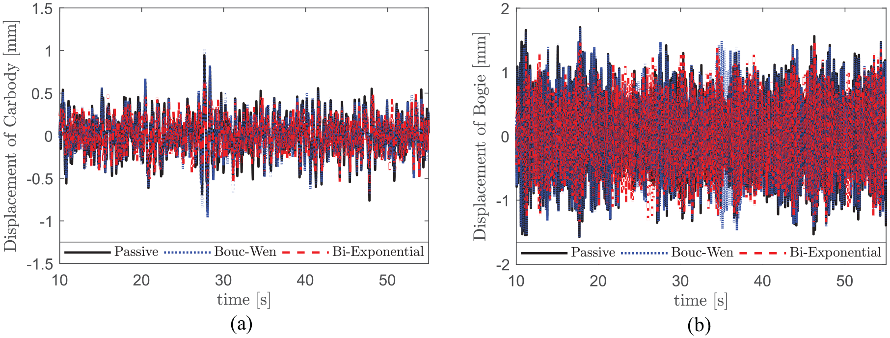
HILS test results of time domain of the capsule vehicle: (a) displacement of car body and (b) displacement of bogie.
Figure 15 shows the results of the frequency analysis of the time-domain signals shown in Figure 14. The results indicate that the first natural frequency (1.3–1.5 Hz) and the second natural frequency (5.9–6.1 Hz) are mostly manifested in the car body’s displacement, while the peak frequency component of the second natural frequency mainly emerges in displacement of the bogie. They show a similar tendency as the simulation results except for the smaller first mode and larger second mode than the car body simulation. Moreover, the second mode’s natural frequency is higher than the simulation. The comparison of peak values at the natural frequency for each mode shows that in the first mode, the passive suspension system is the highest while the Bi-exponential model application is the lowest. In the second mode, which is the main component of bogie vibration, the Bi-exponential model application is slightly lower than the Bouc-Wen model application.
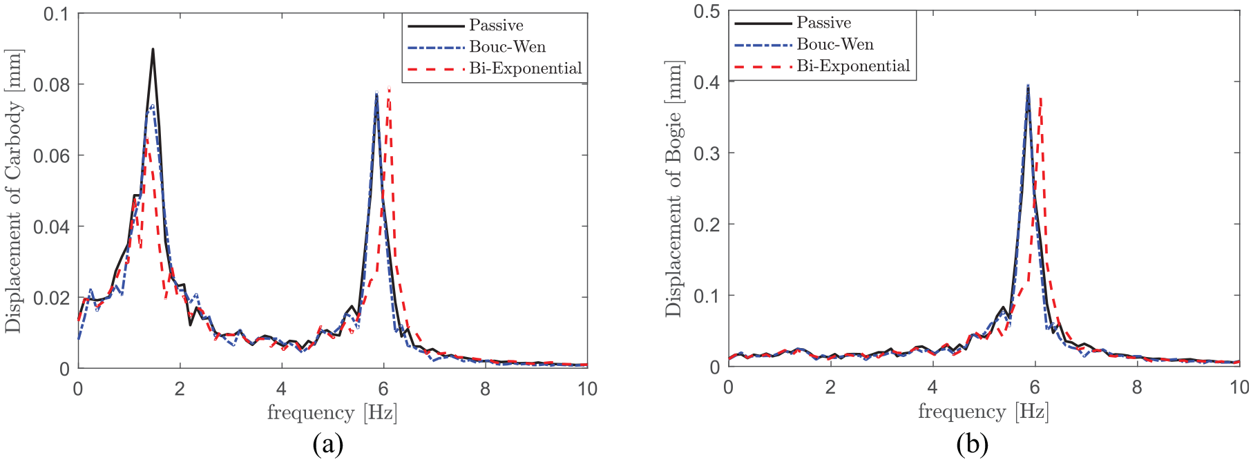
HILS test results of frequency domain of the capsule vehicle: (a) displacement of car body and (b) displacement of bogie.
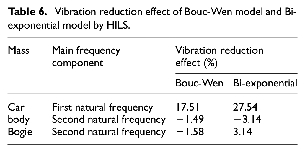
Table 6 shows the quantitative performance differences of the Bouc-Wen and Bi-exponential model applications to the capsule vehicle. It indicates that the Bi-exponential model reduces about 10% more than the Bouc-Wen model in the first natural frequency (1.3–1.5 Hz) component of the car body. However, neither model is effective in the second natural frequency. In the case of the second natural frequency (5.9–6.1 Hz) of the bogie, the application of the Bouc-Wen model does not reduce the vibration at all, but the application of the Bi-exponential model shows a slight reduction. Compared to the simulation results, the application of either the Bouc-Wen or Bi-exponential models results in a poor reduction of vibration in the second natural frequency.
Vibration reduction effect of Bouc-Wen model and Bi-exponential model by HILS.
Conclusion
This paper proposed the Bi-exponential model and its inverse model, which can be easily and simply applied to the semi-active control using the MR damper for the secondary suspension system of the capsule vehicle. It then constructed a 1/4-car capsule vehicle model in the vertical direction and identified the vibration reduction performance through simulation and the HILS test and compared this with the semi-active control results using the Bouc-Wen model. As a result, we derived the following conclusions:
The simulation results showed that the Bi-exponential model was significantly more effective than the Bouc-Wen model for reducing vibration displacement and main frequency components for both the car body and bogie of the capsule vehicle.
The HILS test results showed that the Bi-exponential model was more effective than the Bouc-Wen model for reducing vibration in the first natural frequency, which is the main component of the capsule vehicle’s car body vibration. However, both models were ineffective at reducing vibration in the second natural frequency. For the bogie in the second natural frequency, which is the main vibration component, application of the Bi-exponential model showed a slight reduction in vibration, but the Bouc-Wen model showed no such reduction.
The results of the simulation and HILS test of a 1/4-car capsule vehicle model using an MR damper showed that the Bi-exponential model proposed by this study had a much simpler mathematical expression and performed significantly better overall than the Bouc-Wen model in semi-active control.
While further research is needed to confirm that the Bi-exponential model proposed in this study is always better than the Bouc-Wen model, this paper has confirmed that it has the advantage of being more easily applicable in terms of semi-active control.
Footnotes
Declaration of conflicting interests
The author(s) declared no potential conflicts of interest with respect to the research, authorship, and/or publication of this article.
Funding
The author(s) disclosed receipt of the following financial support for the research, authorship, and/or publication of this article: This research was funded by the Core Technology Development of Subsonic Capsule Train research project, Korea Railroad Research Institute, Korea as part of grant No. PK2101A.