
Abstract
This article deals with the dynamic behavior of a passenger car equipped with an electrically variable transmission, which is analyzed both in time and frequency domains. After deriving the dynamic equations in the state-space form for both open- and closed-loop systems, a methodology for objectively evaluating the drivability of this over-actuated system is proposed. Several simulation results are presented with the aim of highlighting the transient response to fast engine torque changes and the effect of the generator speed controller calibration on the system dynamics. Moreover, the influence of the ratio between electrical and thermal power on the frequency response is discussed. The proposed analysis, which is based on a simple static torque split between internal combustion engine and propulsion electric motor, depicts the dynamic signature of the electrically variable transmission powertrain system, without any additional drivability filter. Hence, these results can constitute the base for the design of dynamic torque splitting aimed at optimizing the longitudinal vehicle response to the driver’s acceleration demand.
Keywords
Introduction
The ever-increasing popularity of hybrid electric vehicles (HEVs) has led to the development of new transmission systems combining electric motors and internal combustion engine (ICE) in an optimized way. An electrically variable transmission (EVT) is a type of power-split transmission used to propel HEVs. It uses two motor-generator units to obtain a continuously variable speed ratio between the engine crankshaft and the wheels, thereby permitting the engine to supply power very efficiently. The strategy to control the energy flow among these multiple sources is termed “energy management” and is crucial for fuel economy.
Most existing works in the literature focus on controllers that try to minimize fuel consumption, neglecting other attributes that affect the smoothness and responsiveness of vehicle, which are commonly referred to as drivability. 1
Vinot et al. 2 use optimal offline management with discrete dynamic programming to evaluate the fuel consumption in the global design process of an EVT, aiming at minimizing fuel consumption and the number of battery cells. Kessels et al. 3 face the optimization of the power flow by means of an integrated powertrain control considering the efficiency of all powertrain components, aiming at energy efficiency. Similarly, other authors focus on different transmission layouts, for example, series 4 or parallel 5 hybrid architectures, always limiting to fuel economy or low emission aspects; Delkhosh et al. 6 present a control strategy that can be used only for hybrid vehicles with Continuously Variable Transmission (CVT), proposing an optimization for different driving cycles.
Taylor and Katariya 7 developed a dynamic model for a two-mode EVT and proposed a control system capable of meeting driver torque demands while also accommodating preferred engine operating points.
Other works 8 discuss different layouts and solutions for EVT transmissions comparing the power performances of each proposal, but also considering some production aspects (costs, ease of manufacture, and sustainability).
Besides energy management tasks, drivability aspects are becoming increasingly important for HEVs. In particular, drivability refers to the powertrain capability of guaranteeing smooth and fast vehicle response to driver requests and to manage the operating mode change without perceptible noise and vibration. These aspects mainly affect the vehicle longitudinal dynamic performance and require finding a trade-off between comfort and sporty feeling also in relation to the specific segment and mission of the car.
In Opila et al., 1 drivability restrictions are directly incorporated in a causal, optimal controller design method for the energy management system of an HEV. The focus is on drivability with respect to engine start-stop and gear shifts; a host of other drivability issues, such as low-frequency longitudinal vibration and other attributes which are typically mitigated by hardware design or low-level control actions, are not considered.
The purpose of the study reported in Galvagno et al. 9 is to assess the drivability of a through-the-road-parallel HEV, with an ICE powering the front axle and an electric motor the rear axle. Through the simulation of a linearized model, the vehicle response to the diver request is analyzed in the time and frequency domain. The effect of the actual gear ratio is investigated and a sensitivity analysis of the influence of the torque distribution between the front (thermal) and rear (electric) axles on vehicle drivability is presented.
In the study by Koprubasi et al., 10 the typical drivability issues of a power-split hybrid-electric vehicle are considered and identified: pedal tip-in and tip-out, change of operating modes, and gear shifting are discussed. The proposed model is useful for the design, improvement, and calibration of control strategies.
The purpose of this article is to present a drivability-oriented dynamic model for the one-mode EVT, which takes into account the effect of the generator speed controller on the vehicle dynamic performance and on the low frequency torsional behavior of the transmission. After presenting the considered powertrain layout and the adopted lumped parameter model, the dynamic and kinematic equations are reported. The final state-space formulations of both uncontrolled (open loop) and controlled system, considering a closed-loop proportional generator speed controller, are shown.
A frequency response function (FRF) suitable for the drivability assessment of this kind of HEV architecture is proposed and then used to evaluate the influence of different parameters. Finally, the transient response during the application of engine torque disturbances is evaluated under different vehicle speeds and controller calibrations.
Series/parallel hybrid electric powertrain
Figure 1(a) shows the powertrain layout of a series/parallel HEV: this powertrain architecture, also known as input-split EVT, allows changing continuously the speed ratio between the engine and the driving wheels. In fact, the generator, in addition to enabling the transfer of mechanical power from the engine to the wheels through the power-split device by absorbing or generating electrical power, realizes a speed ratio controller, as will be shown in the article.

Input-split EVT: (a) layout and (b) mechanical model.
With reference to Figure 1, the ICE E shaft is connected to the planet carrier c of the epicyclic gear set EGS (also known as power-split device) through a torsional damper. The other two mechanical interfaces of the EGS are connected to generator G, via sun gear s, and to electric motor M and final reduction stage of the transmission via the ring gear r. The final reduction stage is composed of a silent chain transmission SC and an ordinary gear train. Finally, the differential gear D splits the transmission output torque to the two half-shafts and allows the transfer of the mechanical power to the driving wheels W of the vehicle.
An appropriate lumped parameter model to study the drivability of the analyzed system is shown in Figure 1(b). The compliances of the transmission system are lumped in three spring and damper elements: one for the torsional damper downstream of the engine and one for each half-shaft. In addition, also the tire torsional flexibility is considered by means of a model that includes the effects of the tire relaxation-length. More details about the modeling process and assumptions are given in the following section.
Dynamic model
The model equations for each powertrain component are here reported.
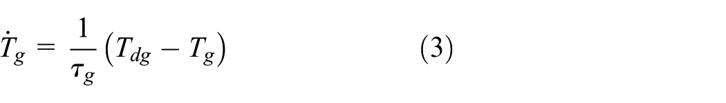
Engine
A first-order differential equation is introduced for modeling the dynamics of the engine torque generation system

where
The second equation of the engine model is the dynamic balance of the moments applied to the engine shaft

Electric generator
For the generator, a first-order model is also used to describe the torque generation system
Newton’s second law applied to the generator rotating inertia gives

where
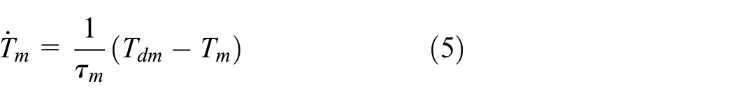
Electric motor
Similar to the other actuators, the delay due to the electric motor torque control system is modeled as follows

where
Primary shaft

Secondary shaft

Differential

Driving wheels (front axle)

Tire model
The linearization of the tires longitudinal force versus slip steady-state characteristic,
11
valid for low slip values, leads to an equivalent viscous damper with viscous friction coefficient


where

where
Vehicle
The dynamic balance of the vehicle longitudinal motion reflected to the front wheels axis gives

where
Since the rear wheels are not driven, their behavior can be described using a simplified pure rolling model, that is

Since both rolling and aerodynamic resistances are nonlinear functions of the state variables, they need to be linearized as clarified later in a specific section.
EGS
Considering a unitary efficiency and neglecting the inertia of the inner components of the gear set, the following torque equations hold


where subscripts s, r, and c represent sun gear, ring gear, and planet carrier of the planetary gear set, respectively. R is the pitch radius of the gears. See Velardocchia et al. 12 and Galvagno 13 for mathematical models of epicyclical gears including also mesh efficiency, bearings/seals losses, and inertial effects.
The gear train kinematic equation is
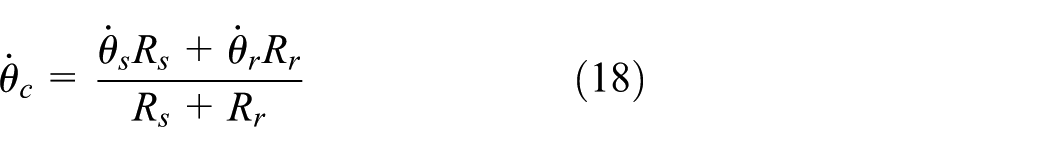
Since the generator is connected to the sun gear, the electric motor to the ring gear, and the carrier to the engine through the torsional damper, the former equation can be rewritten as follows under steady-state condition

From this kinematic equation, the possibility to control the engine speed through the electric generator becomes evident. The engine speed is a weighted mean of the generator and the motor/vehicle speed where the weights are functions of the gears radii. The parameter
Linearization of the external forces
Rolling resistance is generally modeled as a quadratic function of the wheel speed and aerodynamic force as a quadratic function of the vehicle speed. A constant weight distribution between front and rear axle is considered, hence the longitudinal load transfer is neglected. The linearization of these functions gives

where
The expressions of the constants of linearization are reported in Appendix 1.
The linearization process of the system nonlinearities leads to different parameter values and consequently different system response for different vehicle speed as will be discussed in the “Simulation results” section.
State-space model of the uncontrolled system
The continuous time-invariant state-space representation of the uncontrolled mechanical system, that is, considering as input the torque requests to the three actuators, is
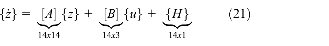
where the state vector

The input vector

The dynamic matrix
Generator speed controller
Different from more traditional mechanical transmissions, for example, MT, AT, and DCT, an EVT does not represent a mechanical constraint for the speed ratio between engine and wheels. The generator accomplishes this specific objective: by controlling its shaft speed, it varies the ratio between the transmission input and output speeds. Moreover, it is of interest noting that while the speed ratio of the EVT can be continuously adjusted through the generator control, the torque ratio is constant and dependent on the mechanical parameters of the system.
In order to study the dynamic behavior of an EVT-equipped vehicle, it is therefore necessary to consider also the generator speed controller

The generator torque demand
Introducing a target overall speed ratio

The target ratio
The equation for calculating the generator speed set point

The engine speed and the electric motors speeds are available measures that are used as known quantities by the control system.
Hence, the reference speed for the generator can be easily computed and introduced in equation (24) to obtain the generator torque as a function of inputs and states

Inserting the former equation in equation (3), a new equation for the state space becomes available. Hence,
Therefore, the state-space formulation of the controlled mechanical system has a reduced number of inputs, that are the torque demand for the engine and the electric motor, while the target speed ratio enters as a parameter in the dynamic matrix

Powertrain torque control
Since the aim of this research is to investigate the “passive” dynamic behavior of an EVT-equipped vehicle, that is, in absence of drivability control, we assume to proportionally distribute the total effort requested at the wheels according to the energy management control strategy requirements. A simple gain between the desired engine torque and the desired electric motor torque is imposed, that is

It must be noted that a dynamic correction G(s) could be designed in order to tune the desired drivability performance of the vehicle, that is,
At the same time, the generator exerts the reaction torque to the epicyclic gear train needed to enable the transfer of engine power to the wheels, according to its control logic explained in the former section.
In order to quantify the contribution to the vehicle propulsion of the engine and the electric motor, a parameter p is introduced. It represents the percentage of the total tractive torque, delivered at the drive wheels Tw by the engine in steady-state conditions.
The steady-state torque contributions of the actuators evaluated at the wheels can be easily obtained starting from the dynamic equations

Dividing equation (30) by

Isolating the engine and electric motor terms
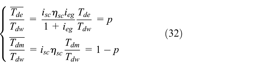
Consequently, if p = 1 the vehicle utilizes only the engine (and the generator) torque to propel the vehicle, whereas if p = 0 the vehicle is running in pure electric mode.
Finally, the following equations can be used to evaluate the engine torque demand and the electric motor torque demand from a given desired wheel torque and percentage of utilization p

Frequency response function for drivability assessment
Vehicle longitudinal acceleration is one of the most important quantities that is commonly used for the evaluation of the drivability of a vehicle because it can be strictly correlated to both comfort and sportiness perceived by the passengers of a car.
As it has been done for the drivability assessment of other HEV architectures, 9 a transfer function to characterize the drivability performance of the EVT-equipped vehicle must be carefully chosen. It correlates the torque total request at the wheels, coming from the driver, to the actual response of the vehicle, in terms of longitudinal acceleration.
Since the system is over-actuated, this drivability transfer function cannot be derived immediately but requires some assumptions. A static torque split is applied also in this case, thus allowing to study the system response to synchronous harmonic excitations (same frequency and same phase) applied by the i.c. engine and the electric propulsion motor. The amplitude ratio between the two exciting torques is regulated by a torque distribution parameter.
From the mathematical point of view, the vehicle response to a driver request of acceleration can be evaluated starting from the transfer function between the wheel torque demand
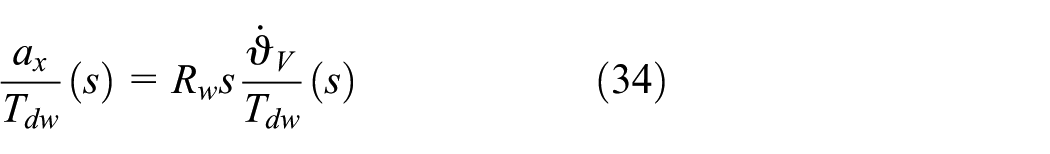
where
Under the hypothesis of linear system and static torque split between the electric and thermal actuators, according to equation (33), the superposition principle can be applied, that is, the resulting FRF is the sum of the contributions of the two inputs

Dividing by

Introducing the former equation in equation (34) and rearranging to highlight the effect of the parameter p on the resulting FRF, we obtain

Since we have considered a closed loop control of the generator speed directly implemented in the state-space model, the generator torque does not appear explicitly in the previous equation since its dynamic contribution is automatically included in the other two transfer functions. The calibration of the generator control plays an important role on the system dynamic performance as will be demonstrated in the “Simulation results” section.
Simulation results
In this section, the dynamic behavior of a vehicle equipped with an EVT is investigated through numerical simulation in both time and frequency domain.
The time domain simulated maneuver is a step change of the torques applied synchronously by the actuators. The engine torque demand changes from 0 to 100 N m at second 1 of the simulation and the percentage of distribution between the actuators is p = 50%.
The frequency domain analysis is focused on the acceleration response of the vehicle to in-phase harmonic excitations applied to the inputs.
In particular, the effects of the generator control calibration, the torque distribution between the electric motor and the i.c. engine, and the vehicle speed are analyzed in detail. Two plots for each sensitivity analysis are shown: the first is obtained considering low vehicle speed (30 km/h), for example, driving in city traffic, the second considering high speed (130 km/h), for example, driving on highways.
Effect of generator speed control
As already mentioned in the generator control section, a proportional speed controller is assumed. Figures 2 and 3 show the effect of the proportional gain on the FRF expressed by equation (37) and imposing p = 50%.

Frequency response function

Frequency response function
Looking at Figure 2, the effect of the proportional gain can be summarized as follows:
For low
For high
Figure 3 shows the same FRFs but evaluated for a higher initial vehicle speed, that is, 130 km/h. The change occurred in the parameters values, due to system nonlinearities, led to FRF magnitude that is much lower than the previous case in the whole frequency range. The increased damping is mainly due to a reduction of the viscous friction coefficient of front tires β t , which allows more tire slip and so a greater amount of vibrational energy dissipation. Moreover, the damping due to aerodynamic and rolling resistances increases quadratically with the vehicle speed; although these last damping parameters related to motion resistance are much higher in the high speed case, their quantitative effect is more limited if compared with tire damping. Same considerations done for the low speed maneuver, concerning the effect of Kp also apply to this case.
Comparing the results in the frequency domain, it can be noted that Kp = 0.8 gives very good dynamic performance, since it allows minimizing the H-infinity norm of the FRF, that is, its maximum magnitude over the considered frequency range, in both the low and high speed maneuvers. This parameter setting ensures high operating bandwidth with fast transient oscillation damping.
Figures 4–6 show the effect of the proportional gain on the time history of the vehicle acceleration and of the actual speed ratio during Tip-In. The test specifications are step change from 0 to 100 N m of the engine torque demand and constant torque distribution p = 50%.

Vehicle acceleration (on the left) and actual speed ratio (on the right) during a Tip-In test at 30 km/h with p = 50%: effect of the proportional gain of the generator speed controller.

Vehicle acceleration (on the left) and actual speed ratio (on the right) during a Tip-In test at 130 km/h with p = 50%: effect of the proportional gain of the generator speed controller.

Actual speed ratio versus time during Tip-In tests carried out at different vehicle speed while keeping the same calibration of the generator speed controller, ζ = 0,85.
Also from this point of view, evidently the optimal system response is obtained using an intermediate value of the proportional gain, that is, 0.8. In fact, both higher and lower values lead to higher overshoot, undershoot, and settling time of the vehicle acceleration, therefore worsening the system dynamic performance. In addition, looking at the speed ratio versus time plot, it can be noted that the tracking and disturbance rejection performance of the speed ratio controller is optimized for this gain choice. Comparing Figure 4 with Figure 5, it can be observed that the considered Tip-In maneuver is less critical at high cruising speed, because once again the higher the vehicle speed the higher the damping effect due to tire slip and motion resistance on the system dynamics.
Figure 6 depicts the instantaneous speed ratio computed during four tip-in tests, each carried out at a different vehicle speed (20, 50, 80, 110 km/h). From this graph, the effect of the vehicle speed on the performance of the generator controller (with constant calibration
Effect of the torque distribution between the actuators
The effect of the torque distribution between the thermal and the electric actuators on the FRF is shown in the upper part of Figure 7 for low speed and in the lower part for high speed.

FRFs
At low speed, two resonance peaks are clearly visible in the FRFs. The frequency and damping of the first peak is quite insensitive to the variation of the parameter p, while the damping of the second mode increases substantially by increasing the engine torque contribution. The fully electric operating mode shows a more critical dynamic behavior with respect to the pure thermal mode due to a loosely damped second vibration mode.
At high speed, see the lower part of Figure 7, only the peak associated with the lowest torsional mode of the system can be seen. The second mode is highly damped and cannot be directly identified from this specific FRF, while the first mode gives origin to a peak whose magnitude slightly decreases as p decreases. Hence, contrarily to what happens at low vehicle speed, the increase in the electric motor contribution improves the dynamic response of the vehicle.
Conclusion
In this article, a dynamic analysis of an EVT-equipped powertrain is presented. After deriving the dynamic equations in the state-space form for both open- and closed-loop systems, a methodology for objectively evaluating the drivability of this overactuated system has been proposed. A synchronous excitation from the engine and the electric propulsion motor is assumed, while the generator torque is the output of a feedback controller aiming at keeping constant the speed ratio between the engine and transmission output shaft.
The dynamic system behavior, investigated through numerical simulation in both time and frequency domains, has some interesting features that can be summarized as follows:
The calibration of generator speed controller plays an essential role in the definition of the dynamic system response, especially during low-speed maneuvers. As an example, it has been shown that the optimal selection of the proportional gain of the feedback controller ensures high operating bandwidth with fast transient oscillation damping.
At high vehicle speeds, a greater damping of the system is observed. This in general leads to a more damped drivability FRF and therefore to less vibration issues.
The generator speed control is less effective at low speed, while it becomes progressively more insensitive to the disturbances introduced by the torque steps of the other actuators with increasing velocity.
The effect of the electric motor torque contribution is different depending on the vehicle speed range. At low speed, the fully electric operating mode shows a more critical dynamic behavior with respect to the pure thermal mode due to the presence of a loosely damped second vibration mode. Conversely, at high speed, the increase in the electric motor contribution improves the dynamic response of the vehicle; a flatter passband is obtained together with a higher bandwidth.
Footnotes
Appendix 1
Linearization constant expressions
Handling Editor: Ling Zheng
Declaration of conflicting interests
The author(s) declared no potential conflicts of interest with respect to the research, authorship, and/or publication of this article.
Funding
The author(s) received no financial support for the research, authorship, and/or publication of this article.