
Abstract
The rotational performance of the spindle-bearing system has critical influence upon the geometric shape and surface roughness of the machined parts. The effects of preload and preload method on the rotational performance of the spindle-bearing system is explored experimentally to reveal the role of preload and preload method in spindle rotational performances under different speeds. A test rig on which both the rigid preload and elastic preload can be realized, equipped with variable preload spindle-bearing system, is developed. Based on the mechanical model, the relationship of the axial preload and negative axial clearance of the spindle-bearing system is provided. Rotating sensitive radial error motion tests are conducted for evaluating synchronous and asynchronous radial errors of the variable preload spindle-bearing system under different rotating speeds and preload methods. The change regularity of synchronous and asynchronous radial errors with preloads under different rotating speeds are given. The results show that the preload plays an important role on the rotational performance of spindle-bearing system. The rigid preload is more efficient in achieving better rotational performance than elastic preload under the same rotating speed. Furthermore, this article significantly guides the preload designing and assembling of the new spindle-bearing system.
Keywords
Introduction
The rotational performance of the spindle-bearing system has critical influence upon the geometric shape and surface roughness of the machined parts and becomes an important technical indicator when evaluating the dynamic performance of the spindle.1,2 In order to select an optimum preload of the spindle-bearing system in spindle assembling process, good understanding of the change regularity of rotational performances with preload and rotating speeds under different preload methods is essential.
In recent years, many studies have been conducted to study the effects of the preload on the performance of the spindle-bearing system. Literature review shows that some researchers have investigated the effect of the preload on the dynamic characteristics of the spindle system,3–9 and found that high preload of the bearing can enhance the stiffness and the natural frequency of the spindle. Other works have focused on the effects of bearing preload on the thermal behaviors of the spindle.10–16
The existing preload methods of the spindle-bearing system are categorized into two types according to the stiffness of the preload mechanism: rigid preload and elastic preload.17,18 Rigid preload (Fixed position preload), is applied by inducing a constant relative displacement between the inner and outer rings by using match-ground bearing sets or two ground spacers whose heights are different. Elastic preload is exerted by utilizing springs. 19 However, the preload is exerted in spindle assembling process and the value of the preload cannot be re-adjusted after the spindle assembling process is completed. Therefore, many studies have been conducted to study the variable preload technology. The researches are mainly focused on the design of the preload mechanism20–22 and the determination of the optimum preload. 11 The application of variable preload mechanism in practice is uncommon because the variable preload technology is still in research stage. 3
Yang et al. 23 and Chen et al. 24 developed an instrument to analyze the rotational accuracy of high-precision rolling element bearing. A pneumatic mechanism was utilized to adjust the preload. The rotational accuracy of a single bearing rather than the spindle-bearing system has been measured. Kim and Kim 2 investigated the effect of the preload on the rotational accuracy under different speeds. Kim et al. 25 investigated the effect of the preload on the run-out of the spindle under different speeds. However, they did not consider the rigid preload case. Li et al. 26 investigated the non-uniform preload on the rotational performance and provided a new compensation method to spindle rotational error.
It is worth noting that in these studies, few investigations have been performed on sensitivity of rotational performance to different preloads and preload methods. Therefore, it is essential to develop a preload measurement and adjustment system, on which rigid preload and elastic preload can be realized, as well as radial error measurement system so as to study the effects of preload on the rotational accuracy of the spindle-bearing system.
In this article, the effects of the assembling preload (initial preload or preload after assembly) on the rotational performances of the spindle-bearing system under different preload methods is investigated experimentally. In the “Variable preload spindle-bearing system” section, a variable spindle-bearing system with preload adjustment mechanism is proposed for investigating different preload methods. Based on the mechanical model of spindle-bearing system, the relationship of the axial preload and negative axial clearance of the spindle-bearing system is provided. The centrifugal force induced preload and the radial stiffness of the spindle-bearing system are calculated and analyzed. In the “Test method and measurement system” section, the preload measurement and adjustment system, as well as radial error measurement system are established. In the section “Experimental analysis,” a series of experiments are carried out for evaluating the radial errors of the spindle-bearing system. The effects of preload and preload method, as well as the rotating speed on the synchronous and asynchronous radial errors are analyzed. The change regularity of rotational performance with preloads under different rotating speeds are given. The final section gives some conclusions and suggestions for future research.
Variable preload spindle-bearing system
Concept and operation principles
In order to investigate the effects of variable preload and preload method on the rotational performance of spindle-bearing system, a variable preload test rig is developed. The detailed structures are shown in Figure 1. A high-precision motorized spindle is utilized to drive the variable preload test rig. The rated speed of the test rig is 8000 r/min. Rigid and elastic preload mechanisms are installed on the test rig.

The detailed structure of the variable preload test rig.
The rotor is supported by two pairs of universal combination angular contact bearings. The front and rear bearings are double tandem arrangement, but in opposite direction (double O configurations). The rear sleeve can slide along the Z-axis freely, while the front sleeve is fixed. All the bearings are restrained along the radial direction. Three preload springs are distributed evenly along the circumferential circle of the rear sleeve. The adjustable fine thread bolt (7, 8, 9), preload spring, and force sensor are mounted in series. The output forces of the preload springs, denoted by Fp1, Fp2, and Fp3, are evenly distributed on the rear sleeve and can be adjusted by the adjustable fine thread bolt 7, 8, 9. There are six adjustable fine thread screws and three high-precision capacitive displacement sensors installed on rear sleeve.
Variable preloads are applied as follows. As to elastic preload method, the preload forces are exerted on the rear sleeve by screwing the three adjustable fine thread bolts (7, 8, 9) circularly. The preload is then transferred to the rear bearings, rotor, and front bearings due to the elastic force of the springs. The elastic force of one preload spring can be measured/adjusted by the force sensor/adjustable fine thread bolt. When the spindle-bearing system reaches a self-balanced state in Z-axis direction, both front and rear bearings are preloaded. The actual preload (preload in rotating state) under elastic preload method depends on the spring stiffness. If the axial stiffness of the bearing is much larger than the preload spring, the actual preload of the spindle-bearing system can be treated as a constant value.
The elastic preload spindle-bearing system can be switched to the rigid preload spindle-bearing system easily. The rigid preload method is implemented by screwing the six adjustable fine thread screws circularly. The negative axial clearance of four bearings, denoted by D1, D2, and D3, respectively, can be measured/adjusted by the capacitive displacement sensors/adjustable fine thread screw 1, 2, 3. The relationship between the preload and negative axial clearance can be achieved by the elastic preload method. The position of the rear sleeve can be adjusted and fixed by utilizing the adjustable fine thread screws 4, 5, and 6. It is noted that, fixing the rear sleeve on the test bed at the desired position is an iterative process.
If Fp1, Fp2, and Fp3 or D1, D2, and D3 are equal to each other, the preloads are evenly and uniformly distributed on the rear sleeve, while Fp1, Fp2, and Fp3 or D1, D2, and D3 are not equal to each other, the preloads are applied non-uniformly to the rear sleeve. In this article, we only investigate the uniform preload. The variable preload control technology lays the foundation for investigating the non-uniform preload.
Mechanical model of the variable spindle-bearing system
The mechanical model of the variable spindle-bearing system is illustrated in Figure 2. In mechanical domain, the preload spring can be treated as an elastic component with constant stiffness, denoted by kp. The bearing can be simplified as a nonlinear spring according to the Hertz contact theory, whose stiffness can be equivalent to axial stiffness and radial stiffness. 27 The contact stiffness Ks between the rear sleeve and the base can be derived by literature. 28

The mechanical model of variable preload spindle-bearing system.
According to the measured axial clearances, three types of bearings with different preloads (EL, L, M) are provided by NSK, Inc. In engineering application, in order to change preload, we could adjust the axial clearance by a spacer. Since the bearing preload and structure parameter are the important factors for the spindle-bearing system, the bearing parameters and the recommended preload values are specifically tabulated in Table 1. The recommended preload value represents that on one single ball bearing only. As the spindle system is installed with double O configuration form, the recommended preload value is twice as the preload for the single bearing according to the NSK bearing handbook.
Parameters and recommended preload value of the selected bearing (Model: NSK 65BNR10H SUELP4Y).

d: inner diameter; D: outer diameter; αo: initial contact angle; Z: number of rolling element; Dw: diameter of rolling element; fo: outer groove curvature radius coefficient; fi: inner groove curvature radius coefficient; dm: pitch diameter; EL: extreme light preload; L: light preload; M: middle preload.
The relationship between the preload and negative axial clearance in static state
The axial displacement of the rear sleeve 2δa represents the negative axial clearance of four bearing combinations where δa is the relative motion of the inner ring with respect to the outer ring of the bearing. The bearing stiffness is a series stiffness combination of the ball/inner-raceway contact load and ball/outer-raceway contact load. That is 29

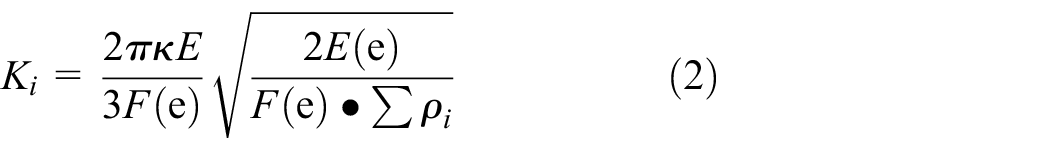
where Ki and Ko are the load-displacement coefficients for ball and outer/inner raceways, respectively. Ki and Ko can be obtained by equations (2) and (4).
Based on the Hertz contact theory, 29 the inner ring contact stiffness Ki is
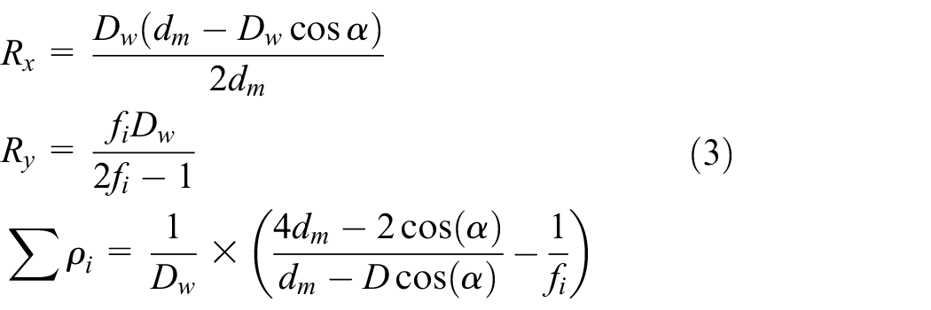
where Rx and Ry are the parameters that depend on the ball and inner ring, ∑ρi is the curvature sum of the inner raceway and ball
The outer ring contact stiffness, Ko is

where Rx and Ry are the parameters that depend on the ball and outer ring, ∑ρo is the curvature sum of the outer raceway and ball
E (in equations (2) and (4)) is the equivalent elastic modulus of the Hertz contact and can be obtained by equation (6)

where E1 and E2 are the elastic modulus of the ring and ceramic rolling element, respectively, and u1 and u2 are the Poisson’s ratios of the ring and ceramic rolling element, respectively.
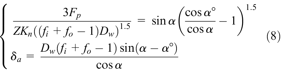
Based on the linear regressive equation of Brewe and Hamrock 29

Substituting equation (1) in equation (7), one can get the relationship of the axial preload and axial displacement using Newton–Raphson method
where

Figure 3 illustrates the relationship of the axial preload and negative axial clearance of the spindle-bearing system under different preloads. When the negative axial clearance of the rear sleeve is set to 10 μm in rigid preload method, the equivalent preload value in elastic preload method is 280 N. Similarly, when the negative axial clearance of the rear sleeve is set to 20 μm, the equivalent preload value is 826 N.
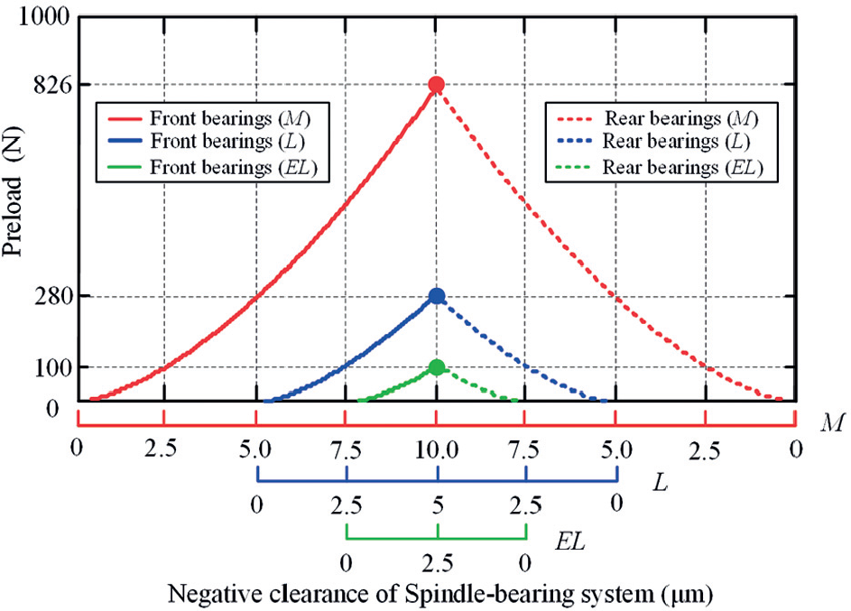
The relationship of the axial preload and negative axial clearance of the spindle-bearing system.
The radial stiffness of the spindle-bearing system in rotational state
The rotational accuracy of the spindle-bearing system is an important technical indicator when evaluating the dynamic performance of the spindle.1,2 From the dynamic point of view, the radial stiffness of the bearing plays an important role in the rotational accuracy of the spindle-bearing system. The bearing preload has a great influence on spindle stiffness. In order to calculate the radial stiffness of the bearing in rotational state, actual preload of the bearing is essential. As to elastic preload, the thermally induced preload and centrifugal induced preload can be absorbed by the preload spring as the axial stiffness of the bearing is much larger than the spring. The preload in rotational state and the assembling preload are nearly equal to each other. However, as to rigid preload, because the axial stiffness of the bearing is smaller than the preload mechanism, the preload in rotational state depends on the assembling preload, the centrifugal induced preload, and the thermally induced preload. In rotational state, the thermally induced preload and the centrifugal force induced preload exist at the same time. Thermally induced preloads have not been considered and calculated, since they involve more complicated issues and the rotating speed in this study is not very high. The effect of thermally induced preload on the running accuracy will be studied in future.
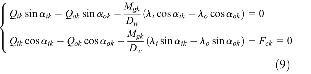
Figure 4 shows the positions of the ball center and raceway groove curvature centers. Figure 5 shows the axial loads equilibrium graph of a single angular contact ball bearing. There are a gyroscopic moment and two loads that act on the bearing in rotational state. 3Fp / Z is the axial preload on a single ball, Fck is the centrifugal force. The summed bearing load on a single ball in rotational state will be the summation of 3Fp / Z, and Fck, if the thermal effect is excluded. The equilibrium of the loads acting on the kth ball in the horizontal and vertical directions can be stated as 29
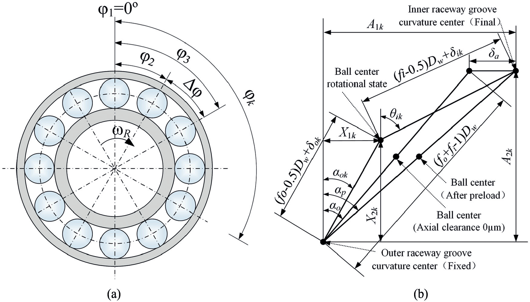
Positions of the ball center and raceway groove curvature centers: (a) angular position of the bearing ball and (b) ball center and raceway groove curvature centers at angular position
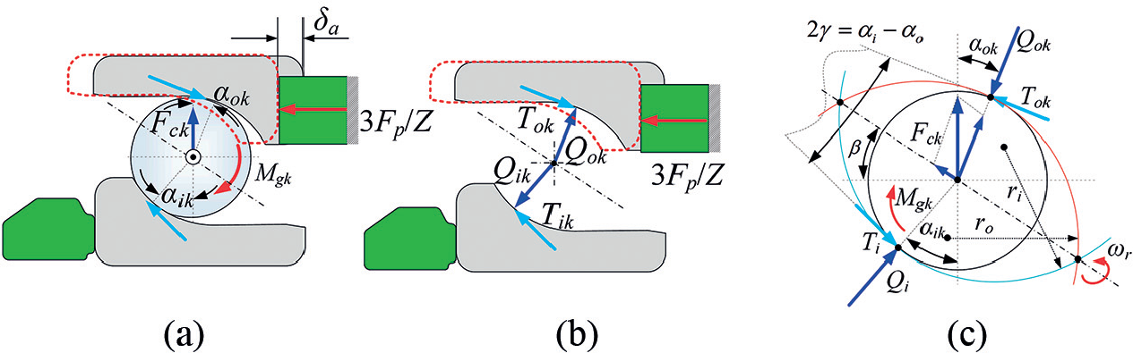
Axial loads equilibrium graph of a single angular contact ball bearing: (a) loads acting on bearing, (b) equilibrium of bearing rings, and (c) equilibrium of bearing ball.
The normal contact force at the inner and outer raceway can be stated as

where Qi(o)k is the contact load between the inner (outer) ring and the kth ball, Ki(o)k is the coefficient of the load-displacement between the inner (outer) ring and the kth ball. δi(o)k is the contact deformation of the inner (outer) ring. As to outer raceway control, λi = 0, Tik = 0; λo = 2, Tok = 2Mg / Dw. The gyroscopic moment Mgk and centrifugal force Fck acting on the kth ball can be described by as follows 29

where ω R is the rotational speed of the rotor, ωr is the angular velocity of the ball, and ωb is the angular velocity of the bearing cage.
The axial distance between the position of outer and inner raceway groove curvature centers is

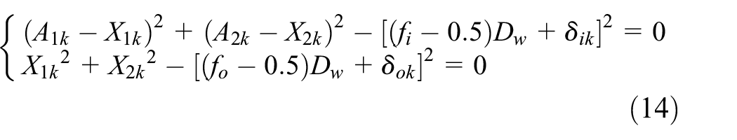
New variables X1 and X2 are introduced as seen from Figure 4(b)

Using the Pythagorean theorem, it can be seen from Figure 4(b) that

Equation (15) is highly coupled and nonlinear, and can be solved by using Newton–Raphson numerical method. As to rigid preload, assume that the stiffness of Kp is infinite and the negative axial clearance δa is given, the actual rigid preload Fa can be calculated. As to elastic preload, if the preload is constant, the actual negative axial clearance δaa can be calculated. The actual preload of the spindle-bearing system under different speeds is illustrated in Figure 6(a).

The actual preload and radial stiffness of the spindle-bearing system under different speeds: (a) actual preload and (b) radial stiffness.
The bearing radial stiffness under preload can be calculated by equation (16)

where

where φk is the angular position of the kth ball in the global coordinate as shown in Figure 4(a) and Fa is the actual preload of the bearing. As to rigid preload, δaa is the axial displacement under preload Fa in the static state and δa is the initial negative axial clearance under preload 3Fp. As to elastic preload, δaa is the axial displacement under preload 3Fp in the rotational state and δa is the initial negative axial clearance under preload 3Fp. The actual radial stiffness of the spindle-bearing system under different speeds is illustrated in Figure 6(b).
As shown in Figure 6(a), as to elastic preload, the actual preload is a constant value (equal to the assembling preload). However, as to rigid preload, the actual preload increases with the speed due to the centrifugal induced preload. Figure 6(b) shows the change regularity of radial stiffness with rotational speed under different preloads and preload methods. It can be seen that with the speed increases, the radial stiffness of the bearing drops in both preload methods. The reason is that the bearing stiffness is a series stiffness combination (ball/inner ring contact stiffness and ball/outer ring contact stiffness). The contact stiffness between ball and outer ring increases while the contact stiffness between ball and inner ring decreases due to the centrifugal force. Therefore, the total radial stiffness decreases with the rotational speed continuously. The drop phenomenon is more significant under elastic preload method as spindle-bearing system with elastic preload allows the bearing rings to change their relative axial position as reported in Cao et al. 9 In other words, compared to elastic preload, the rigid preload is more efficient in achieving higher radial stiffness.
Test method and measurement system
Test method of the rotational accuracy
Conventional measurement methods of spindle rotating accuracy include static method, single-direction method, and two-direction method. 30 In this article, rotation is in the sensitive direction of the rotor, so two-direction method is utilized. The schematic of two-direction measurement method is shown in Figure 7. Two orthogonal capacitive displacement sensors are applied to inspect the radial error motion. The displacement signals acquired by the capacitive displacement sensor A and B, are ΔX(θ) and ΔY(θ), respectively.


where δx and δy are the rotor error motion in X and Y direction,
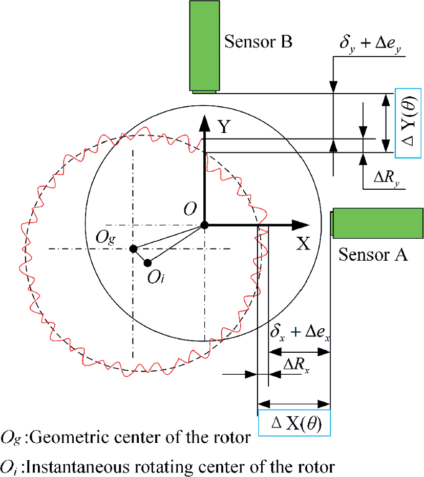
Schematic of two-direction measurement method.
The vector diagram of rotational accuracy for sensitive direction is shown in Figure 8.

The vector diagram of rotational accuracy for sensitive direction.
According to the geometric relationship of the vector diagram, the following equations can be obtained apparently


The radial error motion at angular position θ can be calculated by equation (24)

where r0 is the value of the basic circle radius set by alignment of the displacement sensors and the rotor. By adjusting the value of r0, the plot of the error motion would be easy to identify, without affecting error motion value.
Measurement system of rotational performance
Figure 9 shows the monolithic preload measurement and adjustment system as well as radial error measurement system used for measuring the rotational accuracy of the test rig. The system consists of NI DAQ Card (USB-6356), force sensors (HBM-C9C from HBM, Inc.) including the amplifier, and capacitive displacement sensors (C8-2.0 Lion, Inc.) including the amplifier. All the devices are placed on a vibration-isolated table. Table 2 shows the measuring conditions in this experiment. The experiment is conducted under the middle preload (both rigid preload method and elastic preload method) continuously when the temperature is stable, so the thermal effect on the rotational accuracy is neglected.

Photograph of the measurement system.
Measuring conditions.

Experimental analysis
Preload–negative axial clearance experiments for variable spindle-bearing system
The comparisons of the measured and simulated values of the preload and negative axial clearance are shown in Figure 10. It can be seen that, with the preload increases from 0 to 826 N, the negative axial clearance of the rear sleeve and rotor increase with a same tendency. For a given preload value, the negative axial clearance of the rear sleeve is approximately twice as large as that of the rotor. The simulated values are in good accordance with the experimental results. However, D1 is 3 μm larger than D2 and D3. The reason is that the actual bearing preload is distributed non-uniformly along the circumference of the outer bearing ring due to the gravity of the rotor.

Verification of preload–negative axial clearance.
Evaluation of the radial error for variable spindle-bearing system
In accordance with ANSI/ASME standard or ISO standard,31,32 total error motion polar plots can be plotted by using the data of displacement sensors as shown in Figure 11(a). Least square circle (LSC) evaluation method is used to assess the synchronous radial error of the rotor. Actually, the calculation of synchronous error motion value is a process of nonlinear least square fitting. The calculation process is expressed in equation (25)

where θ is the corresponding angular position of sampling and RLSC is the radius of LSC.

Error motion polar plots at spindle speed of 3000 r/min (rigid preload 826 N): (a) total error motion polar plots, (b) synchronous radial error motion polar plots, and (c) asynchronous radial error motion polar plots.
From the LSC center, a circumscribed circle and an inscribed circle can be obtained. The radial width between the circumscribed circle and inscribed circle is determined as the synchronous radial error of the spindle-bearing system as illustrated in Figure 11(b).
Synchronous error motion value δsync can be calculated by equation (26)

where RCSC and RISC are the radius of the circumscribed circle and the inscribed circle, respectively.
Figure 11(c) shows the asynchronous error motion polar plots. Asynchronous error motion value is the maximum scaled width of asynchronous error motion polar plot, measured along a radial line through the polar chart center at any angular position around circumference. Asynchronous error motion value δsync can be calculated as follows

where
Results and discussion
To demonstrate the effects of the preload and preload method on the rotational performance, a series of measurements are performed under different speeds and axial preloads.
In order to reduce the random errors and increase the reliability and repeatability of the measurement, the radial error motion values were measured five times at the same speed and preload. Tables 3 and 4 show the evaluation of synchronous and asynchronous radial error motion values at different speeds under the light preload (280 N/10 µm) in both rigid preload method and elastic preload method. The average values and standard deviations (SD) of five measurements at each speed are also listed in Tables 3 and 4.
Evaluated values for synchronous radial error at different spindle speeds (Preload: L).

Evaluated values for asynchronous radial error at different spindle speeds (Preload: L).

Tables 5 and 6 show the synchronous and asynchronous error motions values for the variable preload test rig under various spindle speeds and axial preloads.
Evaluated values for synchronous radial error under different spindle speeds and preloads (μm).

Evaluated values for asynchronous radial error under different spindle speeds and preloads (μm).

Figure 12 illustrates the relationships between synchronous/asynchronous radial errors and rotational speed under different preloads. It can be seen that, when the rotor rotates at low speed, the synchronous errors do not show significant variations for the given preload and preload method. When the rotation speed is higher than this range, an increasing trend is observed for the synchronous radial errors. Unlike the synchronous radial errors, the asynchronous errors increase with the increase of rotational speed for the given preload in both preload methods. With the preload increases, the synchronous and asynchronous radial errors decrease obviously at a given rotational speed.

Evaluated values for synchronous and asynchronous errors at different speeds: (a) synchronous radial error (µm) and (b) asynchronous radial error (µm).
Synchronous radial error, which represents the repetitive behavior of spindle-bearing system, is caused due to the roundness of the ball and the raceway of the bearing. Asynchronous radial error is caused by imperfections and defects in the balls and raceway of the bearing. 30 From the dynamics point of view, the radial stiffness plays a significant role to reduce the vibration levels of the rotor and consequently results in better rotational accuracy. The general trend of synchronous/asynchronous radial errors is contrary to the trend of radial stiffness under different preloads and rotational speeds. With the increase of rotating speed, the radial stiffness of the spindle-bearing system decreases gradually for a given preload/negative axial clearance. This decreases the capability of the bearing to reduce rotor vibration levels. That is why the synchronous and asynchronous errors increase with the increases of rotational speed. When the rotating speed is given, the radial stiffness of the spindle-bearing system increases due to the Hertz contact area between the ball and the raceway being flattened by the increase of preload. Consequently, it leads to the reduction in the evaluated value of synchronous and asynchronous radial errors of the spindle-bearing system.
Attention should be drawn to the deviation value of the synchronous/asynchronous errors between the rigid preload method and elastic preload method. The synchronous/asynchronous errors of the spindle-bearing system in rigid preload method is smaller than that in elastic preload method for a given speed. As mentioned above, the rigid preload is more efficient in achieving higher radial stiffness in rotational state due to the centrifugal induced preload. For a given rotational speed, the radial stiffness in rigid preload method is larger than in elastic preload method. This is the reason why the synchronous/asynchronous radial errors in elastic preload method is larger than that in rigid preload method. With the speed increase, the deviation value of radial stiffness between the two preload methods is becoming gradually larger due to the spindle-bearing system with elastic preload allowing the bearing rings to change their relative axial position. Consequently, the deviation value of the synchronous and asynchronous errors between the two preload methods is becoming gradually larger.
Conclusion
This article mainly investigates the effect of preloads and preload methods on the rotational performance of the spindle-bearing system by means of experiment. A new test rig equipped with variable preload spindle-bearing system is developed. Not only rigid preload but also elastic preload can be realized on the test rig. The mechanical model of the variable preload spindle-bearing system under different preload methods is established. Based on the model, the correspondence between preload and negative axial clearance of the spindle-bearing system is provided. The radial stiffness of the spindle-bearing system in rotational state are calculated and analyzed. The preload measurement and adjustment system, as well as radial error measurement system are established. Based on the measurement system, rotating sensitive radial error motion tests are carried out for evaluating the radial errors of the spindle-bearing system. The synchronous and asynchronous radial errors are found to be greatly affected by the preload. With the preload increases, the synchronous and asynchronous radial errors decrease obviously at the same speed. In addition, as the rotational speed increases, the deviation value of the synchronous and asynchronous errors between the two preload methods is becoming gradually larger, and the rigid preload has a certain advantage in achieving better rotational performance.
In order to find the optimum preload of the spindle-bearing system under different speeds, the effects of the temperature on the rotational performance in both preload methods will be further studied in the future. It is also important to develop a variable preload mechanism to control the preload or negative axial clearance in alternating machining process actively.
Footnotes
Acknowledgements
The authors thank the reviewers for their comments.
Handling Editor: Jan Torgersen
Declaration of conflicting interests
The author(s) declared no potential conflicts of interest with respect to the research, authorship, and/or publication of this article.
Funding
The author(s) disclosed receipt of the following financial support for the research, authorship, and/or publication of this article: The authors gratefully acknowledge the supports of the fund of national nature science foundation of China No. 51775375, National science and technology major project of China under Grant No. 2017ZX04021001, the fund of nature science foundation of Tianjin No. 17JCZDJC40300.