
Abstract
Cranes are mechanical devices widely used to hoist materials in engineering. The box girder of a bridge crane is formed by welding. During welding, residual stress and welding deformation will be inevitably generated due to the instantaneous hot temperature, which will affect not only the camber of the crane but also the operational performance of the traveling trolleys. Therefore, understanding the laws governing the welding deformation can lead to better control of camber cutting of the crane web to avoid unnecessary corrections, reasonably control the geometry shape of the girder and ensure the good operational performances of the trolleys. To achieve this goal, thermal elasto-plastic analysis method together with the Abaqus software is used to analyze the welding from the upper and lower covers to the web, from the upper and lower steel angles to the web, and from the web to the ribs. For the welding simulations, Gaussian movable heat sources, with the advantages of low computational cost, fast calculation speed, easy convergence, and a reasonable number of segments, are selected. The simulation results are compared with the experimental results to verify the reliability, accuracy, and efficiency of the numerical welding model. Finally, the simulation results are discussed, and design guidance for the web is proposed.
Keywords
Introduction
Cranes are mechanical devices that are widely used to hoist materials in engineering and construction. The box girder of a bridge crane is formed by welding. Compared to other connection methods, welding is ideal for complex structures, saving metal raw materials, simplifying production, and shortening the manufacturing cycle. However, welding is a complex and special process characterized by high-temperature, instantaneous, and dynamic heat transfer. Thus, welding residual deformation is inevitably generated during the non-equilibrium heating and cooling and can badly affect the welded structures design, manufacturing processes, and performance. 1 Therefore, the simulation and prediction of stress and strain fields for welding are very important for contributing to an accurate understanding of the welding stress concentration and deformation for better control of welding and its process optimization.
Methodologies of welding deformation prediction mainly include empirical, analytical, and numerical simulation methods. Empirical methods estimate the welding deformation for simple structures mainly using data profiles and formulas based on previous experiments and statistics; these methods face significant limitations in application to complex components. The analytical approach focuses on the welding residual stress and deformation based on the classical elasticity theory and several assumptions. 2 Numerical simulations have developed gradually with the developments in welding practice, the finite element method, and computer power. 3 Usually, numerical simulations are used to predict the temperature field, residual stress, and welding deformation, which is helpful for the elucidation of the essential welding processes; the use of simulations reduces the test workload and yields accurate post-welding and stress data. 4 Because the simulations of welding large and complex components are highly nonlinear, these simulations incur a large computational cost.
Numerical simulations of welding have been carried out domestically and abroad. Many theoretical approaches have been used to analyze welding, including the inherent strain method, 5 thermal elasto-plastic analysis, 6 and visco-elasto-plastic analysis, which considers the coupling effect of phase changes and thermal stress. For the thermal elasto-plastic analysis, finite element software is used to simulate the welding process in order to determine the occurrence of welding stress and strain. 7 The thermal elasto-plastic analysis mainly focuses on heat transfer and thermal stress. While the temperature field can directly affect the thermal stress on the object whereas the thermal stress exerts a smaller effect on the temperature field, the heat transfer and the thermal stress are coupled and interact with each other. Therefore, the thermal elasto-plastic analysis can be carried out in a direct or indirect manner. In the direct manner, the heat and the structure are coupled together for the analysis, and the thermal-mechanism coupling cells are adopted while considering the mutual effect of heat and stress to directly obtain the stress and strain results. However, the direct method has the disadvantages of difficulties in the convergence and long calculation times and is therefore unsuitable for simulations of large model systems. The indirect method considers the heat transfer as a unidirectional coupling process and ignores the effect of stress and strain on the temperature, which means only the effect of the temperature field on the stress and strain is considered. The indirect method divides heat transfer into two processes in order to first obtain the temperature field and then used to calculate the welding stress and strain. The indirect method is less accurate than the direct method but has advantages of short calculation time, flexible application, and suitability for large model systems. 8
Following two decades of development, thermal elasto-plastic theory has become increasingly mature and can now simulate the changes of the temperature field and stress–strain field throughout the welding process using iterative simulations. 9 However, the computational cost of thermal elasto-plastic analysis is quite high, especially for large and complex structures. However, computational costs can be greatly reduced by simplifying the model, heat source, and welding process, enabling the elasto-plastic analysis of welding deformation for large and complex structures.
This research seeks to reveal the rules governing the welding deformation process and obtain an accurate estimate of the welding deformation for a box girder of a bridge crane. To achieve this goal, thermal elasto-plastic analysis is utilized with the Abaqus (Dassault Systèmes, Vélizy-Villacoublay, France) software to analyze the welding from upper and lower covers to the web, upper and lower steel angles to the web, and from the web to the ribs. Gaussian movable heat sources, with the advantages of small computational cost, fast calculation speed, easy convergence, and a reasonable number of segments, are selected for the welding simulation. The simulation results are compared to the obtained experimental results to verify the reliability, accuracy, and efficiency of the numerical welding model. Finally, the simulation results are discussed, and design guidance for the web is proposed.
Finite element analysis theory for welding
Uneven welding heat can generate a temperature field with a very large gradient around the weldment and give rise to the heat flow inside the weldment or between the weldment and the ambient medium. The heat flow generally appears in the form of heat conduction, radiation, and convection. The radiation and the convection normally occur in the welding process and after the weldment is heated, and heat conduction is the dominant process.
The analysis of the welding temperature field can be considered as a typical nonlinear transient heat transfer problem. According to Fourier’s heat transfer law and energy conservation law, a governing equation can be established for the analysis of the heat transfer problem, which means that the transient temperature field of object
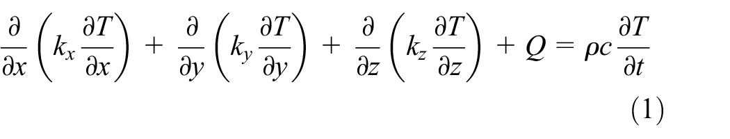
where
There are three boundary conditions:
S1: given temperature of the boundary

S2: given heat flux distribution of the boundary
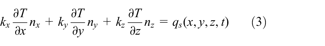
S3: given heat convection of the boundary

where
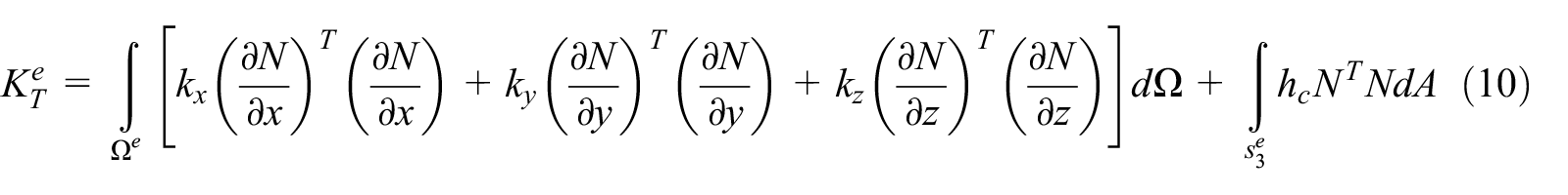
When using finite elements to calculate the temperature field of welding, the object

where

The following equation is obtained after solving

where


where
The solution of the equation for the welding stress and the strain field is considered as a nonlinear transient problem of the material. Therefore, four fundamental relations are obeyed when thermal elasto-plastic analysis is performed: 10
The relation between strain and displacement (compatibility condition);
The relation between stress and strain (constitutive relation);
Equilibrium condition;
Response to boundary conditions.
For thermal elasto-plastic analysis, the following assumptions are given: the yield strength of material obeys the (von Mises) yield criterion; behavior in the plastic zone obeys the plastic flow rule and the hardening rule; the elastic strain and the plastic strain cannot be separated; and temperature-related mechanical properties, stress, and strain vary linearly within a small time increment.
Thermal stress is caused by thermal expansion due to the temperature difference in the object, so that the relevant physical equations are the following

After converting to the index form, we obtain
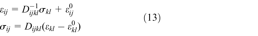
where
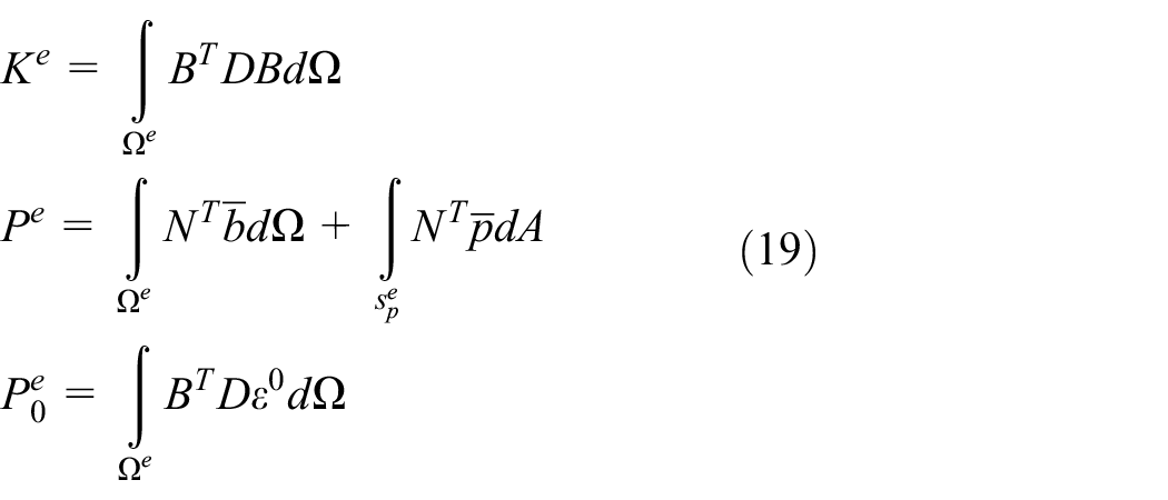
Using finite elements for the analysis and solution, the object is dispersed into the elements to obtain the following functional relationship between the mechanical parameters and joint displacement


Where N, B, D, and S represent the shape function, the geometric matrix, the elastic coefficient matrix, and the stress matrix of element, respectively, and
Virtual displacement and virtual strain can be obtained by solving the variation

The following equations can be obtained using the principle of virtual work

where
and
Welding deformation
Welding is a local heating process. Due to uneven heating and plastic deformation after the cooling of the weldment, welding stress and deformation occur. The welding deformation includes the transient deformation during welding and the residual deformation at room temperature (the residual deformation is also known as the post-welding distortion). Every structural member can deform due to the uneven heating in each direction and generate longitudinal shrinkage, lateral deformation, bending, angular deformation, buckling distortion, and so on. These distortions always co-exist and affect each other. Moreover, the assembly sequence of the welding parts, their rigidity and dimensions, the distribution of weld joint, and the welding process can affect the welding deformation.
Heat source model for welding
The heat source model simulating the distribution of heat flow during welding is a fundamental condition for carrying out a simulation of the welding process. As a local concentrated heat input, the heat source results in an uneven temperature field with a very large gradient on the structural members, leading to high welding stress and deformation. Different welding methods can generate different heat flow distributions, so that the heat source input model shall be selected on the case-by-case basis. During the development of the welding analysis methodology, many new models have emerged, such as the Gaussian, hemisphere, ellipsoid, and double ellipsoid heat source models. 11 The Gaussian model is applicable to the normal welding method, and even if the material performance is nonlinear, the accuracy of analysis can be improved. However, for welding with high arc impact, the hemisphere, ellipsoid, or double ellipsoid model shall be used in order to improve the accuracy.
The welding process can be considered as the heat source movement on the structural member. For the simulation, the zone around the weld joint shall be meshed very well. To increase the computational efficiency and reduce the dependence on the computer hardware, segmented Gaussian, Gaussian string and segmented ellipsoid heat source models have been developed. When the heat source is segmented for the analysis, the computational cost can be reduced by 10 times or more without compromising the accuracy. A segmented heat source refers to a long weld joint that is meshed into many sections. Each section is heated in the welding sequence to convert the movement of the point heat source into that of a segmented heat source and to reduce the computational cost. In this case, the computational accuracy can be increased by increasing the number of the segments. The string heat source is based on the segmented heat source and loads the point heat source onto the node of a discrete unit in each section to improve the flexibility of this method. Generally, point and segmented heat source models of heat movement must be realized using subroutines, whereas the string heat source can be realized by selecting nodes and increasing the analysis steps. Literature11,12 reported numerical simulations using a Gaussian heat source, a Gaussian segmented heat source, and a Gaussian segmented string heat source in the heat movement and compared the obtained results. Due to the highest computational efficiency, the segmented heat source is preferred for modeling, but the zone around weld joint must be meshed well in order for this method to converge. The string heat source has high application flexibility, so it can be used to simulate the irregular weld joint and does not require fine meshes. The Gaussian heat source in the movement has the highest accuracy, but it requires the use of fine meshes and incurs a high computational cost.
Numerical simulation and analysis for welding based on Abaqus
Welding simulation and analysis process
The indirect method of thermal elasto-plastic analysis is used in this article for welding simulation of a crane girder. First, heat conduction is analyzed to obtain the temperature field of the welding process. Then, the obtained temperature field is used to analyze the thermal stress and obtain the welding stress and strain. The analysis algorithm is shown in Figure 1.

Algorithm for numerical analysis of welding.
When heat conduction is used to analyze the temperature field, heat elements must be adopted. For a three-dimensional (3D) model, the 3D solid element DC3D8 or plate elements DS3 and DS4 can be used. When a discrete model is used, since the temperature around weld joint varies greatly, the zone must be meshed well (small mesh size). Due to the small temperature variation, it is not necessary to finely mesh the zone far from the weld joint in order to ensure the convergence and efficiency of the computation. The density, thermal conductivity, and specific heat of the material must be defined with boundary conditions of thermal radiation and thermal convection.
In Abaqus, the heat source can be loaded either by in-element heat generation or using a subroutine. The in-element heat generation loads the heat source onto the node of the weld joint, and heat is input for the different nodes in each analysis step to enable those nodes to transfer heat to other nodes and obtain a variational temperature field. In the subroutine approach, a user subroutine dflux is created that determines the center of the heat source by analyzing the time parameter TIME(2). The heat flux of the heat source is calculated according to the flux function FLUX(1), and the subroutine is written in Fortran and can be called by saving for. The string heat source is used in this article, so that in-element heat generation is adopted.
For analysis of thermal stress, 3D solid elements and plate elements S3 or S4 shall be used for a 3D model. The density, elasticity modulus, Poisson’s ratio, plastic stress and strain, and coefficient of thermal expansion are defined as material properties. The temperature field analysis result file .odb is input as a predefined temperature field for thermal stress analysis so that the stress and strain of the structure in this temperature field can be analyzed.
Numerical simulation for welding deformation of girder cover and web
The Abaqus software is used to perform the numerical simulations for girder welding on a 50/10-t overhead crane (shown in Figure 2) in order to obtain the welding deformation of the girder.13–15 Therefore, the blanking curve of the girder web can be better controlled. The welding between the girder web and the upper and lower covers can cause a deflection over the girder span, the welding between the web and ribs can cause a lateral deformation of the girder, and the welding between the covers and ribs can cause a surface deflection of the covers. To reduce the welding deformation, first the welding of the web with steel angles and of the covers with the ribs is carried out, followed by the welding of the covers with the web to form a π-shaped girder. The welding of the lower cover is performed last. A clamping fixture is used to ensure that the web plate and the top/bottom plate are tightly fit for positioning welding. In this article, the welding deformation of long weld joints on the girder covers and web was simulated first.

Model of a 50/10-t overhead crane: (a) illustration of girder structure and (b) illustration of section attributes.
The parameters of the research object are as follows:
Effective length of the girder: 31.5 m.
Gauge of trolley: 3580 mm.
H, the spacing between top and bottom plate: 1700 mm.
B1, width of the plate: 650 mm.
B2, the spacing between webs: 590 mm.
T11/T12, the thickness of top/bottom plate: 24 mm.
T21/T22, the thickness of left/right web: 6 mm.
Spacing between large stiffening ribs: 1200–2750 mm.
Spacing between small stiffening ribs: 400–500 mm.
Modeling
The crane girder is a large structural component, and a large number of computations are required for the numerical simulation. To increase the computational efficiency, the following assumptions are made to simplify the model: upper and lower covers, webs, and ribs are flat and straight without internal stress; no external load or constraint is applied during the welding; and the solid-state phase change during the welding is ignored.
Moreover, since the girder structure is symmetrical in both longitudinal and transverse directions and the welding is carried out simultaneously in four symmetrical parts, only a quarter of the girder structure was analyzed. The steel angles have less influence on the deflection of girder and therefore are ignored. Large variation of the welding temperature and the corresponding change of the thermophysical properties of the material can influence the calculation result. Therefore, a table of listed thermophysical properties is created. The girder is made of the Q235 mild steel, and its mechanical properties are listed in Table 1.
Mechanical properties of Q235.

3D plate elements are used to mesh the girder, and a plurality of element points are set with flexible temperature along the thickness of each plate node so that the temperature can vary not only with the reference plane of the shell but also with the thickness. The calculation efficiency of the plate elements is much higher than that of the solid elements, so the computational cost of the use of 3D plate elements for analysis is lower. Elements DS4 and DS3 are used for heat transfer analysis, and elements S3 and S4 are used for thermal stress analysis. Since a string heat source was used to simulate the welding and the welding deformation is the focused of the present study, a coarse mesh with multiple segments can meet the necessary accuracy. If the meshes around the weld joint are dense and loose far away from the weld joint, higher accuracy can be obtained. However, this irregular meshing can easily cause the temperature at some nodes to be lower than absolute zero during the calculation of the temperature field, leading to the lack of convergence. This problem can be avoided by adopting the coarse mesh without compromising the accuracy. A quarter of the girder is taken for meshing and analysis, and the number of elements is 13,812, as shown in Figure 3. The x and z directions represent the span and the width of girder, respectively.

Finite element model of welding.
Temperature field calculation
Carbon dioxide arc welding is adopted with a current of 200 A, voltage of 20 V, welding speed of 6 mm/s, and heat input efficiency of 0.8. 11 The welding sequence for the crane girder can affect the welding deformation. The commonly used procedure shown in Figure 4 is to first weld the upper cover, followed by the web, ribs, and steel angles to form a π-shaped girder and then to weld the lower cover. For the welding of a long joint, the cover and ribs are welded first; next, a fillet joint is formed from the center to both ends; and then, the second fillet joint is formed from both ends to the center. Finally, the lower cover is welded from the center to both ends.

Welding sequence.
Selection and loading of heat source
The covers and ribs of the girder were welded together via T-joints for which the heat flux cannot be reasonably described by the Gaussian function, so the Gaussian string heat source was adopted. The Gaussian heat source is a constant point heat source, the heat flux of which can be expressed by


where
The integrated heat input per unit time from the Gaussian heat source is

This shows that the required action time for each segmented heat source simply depends on the energy concentration factor and the welding speed. If there are N + 1 nodes on joint a, this means that joint a is meshed into N segments, and thus, the heat input per time unit on this joint is as follows

This heat input can be applied on each node except for the nodes at both ends, the heat input of which is equal to
Each of the joints between the upper cover and the web of the girder is divided into five segments; each of the joints between the web and the lower cover is divided into four segments; and each miter joint is considered as one segment. A total of 16 load steps are created. Each of the first 15 steps is used for analyzing a joint segment in order to complete the welding from the upper and lower covers to the web. Cooling is performed in the final step. Each load step is allocated with a node in a joint segment with the heat source applied, and the time for the load is defined as 1.7 s. The selection of the nodes and the execution sequence of the load steps can enable the segmented heat source to move.
Setting of boundary conditions
The boundary conditions for the welding process are radiation and convection. It is difficult to obtain the convection coefficient and the radiation coefficient that vary with the temperature. However, the overall heat transfer coefficient is known, and therefore, the overall heat transfer coefficient is set as the convection coefficient. The initial temperature is set as 20°C, and the latent heat of phase change is not considered.
Calculation result of temperature field
An automatic time step was used for calculation, which means a small step corresponds to a large temperature variation during the welding and a large step corresponds to a small temperature variation during cooling. This setting can save calculation time and ensure convergence.
In this work, only the fillet joints from the upper and lower covers to the ribs of the girder are analyzed to obtain the flexural deflection of the girder after the welding. The calculation for the temperature field of the 3D plate elements of the girder is shown in Figures 5–7.

Temperature field of first weld joint.
Temperature field of third weld joint.

Temperature field of 12th weld joint.
It can be seen that the welding temperature of the girder reaches 799°C with the heat flux of 8.4 × 10³, while the temperature changes with the movement of the heat source.
Calculation of strain field
Once the stress field is obtained, the indirect method is used to analyze the stress and strain fields of the girder. The elements are changed to structural elements S3 and S4, and nonlinear analysis steps are created with the automatic step size. The initial temperature in the field is set as 20°C, the temperature field result file is read and the initial and final analysis steps are set for reading. During the calculation, the temperature field result of each analysis step is obtained to calculate the stress and the strain.
The mechanical properties of the material are defined based on the temperature as well as on the symmetry plane constraint in the middle of the span and the width of the girder. A fully constrained node is also defined to avoid the rigid movement of the girder (Figure 8).

Welding constraints.
The obtained strain diagram plots in y direction after analysis are shown in Figures 9 and 10.

Strain plot in y direction of the girder.

Strain plot along the web.
As shown in the figures, the maximum deformation occurs at the extension part of the girder because this part is not constrained by the web (free deformation occurs after welding due to the absence of boundary conditions). The extension part of the upper cover tilts upward while the extension part of the lower cover tilts downward. For flexural deflection of the girder welding, only the deformation on the joint between the upper cover and the web in the y direction is considered. It can be seen that the girder deflects downward, and the maximum downward deflection of the upper edge of the web is 1.686 mm, occurring in the middle of the span.
To obtain the deflection curve of the girder after welding, we select some discrete points along the joint between the upper cover and the web and take the rightmost point as the origin, the distance from this point as the x-axis, and the deformation in the y direction as the y-axis. The maximum deflection is 1.686 mm, as shown in Figure 11. Because two main joints are arranged in the upper and lower parts of the girder, respectively, (the upper joints are double-sided type and the lower joints are single-sided type) and they cancel each other out, the welding deformation is small.

Deformation curve for upper web after girder welding.
Numerical simulation for welding of web and steel angle
The welding of the web and steel angle could result in a flexural deflection of the web, and it therefore must be finished before assembly. The finite element model is shown in Figure 12. Provided two weld joints are formed simultaneously, each joint is divided into five segments and the segmented string heat source in the movement is adopted.
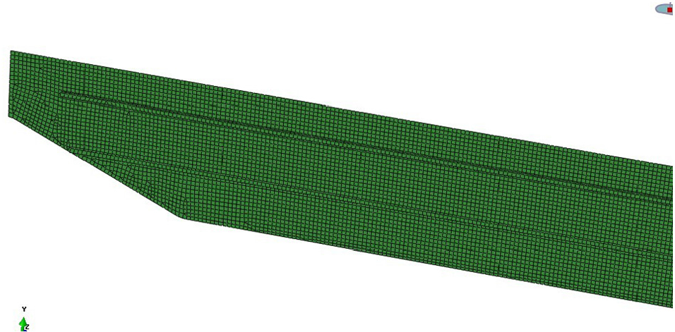
Finite element model of welding for web and steel angle.
The obtained temperature field analysis results for the welding are shown in Figures 13 and 14.

Temperature field during welding of web and steel angle.
Temperature field after cooling of welding of web and steel angle.
Half of the web is used for analysis, and therefore, a symmetry constraint is set at the midspan. Since the web is laid on a platform for welding, a constraint in the z direction for the web is set. To avoid rigid movement of the web, a constraint in the y direction at midspan is set. The web deformation during welding is mainly analyzed, as shown in Figure 15. The web deflects downward during the welding with the maximum deflection of 3.71 mm. Because the joint on the upper steel angle is far from the centroid of the cross section but the joint on the lower steel angle is close to the centroid, the welding deformation on the upper steel angle is larger, resulting in the web deforming downward.

Web deformation during welding of steel angle.
Numerical simulation for welding deformation of ribs
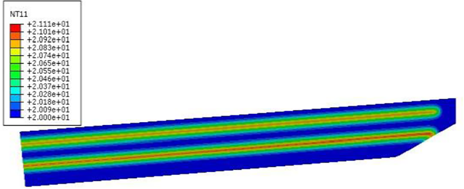
For the welding of ribs, the upper cover is welded with the ribs separately, and the centroid is close to the cover (the joint is close to the centroid), so the small deflection of the cover during welding can be ignored. After the welding between the cover and the web is finished, the welding of the web with the ribs is started. The deformation caused by the welding between the web and the ribs is mainly analyzed via the model shown in Figure 2. To simplify the analysis, it is assumed that all ribs are welded simultaneously and each weld joint is heated up evenly. The temperature field analysis results are shown in Figures 16 and 17.

Temperature field during welding ribs.

Temperature field after cooling of welding ribs.
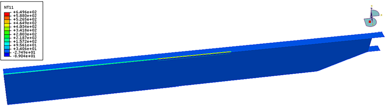
The same boundary conditions as those described in section “Numerical simulation for welding deformation of girder cover and web” are adopted, and the constraint of the web in the z direction is removed. The deformation plots for the welding of the web and ribs are shown in Figures 18 and 19, and only the flexural deflection of the web is considered here. It can be seen that the web deflects downward after the welding and the deflection at midspan is 3.33 mm. For the welding of the ribs, small ribs are arranged close to the upper part of the web so that the upper part of the web displays a larger shrinkage deformation, resulting in downward deflection of the web.

Overall strain plot.

Strain plot for web.
Results and discussion
1. Based on the welding simulation of the upper and lower covers and the web, the girder deflects downward by 1.686 mm (Table 2). Based on the welding simulation of the web and steel angles, the downward deflection is 3.71 mm. Based on the welding simulation of the web and ribs, the downward deflection is 3.33 mm.
Comparison of numerical simulation results with experimentally obtained welding deformations.

According to the above analysis, the numerical simulation result for the welding deformation of girder is roughly the same as the experimental result obtained in our previous research. 16 Therefore, the thermal elasto-plastic finite element analysis is feasible and reliable for use in modeling with 3D plate elements. Although simplifications such as the simplifications of model, heat source, material properties, and welding process are adopted for analysis, this kind of analysis has advantages of fast calculation (short calculation time) and high accuracy.
2. If the deformation caused by the interaction force between the parts is not considered during the welding process, the final welding deformation obtained as the sum of all individual deformations is
3. The camber of the crane girder is considered to compensate for the operation downwarping and thus can decrease the energy consumption of the trolley with improved operation performance.
In some studies, it was reported that there is no need to design the camber because the deformation can be decreased by improving the crane’s stiffness. However, currently, the structure of crane tends to be stable with less room for improvement and limited material selections, and the changes of the crane structure are constrained by design and manufacturing costs. However, it is undesirable to enhance the stiffness solely by increasing the weight of the bridge because of the increased costs. Therefore, it is necessary and feasible to prefabricate the camber of the girder. To achieve this goal, thermal elasto-plastic analysis is used together with the Abaqus software to analyze the welding. Gaussian movable heat sources model with a reasonable number of segments is proposed for welding simulation. The simulation results show that the camber should be increased by 8.7 mm during the web cutting to offset the welding deformation of the girder. Therefore, elucidation of the laws governing the welding deformation can better guide web cutting; obtain better camber curve; and ensure smooth, safe, and energy-saving operation of the traveling trolley.
Footnotes
Acknowledgements
The authors acknowledge the Editor.
Handling Editor: Seung-Bok Choi
Declaration of conflicting interests
The author(s) declared no potential conflicts of interest with respect to the research, authorship, and/or publication of this article.
Funding
The author(s) disclosed receipt of the following financial support for the research, authorship, and/or publication of this article: This work was supported by the National Key Research and Development Program of China (2017YFF0209800 and 2017YFF0209804). The support was gratefully acknowledged.