
Abstract
The crane is a mechanical device used to move materials in modern production. It plays a very important role in the national economy by greatly reducing labor intensity, improving production efficiency, and promoting social development as an indispensable auxiliary tool. The energy consumption of a crane is very large. There are several factors influencing energy loss, especially the camber of the girder, which is thought to compensate for the operation downwarping and, thus, decrease the energy consumption of trolleys with improved operation performance. Thus, analysis and calculation of the camber for crane girder is necessary in order to design a reasonable camber curve for the compensation of girder deformation by self-weight and loading. In this study, the deformation source is analyzed, and an estimation model of camber for the bridge crane is proposed. The camber is theoretically discussed and estimated with respect to self-weight, wheel pressure, and welding. As a result, the optimal corresponding camber curve that could compensate the deformations by self-weight, wheel pressure, and welding were obtained. Calculation of the energy consumption of the trolley is also presented. By using a 50-t, 31.5-m double girder crane as the research object, calculation of its camber and design of the reasonable camber curve for energy-saving were analyzed and demonstrated. These results may provide a design reference for girder camber curve and validation of the effectiveness of crane simulation modeling.
Introduction
The crane is a mechanical device used to move materials in modern production. It plays a very important role in the national economy by greatly reducing labor intensity, improving production efficiency, and promoting social development as an indispensable auxiliary. 1 The energy consumption of the crane is very large. 2 There are several factors influencing energy loss, especially the girder. 3 When the bridge crane is working, wheels of the trolley will press on the bridge and generate a downward bend. If the deflection is too large, “climbing” will occur and the driving force required will increase. The deflection can negatively impact the performance of the crane trolley. 4 Thus, it is necessary to analyze and calculate the camber for the crane girder in order to design a reasonable camber to compensate for girder deflection by its weight and loading, which can decrease the deflection and energy loss.
The camber of the crane girder is thought to compensate for the operation downwarping and, thus, may decrease the energy consumption of the trolley with improved operation performance. 5 Some studies have reported that there is no need to design the camber as the deformation can be reduced by improving the crane’s stiffness. Presently, the structure of the crane is stable with less space to improve; limited material selections and the changes of the crane structure are constrained by design and manufacturing costs. However, it is undesirable to increase the bridge’s weight to enhance the stiffness because of increased costs. Therefore, it is necessary to prefabricate the camber of the girder. 6 At present, camber curve of crane girder plate is widely adopted.7,8 While welding, self-weight, and the loading, all can cause deformation, it is difficult to obtain an ideal camber curve. Fu Rongbo discussed the basic principles of camber curve on the girder and introduced the camber specified by domestic and international technical standards. Furthermore, various forms of special pre-change curve were proposed. 9 In literature, 3 the advantages and disadvantages of popular camber curve (parabola, sinusoidal, three-fold) were discussed and a new camber was proposed. Most studies focus on the camber curve to ensure that displacement remains zero (0) for trolley at any position on the girder. However, it is necessary to overcome the climbing resistance when the trolley moves on the bending track. The climbing resistance is closely related to the slope of where the trolley moves. To eliminate the climbing resistance, the ideal camber curve should ensure that the slope remains zero (0) for trolley at any position on the girder. Besides, to determine an ideal camber curve after welding, certain precambers of girder web cutting are needed in order to compensate for the deflection by self-weight, hoisting load, welding, and so on.
This study was carried out in order to obtain a theoretical camber of the bridge crane. In the second section, the girder web cutting for the bridge crane was analyzed and the basic estimation mathematical model is proposed. In section “Theoretical analysis of camber curve for the crane girder,” the camber curve for the crane girder is theoretically analyzed and discussed in detail under self-weight, wheel pressure, and welding. In section “Calculation of energy consumption for the trolley,” energy consumption of the trolley is discussed. In section “Case study,” a study is used to demonstrate how the camber is calculated, and the reasonable camber curve is designed. Finally, conclusions are summarized.
Camber estimation of girder web cutting for the bridge crane
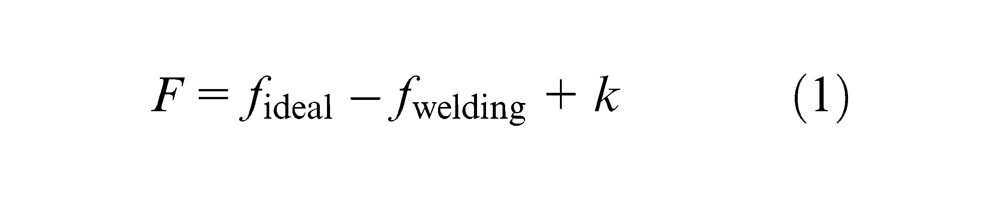
To determine an ideal camber curve after welding, certain precambers of girder web cutting are needed in order to compensate for the deflection by self-weight, hoisting load, and welding. The value of the span camber, F, can be calculated by using the formulas (1) and (2)
Theoretical analysis of camber curve for the crane girder
Mathematical optimization model
To reduce the running energy loss of the crane trolley, the ideal camber curve should be designed so that the trolley can keep a horizontal movement anywhere, thereby eliminating climbing resistance. The ideal curve needs to compensate for the downwarping caused by self-weight, wheel pressure, and deformation by welding deformation.
Compensation for downwarping by wheel pressure
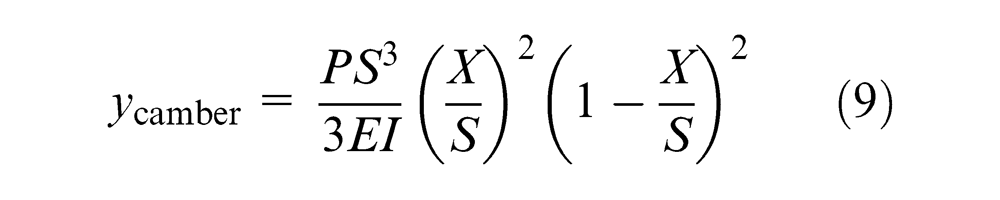
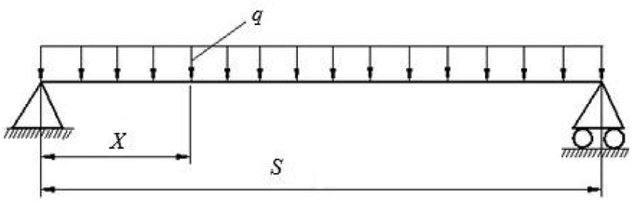
As shown in Figure 1, the bridge crane may be considered a simply supported beam; it is necessary to overcome the climbing resistance when the trolley moves on the bending track. The climbing resistance is closely related to the slope of where the trolley moves. To eliminate climbing resistance, the ideal camber curve should ensure that the slope remains at zero (0) for any position on the girder 10
where
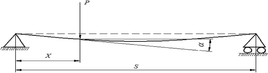
Girder illustration under wheel pressure (P denotes the load, X denotes the distance between loading position to left end, S denotes the span length and
At certain position X, the downwarping inclination
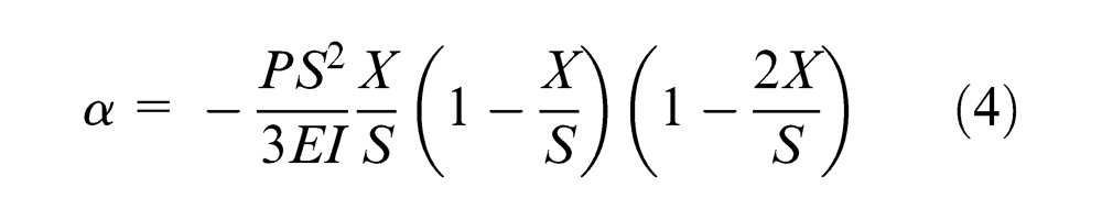
Because
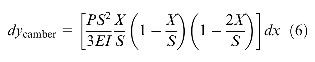
After integral solution of formula (6), the camber curve can be expressed as
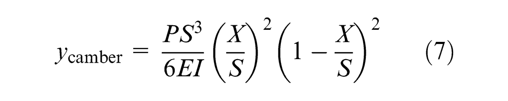
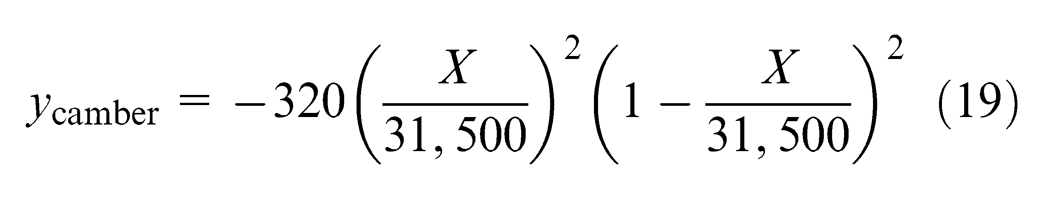
When
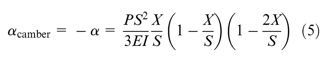
As for crane girder without camber, the maximum downwarping occurs at the middle of girder (
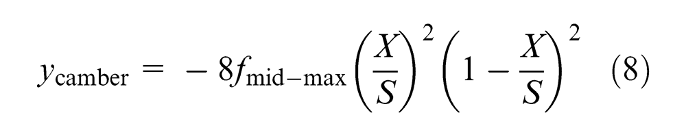
From formula (7), it can be concluded that the maximum camber occurs at the middle span (middle of the girder), which is half of the maximum downwarping of girder without camber.
In some studies, the precamber of the ideal girder curve is considered to be equal to the downwarping for the trolley at any position; that is, the trolley remains at a horizontal line during movement. Therefore, the camber curve of the simple beam can be expressed as
The value of
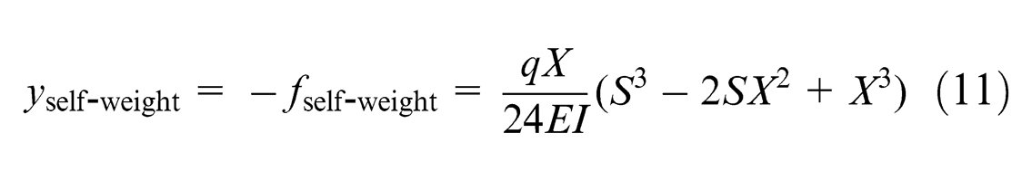
Compensation for downwarping by self-weight
Due to long length and small cross-sectional area of crane girder, self-weight of crane girder will cause the girder downwarping. The force of girder self-weight can be considered as uniform load and both ends as supporters, as shown in Figure 2.
Girder illustration under self-weight.
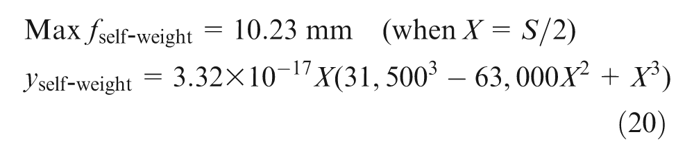
To compensate for the downwarping by self-weight, the girder should be designed with the camber conformed to downwarping curve. The downwarping by self-weight can be calculated by formula (10)
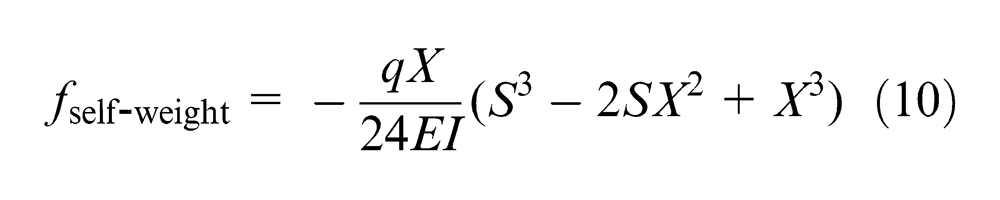
where q denotes the weight per length unit, S denotes the girder span, and I denotes the inertia moment of girder section.
Camber compensation for downwarping by self-weight can be expressed as
a compensation for welding deformation. 11
Welding residual stress and deformation of the girder after welding occur unavoidably due to instantaneous high temperature and cooling, which negatively impact the crane camber. Theoretical welding deformation calculations of the box beam must be based on the following assumptions: 12
Material itself without original stress and deformation, ignoring the internal stress and deformation by cutting.
No loadings or constraints without consideration for the impact of environmental temperature and self-weight.
Maintenance of certain welding methods and parameters during girder welding.
In actual production, these assumptions are not fully fulfilled; however, the calculation of welding deformation can reflect the actual welding deformation discipline of the crane girder.
Welding deformations of the box girder include the girder deflection by longitudinal and transverse welding seam shrink. According to welding shrink methodology, deformations can be approximately calculated by formulas (12) and (13)
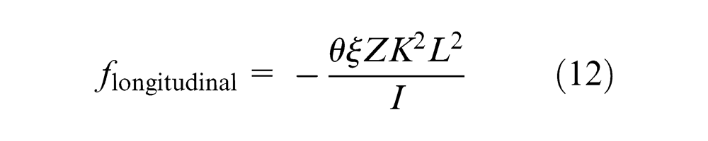
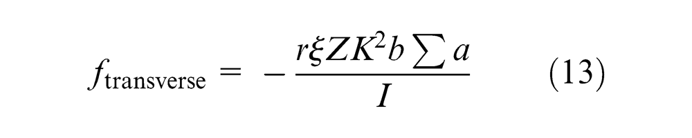
where
If the welding seam conforms to d-isometric and symmetrical distributions, the deformation of the transverse welding seam can be calculated by formula (14)
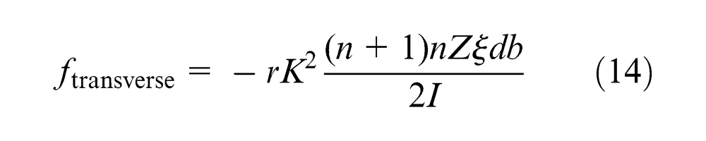
where d denotes ribs spacing and n denotes the number of rib spaces on half span.
Usually, girder welding is composed of several processes. The deformation of each process is needed to make calculations based on their section properties, welding angles, welding methods, and so on. Then
The direction of welding deformation is determined by the distance, Z, from the welding seam to the axis. If the welding seam is on top of the axis, then Z is positive; otherwise, Z is negative, which results in camber deformation.
Permanent deformation after usage13,14
Permanent downwarping of the crane occurs after long-term usage. With the increase of service life, the camber will gradually disappear, resulting in increased downwarping or even discarding. This deformation may due to the following:
Residual stress. The manufacturing and assembly processes produce residual stress, causing downwarping of the girder during crane use.
Fatigue. Alternating stress may be generated when the crane is lifting, transporting, or unloading, especially under high-level working conditions, such as by frequent use, overloading, and unreasonable use. Under alternating stress and fatigue, further downwarping will occur.
The downwarping produced during usage should be measured regularly. Detection methods include drawing wire and level detection with high continence and accuracy. If the downwarping is large enough to exceed the standard level, the camber needs to be corrected, usually with a flame or pre-stress straightening method. When the downwarping reaches a certain level, the crane should be scrapped.
Calculation of energy consumption for the trolley
When the crane is working, downwarping of girder will occur, forcing the trolley to overcome frictional and climbing resistance. Climbing resistance is due to the inclination between moving direction and horizontal line, 15 which can be calculated according to formula (16)
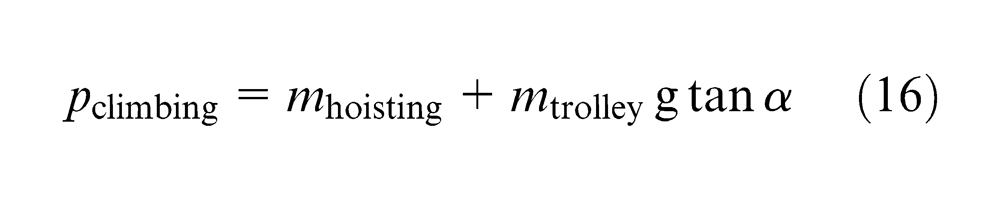
where
Frictional resistance
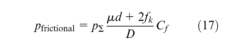
where
The crane’s energy consumption, E, mainly includes climbing energy consumption,
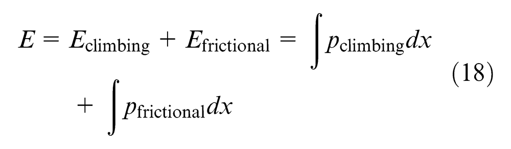
In actual operation, uphill or downhill energy cannot be avoided. Uphill operations consume energy, while downhill operations cannot recycle energy. Therefore, only climbing energy consumption for uphill operations are considered. On the other hand, the movement direction of the trolley has no effect on the frictional energy, which only considers the energy consumption for horizontal moving.
Case study
Consider a bridge crane used in a practical project as the research object, which is a 50-t, 31.5-m double girder crane used widely at home and abroad and characterized by simple design, good manufacturability, stable structure, and so on.
The girder is mainly composed of top plates, big stiffening ribs, small stiffening ribs, horizontal angle irons, bottom plates, left web, and right web as shown in Figure 3. The structural and sectional attributes are as follows and as shown in Figure 4.
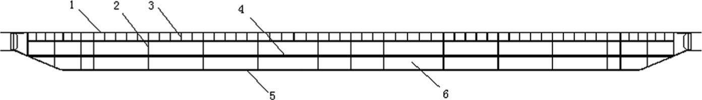
Structural illustration of girder: (1) top plate, (2) big stiffening ribs, (3) small stiffening ribs, (4) horizontal angle iron, (5) bottom plate, and (6) webs.
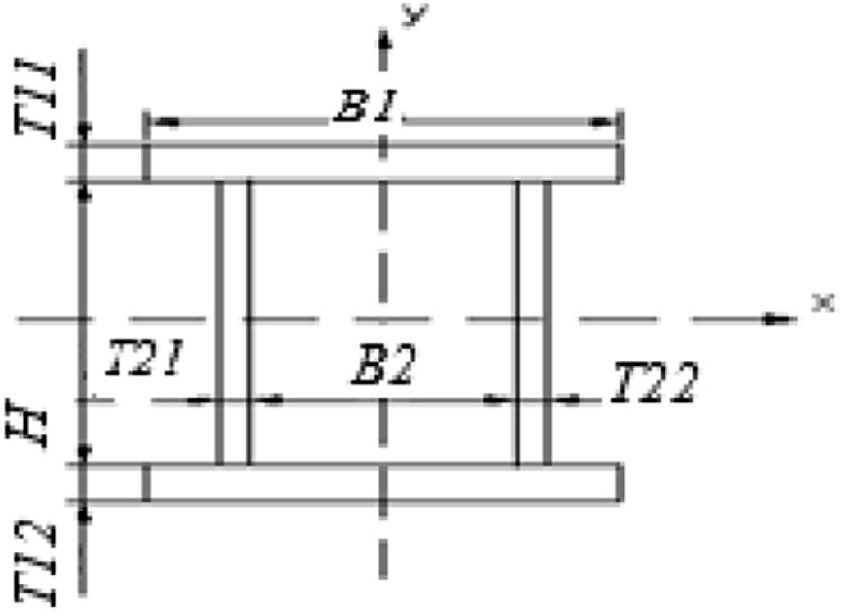
Section attributes illustration.
Parameters are as follows:
Rated load: 50 t;
Effective length of the girder: 31.5 m;
Gauge of trolley: 3580 mm;
Weight of total girder: 37.8 t (beam: 14.833 t; end girder: 4.067 t);
Weight of trolley: 15.4 t;
H, the spacing between top and bottom plates: 1700 mm;
B1, width of the plate: 650 mm;
B2, the spacing between webs: 590 mm;
T11/T12, the thickness of top/bottom plate: 24 mm;
T21/T22, the thickness of left/right web: 6 mm;
The spacing between big stiffening ribs: 1200 mm, 2750 mm
The spacing between small stiffening ribs: 400 mm, 550 mm;
Material: ordinary carbon steel Q235.
According to the GBT 3811-2008 “Crane design standard,” the working level of the trolley is M5, and the working level of the cart is M6. 15
The following calculations are based on the above theoretical analysis:
Theoretical calculation of maximum downwarping by wheel pressure at the middle of girder: Because
So
Here,
According to formulas (10) and (11)
Welding first involves π-beam welding and then plate welding, including welding of webs, angle steel, plates, stiffening ribs, webs, and stiffening ribs, as well as plates and webs.
The welding of webs and up-angle steel occurs along the single-sided longitudinal welding seam.
Because
The welding of webs and down-angle steel also occurs along the single-sided longitudinal welding seam.
Because
The welding of top plates and stiffening ribs occurs along the double-sided transverse welding seam. When welding stiffening ribs, top plates and stiffening ribs are welded separately since the centroid is near the plate,
The welding of webs and stiffening ribs occurs along the double-sided transverse welding seam. The transverse welding seam used by big stiffening ribs is x-axis symmetrical, and can be ignored, while the transverse welding seam used by the welding of small stiffening ribs and webs is near the top plate, and deformation will occur. Because
When assembling plates with webs, the welding seam of top plates and webs use double-sided fillet welding seams. Because
The welding seams of the down-plate plates and webs are single-sided fillet welding seams.
Because
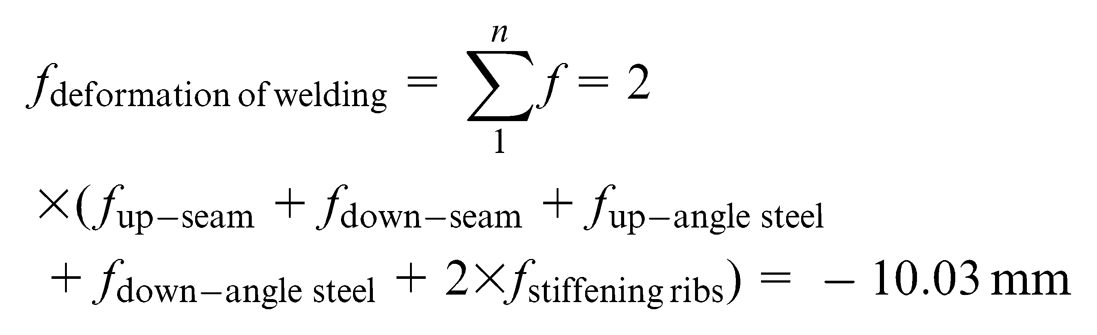
The total deformation can be calculated as follows: An appropriate increase of web-cutting camber is required due to the deformation by welding
Conclusion
This research sought to determine an energy-saving camber curve of crane and to provide the design reference for the bridge crane. The theoretical analysis and design of the crane camber curve are proposed here. The main results of this study are summarized as follows: (1) The impact of camber ensuring the horizontal track of trolley and ensuring the horizontal movement direction of the trolley is analyzed. It is more reasonable and accurate to design the camber of girder ensuring horizontal movement direction of trolley as expressed in formula (8) for minimum energy cost, which is derived from formula (3). However, in previous researches on camber design, the camber of girder is usually considered equal to the displacement of girders at certain point. (2) The factors influencing the camber were analyzed, including self-weight, wheel pressure, and welding (not considered before in most studies). The deformation by self-weight, wheel pressure, and welding is discussed and calculated as well as the corresponding camber curve. (3) A 50-t, 31.5-m double girder crane used widely at home and abroad was used as the research objective. The camber needed to compensate the deformation by trolley wheel pressure and girder self-weight were calculated, as well as the deformation by welding.
This study may provide the design reference for girder camber curve and the validation proof for the effectiveness of crane simulation modeling.
Footnotes
Acknowledgements
The authors would acknowledge the Editor of “Proceedings of the Institution of Mechanical Engineers, Part B: Journal of Engineering Manufacture.”
Declaration of conflicting interests
The authors declare that there is no conflict of interests regarding the publication of this article.
Funding
This work was financially supported by National Foundation of General Administration of Quality Supervision and Inspection (2012QK178), Program of Science Foundation of General Administration of Quality Supervision and Inspection of Jiangsu Province (KJ103708) and “excellence plans-zijin star” Foundation of Nanjing University of Science. Also, the work is pre-research of the National Natural Science Foundation of China (research on energy-consumption modeling and methodology of energy-saving design for cranes).