
Abstract
Due to the special structure characteristics, the switching process control from pure electrical driving mode to compound driving mode of the single-shaft parallel hybrid powertrain has caught broad attentions from related researches. In this study, a novel mode transition control method based on model predictive control algorithm is proposed to regulate the starting and engaging processes into driveline of the engine via an automatic clutch. According to the system states evolution process, the system control commands, that is, the immediate output torques of the engine, the motor, and the clutch during the mode transition process, are determined online by the proposed model predictive control controller, which derives the optimal control sequences to minimize the defined objective function by adopting quadratic programming in the prediction horizon. To better demonstrate the efficacy of the proposed control method, a simulation analysis platform is built based on MATLAB/Simulink and AVL/Cruise. Simulation results show that the coordinated control method can effectively suppress the vehicle longitudinal jerk within the reasonable range and reduce the clutch wear loss during the mode transition process.
Introduction
Energy crisis and environmental pollution bring new challenges for traditional automotive industry. Hybrid electric vehicle (HEV), with the advantages of energy-saving, low-emission, and mature technology, has provided the most feasible solution to these two vital problems. HEV always has two or more power sources, and different combination of the power sources can form a variety of driving modes. The difference of torque responses between the engine and the motor will cause a large deviation between the actual torque and the target torque during the start-up and shut-down processes of the engine and the motor, followed by obvious interruption of the power transmission or fluctuations of outputting torques, resulting in a bad vehicle dynamic performance and an uncomfortable ride comfort. Therefore, an efficient torque coordination control algorithm is very important to improve the performance of HEV power system. 1
Related research has been a hot issue in the area of hybrid powertrain control. In most studies, the motor is used to realize torque compensation during the power switching process because of its fast torque response characteristics. Toyota hybrid system (THS), which adopts a power split device with planetary gear sets, is capable of calculating the output torque of the engine by a certain ratio of the motor torque.2,3 The compensation torque of the motor is determined by the torque difference before and after the power switch. This system can eliminate the torque fluctuations during the power switching process. F Zhu et al. 4 divided the mode transition process into several periods and designed a fuzzy proportional–integral–derivative (PID) controller to reduce the power switching time, restrain body impact degree, and achieve the smooth transition between different modes. J Zhang et al. used pseudo target speed and output torque of the engine to calculate the motor speed in continuously variable transmission (CVT) hybrid vehicles. In this way, the smooth transition between the pure electric driving mode and the engine driving mode was achieved. 5 K Koprubasi et al. viewed the power switching of HEV as switching control problems of hybrid system. The experimental results showed that the switching control based on hybrid system theory can effectively reduce the impact in the HEV power switching process. 6 Tong Yi et al. proposed a dynamic coordinated control strategy for engine dynamic torque estimation and motor torque compensation. Experimental results verified the effectiveness of the proposed control strategy. 7
In general, most researches choose the engine and the motor as control objects and use the motor to compensate the engine torque, and this entails higher standards for the dynamic performance of the motor. Meanwhile, the engine is still started by an integrated starter/generator (ISG) in these circumstances, but the role of the clutch during the mode switching process is neglected. Model predictive control (MPC), which is developed in the industrial practice, is a new kind of computer control algorithm. MPC is realized through strategies of multi-step tests, online rolling optimization of performance indices, and feedback correction. It can reduce the modeling errors and uncertainties of structure, parameters, and environment. As a result, it is suitable for the situations where accurate mathematical model is hard to establish. For its high robustness and good application effects, MPC has attracted wide attentions by engineers and has been successfully applied in the control systems of petroleum, chemical, electric power, mechanical, and electrical industries.8,9 The transient process like mode switching in hybrid power system is nonlinear, uncertain, and time-varying, thus it is very difficult to establish a precise analytical model for this certain process, while MPC algorithm can provide a good way to solve these problems. 10
This article describes the transition control problem from pure electrical driving mode to compound driving mode of a single-shaft parallel HEV. The structure and dynamics of the driving system are analyzed first, and then, the driving modes of the HEV are divided according to the characteristics of the engine and the motor. On this basis, a MPC controller, which includes the prediction model, the reference model, and the optimization objective function, is designed. The controller helps to realize real-time torque distributions of the engine, the motor, and the clutch during the process of mode switching. Simulation results show that the output torque of each power source obtained from the MPC controller can make the clutch linkage characteristics gentler and linear during the switching process, as well as reduce the vehicle longitudinal jerk and the sliding wear of clutch. Smooth mode switching and comfortable riding performance are finally achieved.
System modeling and control problem description
Structure of the driving system
In this article, the hybrid driving system is a single-shaft parallel configuration with an automated mechanical transmission (AMT), as shown in Figure 1. The main components of the structure are an engine, an automatic clutch, a permanent magnet synchronous motor, and an AMT. Considering that the clutch acts as a boundary, the driving system can be divided into two parts. The first part contains the engine, while the second part contains the traction motor and the remaining parts of the transmission system. The driving wheels are connected with the transmission system through a standard gearbox and a differential.
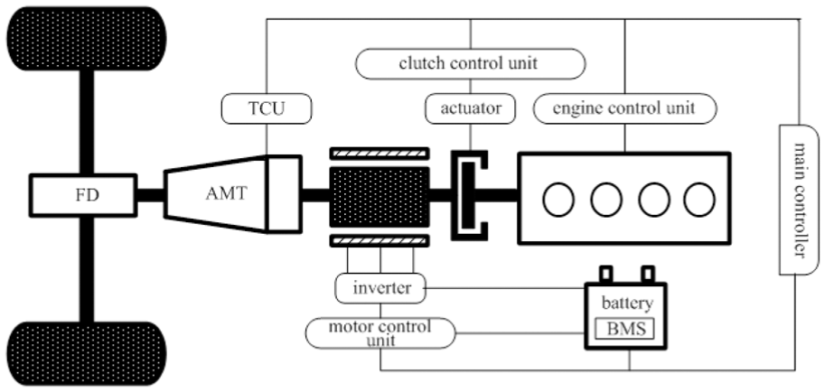
Hybrid drive system structure.
Analysis of the working modes
For single-shaft parallel configuration, HEV can work in a variety of modes, as shown in Figure 2, including pure electric driving mode (engine stops; AB), electric starting mode, engine driving mode (BC), compound driving mode (DE), driving while charging mode (CD), and regenerative braking mode (EF). It is noted that the demand power and the vehicle speed roughly corresponded for the general driving conditions.

Typical operating conditions and basic operation modes of a parallel HEV.
Hybrid vehicles can switch between different working modes by controlling the operation states of the engine, the motor, and the clutch. The dynamic characteristics of the clutch engagement process will have an important impact on the mode switching process. Notable friction torque fluctuations might appear in this period. The clutch engagement process will also have an influence on the driving performance and cause excessive wear to clutch. Therefore, the clutch can be used as the optimal control object in this study, and the dynamic engagement process of the clutch should be planned in order to realize the smooth mode transition. 11 The mode switching process from pure electric driving mode to compound driving mode in parallel HEVs includes the typical transient process of engine starting and the clutch engaging. This article will take the switching process of this certain mode as the control object and design a specific mode switching coordination controller.
System model
The equivalent model of a simplified coaxial parallel system with 2 degrees of freedom is depicted in Figure 3, where Tv, Tvh, TEM, Tc, and Te represent the vehicle load torque, the driving torque, the motor torque, the clutch torque, and the engine torque, respectively; ωw, ωEM, and ωe denote the wheel speed, the motor speed, and the engine speed, respectively. Ivh and Ie are the equivalent vehicle rotary inertia and the equivalent engine rotary inertia, respectively.

Simplified drive system structure.
The hybrid driving system shown in Figure 3 has the following dynamic equations

where ηo is the mechanical efficiency of the transmission system; i1 and io are the transmission (first gear) ratio and the main drive ratio, respectively. HEV is supposed to operate at low speed, and then ωω and ωEM are equal. The torque and the inertia of the power system are further equivalently converted to the two sides of the clutch, thus equation (1) can be further simplified as
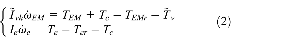
where
Clutch model
The clutch linkage process has great influence on the mode switching process. In order to achieve the clutch control, the clutch engagement process is divided into the following several periods: free travel period, clutch sliding period, speed synchronization period, and completely locked period. To meet the requirements for fast and accurate responses, a special automatic clutch is chosen, in which an automatic control system is added to the mechanical dry clutch. The automatic clutch mainly consists of a variety of sensors, electronic control unit (ECU), and clutch actuator. 12 The concrete structure of the clutch is shown in Figure 4. In actual control process, the driver’s torque demand transmitted to the clutch is converted to the electrical signal of the driving motor, thus the real-time performance of the clutch is better and the response is faster. Figure 5 is the load characteristics of the automatic clutch, which are obtained through experimental data.
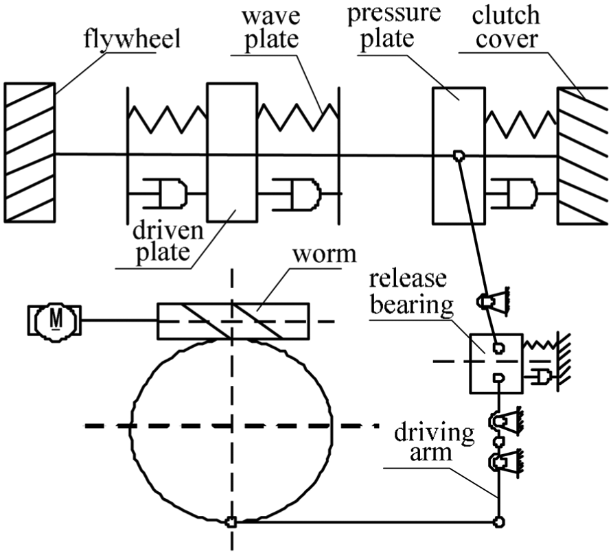
Structure of the automatic clutch.
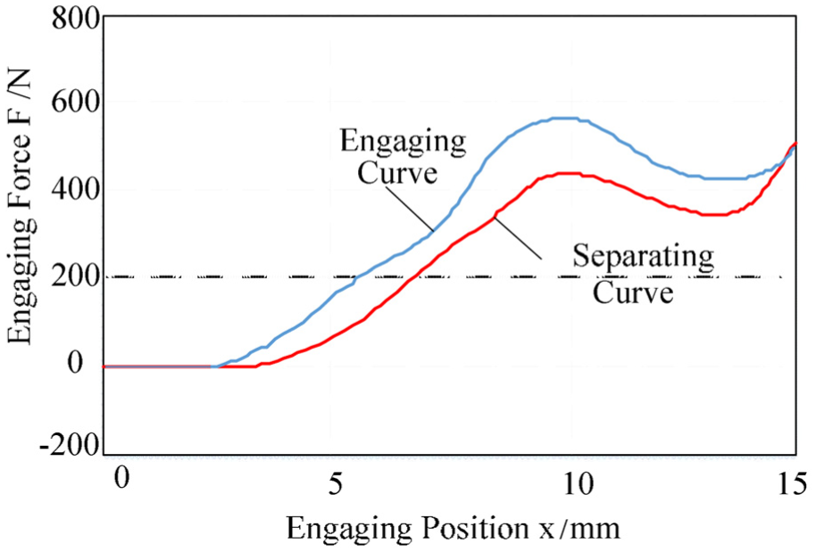
Load characteristic of the automatic clutch.
To represent the contact state of the driven clutch disks, a binary variable Δ is introduced. Δ = 0 means that both sides of the clutch are separated, while Δ = 1 indicates that the clutch is in the combination state, and this state can also be divided into two specific states, that is, the clutch contacting into sliding state and the complete locked state. The transmitted torque of the clutch in each state is given by

where Nc is the number of clutch disks, μc is the friction factor, Rc is the equivalent radius of clutch disks, and Fc is the clutch engagement pressure. In the locked state, the clutch torque is determined by the vehicle driving system and the clutch torque no longer affects the vehicle dynamics.
According to the system dynamic model and the different characteristics of the clutch torque, the state equations of the single-shaft parallel hybrid powertrain system from pure electric mode to compound driving mode are described in Table 1.
Description of pure electric driving mode to compound driving mode.

Torque coordination control problem
The torque coordination control problem is performed in the clutch linkage process during the mode switching from pure electric driving mode to compound driving mode. In this process, the friction torque has larger fluctuations. It will increase the longitudinal impact of the transmission system and then affect the riding comfort of passengers. In addition, the duration of the clutch linkage also increases. In other words, the synchronization speed between the driving disk and the driven disk can affect the mode switching time and cause different degrees of clutch wear. In view of the above two aspects, it is necessary to coordinate the conflicts between the output torques of the engine, the motor, and the clutch in the mode switching process, so as to ensure the smooth switching between different modes. 13 The effect of mode switching coordination control is characterized by the jerk and the slipping cost. The impact of jerk (J) is quantified by the derivative of the vehicle longitudinal acceleration versus time, and the slipping cost is the heat generated by the sliding process of clutch (ED). The calculation equations are shown as


where t1 and t2 refer to the starting and stopping time of the clutch sliding process, respectively; ω1 and ω2 refer to the speeds of the clutch driving and driven disks, respectively. Tc is the torque transferred by clutch.
Model predictive controller design
Based on MPC algorithm, this study proposes a model-switching coordination controller for mode transition. Detailed steps include establishing the discrete linear model of the clutch-oriented HEV in the mode switching process, calculating the system states and outputs in the prediction horizon, setting and solving the optimization targets, and finally applying the results to the controlled object. Specific control scheme is shown in Figure 6. 14
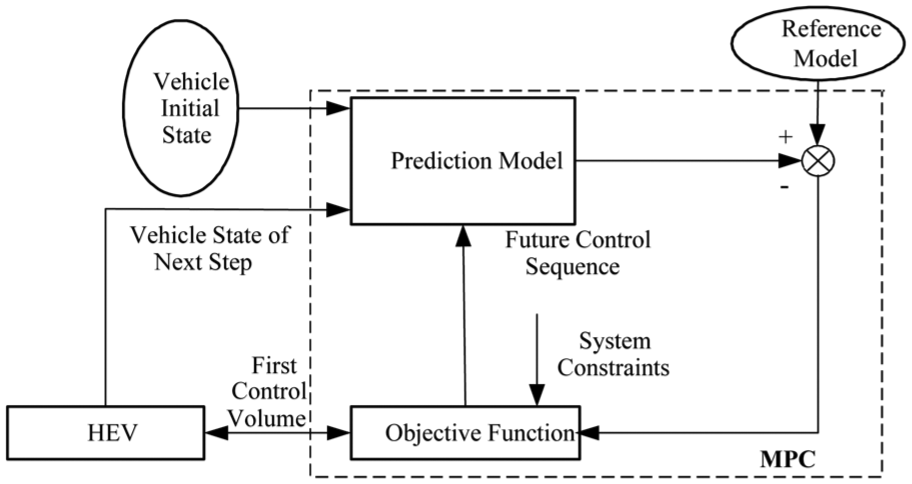
MPC coordinating control scheme.
Reference model
Since the clutch is locked after the mode switching process, the rotational speeds of the two shafts are synchronized. Therefore, the model in the mode that HEV is solely driven by the motor according to the required torque of the driver is selected as the reference model (clutch locked). The kinetic equation can be given by

where ωdem is the motor output speed of the reference model,
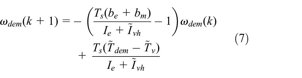
where ωdem(k) is the value of ωdem at sampling time k;
Prediction model
When the speed difference of two sides of the clutch is smaller than a certain threshold, the clutch gets into a sliding stage, which is also recognized as the specific intermediate process from the pure electrical mode to the compound driving mode. The kinetic equation of this process, as shown in equation (2), is assumed to be the predictive model of the MPC controller. By discretizing it at sampling time Ts, the following equation can be derived

Since the internal resistance torque of the engine and the motor can be described as

then, equation (8) can be further rewritten as

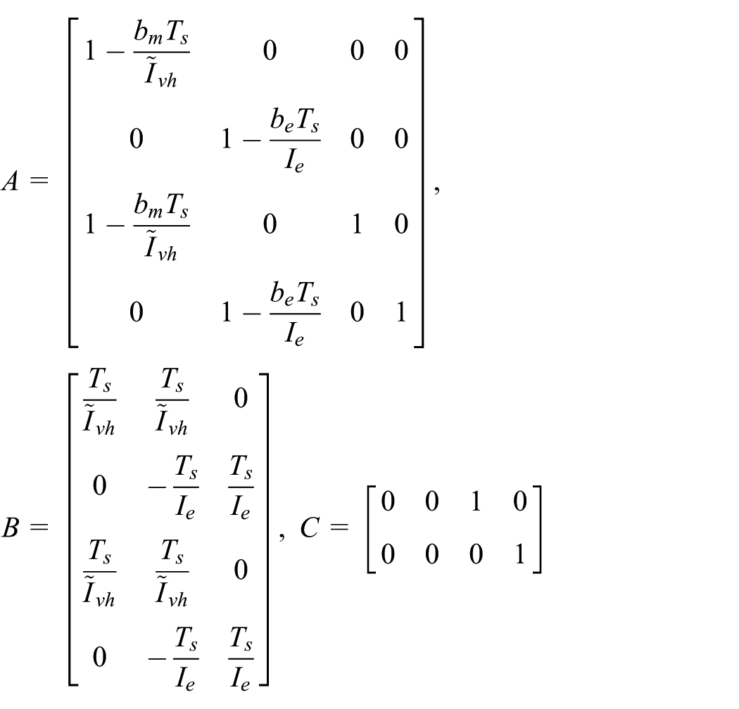
Then, the matrix form can be rewritten as

where

The model is further derived as

where
In order to simplify the execution of the later MPC algorithm program, the system state is further integrated as

where

By defining the prediction horizon as Np, the control horizon as Nc, then the system states and outputs in the prediction horizon can be derived by the following iterative process

The output vector in the next period is represented by

where

Optimization solution
Since the control increments of the system are still unknown, it is necessary to set some reasonable optimization goals. Then, the control sequences in the future control horizon can be calculated. To ensure the fast and stable responses of the system, the optimization of the system control variables and the variable deviations are added. Then, the objective function with constraints is set as follows
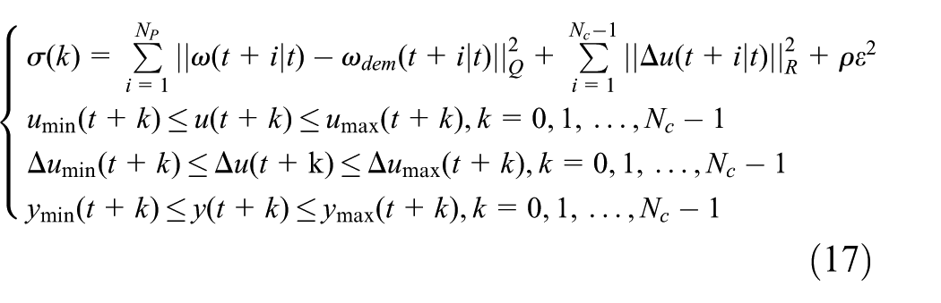
where Q and R are the weight matrix, ρ is the weight coefficient, ε (ε > 0) is the relaxation factor, which changes in a certain range for each sampling step. The optimization function adds precise constraints to the control increments and can strictly limit the transition of the control variables. The first term of the objective function reflects the tracking ability of the actual outputs to the reference signals. The second term represents the requirement for the steady change of the control variables. The additional factor of the last term is to ensure that the optimization function has a feasible solution at each sampling step. The optimization problems with constraints at each sampling step can then be transformed to a quadratic programming (QP) problem, which can be solved through “active-set” or “interior-point-convex” methods. “Active-set” or “interior-point-convex” methods are the algorithms for a QP problem. There are still many scholars in this field.16–18 After solving equation (13) iteratively in the prediction horizon, a series of control increment sequences can be obtained, as given by

The first increment of the sequence acts as the actual control increment to the controlled object

Under the feedback mechanism of MPC, the controller provides the current optimal results and continues to predict the optimization results in the next prediction horizon based on the updated system state information at the next sampling time. The above process is repeated until the completion of the entire control process.
Simulation results verification
For mode transition control of the single-shaft parallel HEV, an MPC control strategy is designed based on the torque instantaneous response characteristics of the engine and the motor. By compensating the response delay of the engine torque with the motor, this control strategy can reduce the torque fluctuation and impulse to a certain extent during the mode switching process, so a comfortable riding is achieved. The related results are verified by simulation analysis.
The simulation analysis platform is built based on MATLAB/Simulink and AVL/Cruise environment. To achieve the high accuracy of the vehicle dynamic model and quick-effective validation of coordinated control algorithm, the physical model of the driving system is built in AVL/Cruise. The controller and MPC algorithm are built in MATLAB/Simulink. The structure of the joint simulation platform is shown in Figure 7. The main parameters of the simulation test are shown in Table 2.

Joint simulation platform.
Simulation parameters of the model.

The system has four state variables and three control variables. The simulation step length is set as 0.05 s. The prediction horizon Np is set as 30 and the control horizon Nc is set as 20. The typical road section in operating condition of urban driving cycle (UDC) is used as the test cycle. In addition, when the mode switching occurs, HEV is assumed to run at a low speed. This process does not include the gearshift behavior, and the transmission is set to a certain gear. By comparing the performance of the controller with different weight coefficient and relaxation factor, the weight matrix Q and R are finally defined as

Figure 8 indicates the simulation results in a driving cycle of 20 s. The speed varies in the range of 0–32 km/h. These typical settings can ensure that the switching from pure electrical driving mode to compound driving mode can be occurred. This mode switching is also the basic environment for the simulation analysis. In the first 7.5 s, HEV is driven by the motor alone. With the increase in the vehicle speed, the demand torque increases. Under the condition of the mode switching, engine starts and gradually joins the driving system, as shown in Figure 8(b). After engine is started and the idle speed is stabilized, clutch will move into the sliding stage. As shown in Figure 8(c), the output torque of the clutch is smooth and the speed of the motor is synchronized. HEV is co-driven by two power sources. The entire mode switching process lasts about 4.5 s.

State outputs of the HEV in simulation: (a) Vehicle Velocity; (b) Speed of the engine and the motor; and (c) Output torques of each component.
Figure 9 shows the computational properties of the MPC algorithm. Figure 9(a) and (b) shows the tracking processes of the actual output signals to the reference signals. It can be seen that the actual output signals can track the reference signals quickly, in spite of some initial errors, as shown in Figure 9(c) and (d). In a short period of time, the errors are eliminated, and a steady state is eventually realized. It can be concluded that the optimization solution with QP to control quantities has a reliable real-time performance and precise planning output effect. Figure 9(e) shows the predicting output process in the prediction horizon. Curve “a” is the actual output, curve “b” denotes the output signal in the MPC prediction horizon, and curve “c” represents the reference signal. As can be seen from these figures, under the control of the MPC controller, the actual output signal tracks the reference signal rapidly and finally matches the reference signal. Meanwhile, this figure indicates the rolling optimization of the MPC, namely, the system will predict state information in a time domain, and the optimization control sequence is obtained in each sampling step.

MPC output planning: (a) and (b) Tracking results of the actual output signals to the reference signals; (c) and (d) Tracking Error; and (e) Predicting output process in the prediction horizon.
Figure 10 shows the MPC control performance of the mode transition. The MPC simulation results are compared with the results of the classical torque compensation method. From Figure 10(a), it can be seen that the mode switching happens at about 13.7 s. Figure 10(b) describes the engaging processes of the clutch driving and driven disks under the two control strategies. The “torque compensation “ and “MPC planning” are used to distinguish the two strategies, respectively. When the torque compensation coordination control strategy is applied, the combination processes of the clutch driving and driven disks have some novel speed fluctuation because there is no efficient control for the clutch. By planning the output of the engine with the designed MPC control strategy, the engagement of the clutch is flat and the mode switching process shows no obvious speed fluctuation. Significant reduction of the vehicle longitudinal jerk with the MPC strategy can also be seen from Figure 10(c). When applying traditional control method, the peak value of the jerk during the mode switching is 12 m/s3. However, the peak value has been significantly suppressed at around 5 m/s3 when applying the MPC coordination control method. During actual driving process, the improved mode switching effects will bring more comfortable driving experience. The sliding wear represents the duration and intensity of the mode switching. With the traditional control strategy, the mode switching process will eventually produce sliding work about 12 KJ, while with the MPC strategy, the clutch engaging process is smooth and linear, so the sliding work is reduced to be around 10.6 KJ, as shown in Figure 10(d). In addition, as for the duration of the sliding process, the MPC planning output is 1.77 s, which is shortened when compared with the 1.92 s of the torque compensation strategy. It is noted that according to the comparison results with the torque compensation strategy, a better improvement than the other methods proposed in the previous works is found. Thus, the superiority of this method is indirectly reflected.

Mode transition control effects: (a) Mode switching process; (b) Engaging processes of the clutch driving and driven disks under the two control strategies; (c) Speed fluctuation under the two control strategies; and (d) Sliding works under the two control strategies.
Conclusion
The characteristics of the mode switching process of a single-shaft parallel HEV are analyzed. On this basis, the coordinated control method using the MPC algorithm is developed. The MPC controller is designed to solve the control problem during mode switching process by taking the clutch as the control object. Simulation analysis and verification are carried out to test the actual performance of the designed controller. Simulation results show that the planning output torque of each power source calculated by the MPC controller can make the clutch engaging process smoother from pure electrical driving mode to compound driving mode, thus reducing the vehicle operating jerks and sliding wear work of the clutch. Under these positive coordination effects, the riding comfort of the HEV is improved. By the way, the effects of this control method have great relevance to the linkage characteristics of the clutch itself. Therefore, by applying the clutch with high coupling rate, high response accuracy of the torque can realize a better coordination control effect.
Footnotes
Handling Editor: Chenguang Yang
Declaration of conflicting interests
The author(s) declared no potential conflicts of interest with respect to the research, authorship, and/or publication of this article.
Funding
The author(s) disclosed receipt of the following financial support for the research, authorship, and/or publication of this article: This work was founded by the National Natural Science Foundation of China (Grant No. 51475213 and U1764257).