
Abstract
Marine ship gears are increasingly subject to strict requirements in terms of tooth surface load capacity, dynamic performance, vibration and noise generation, and so on. The optimization of tooth surface for improving gear comprehensive characteristics under various load bearing conditions is very important, and flash temperature and vibration acceleration root mean square values are highly related to the tooth surface carrying loads which are uniform or not. Optimal tooth surface for the minimum of flash temperature and vibration acceleration root mean square is very difficult to analytically determine due to the influence of multi-objective parameters discreteness. Satisfying design variables in multiple physical quantities leads to the minimum of multi-objective optimization. There, the minimum of flash temperature and vibration acceleration root mean square design is proposed, using the tooth contact analysis and load tooth contact analysis methods and multi-objective optimization. This research deals with the multi-objective optimization of tooth surface and its main purpose is to propose an approach to help design tooth corrections in order to simultaneously optimize several objective physical quantities.
Keywords
Introduction
The performance of warship power rear transmission system is plural and multi-objective (depends on multiple physical quantities). Most of the time, there is no solution to the multi-objective optimization problem which simultaneously optimizes all the objective physical quantities and it is therefore necessary to develop acceptable compromises between the different objectives. By so doing, designers can refine the objective physical quantities in order to make an appropriate choice of parameters. Genetic algorithms are highly robust optimization techniques which are also adapted to multi-objective optimization problems.
Study on the anti-scuffing of the gear tooth surface without modification, in the process of gear meshing, the lubrication behavior and the load and the scuffing damage were very significant. Such as Komanduri and Hou, 1 Chen et al. 2 and Baskar et al. 3 Mahapatra and Patnaik 4 noted that the oil film thickness and the temperature field of gear tooth surface were important factors influencing tooth surface scuffing ability in different conditions. Jafarian et al. 5 proposed that some suited tooth profile modifications had a better effect on improving the bearing capacity and anti-scuffing performance of gears. However, the difficulties of implementation are significant and such a process is rarely possible. Like any other traditional design process, each gear design parameter is considered as a single value; the effects of the load density, the minimum oil film thickness, the friction coefficient, and other parameters are not considered. In this article, taking into account the discrete properties of different parameters, under the conditions for the minimum of flash temperature seek gear optimal design modifications.
Tooth optimization technique is widely used in warship power rear system (WPRS) to improve the meshing performance of gearings. Grigorov et al. 6 introduced gear tooth surfaces of marine ship that were very sensitive to the vibration and noise; their optimization design had been recognized as an important method for gear vibration and noise reduction. However, few of the present studies on tooth modification consider the influence of vibration acceleration root mean square (RMS) on gear modification effects.
In this study, considering the installation errors and tooth surface carrying loads which are uniform or not for multi-objective optimization analysis of marine ship gears, the effect of tooth optimization with the minimum values of vibration acceleration RMS is discussed.
It was widely accepted that gear tooth modification or not could strongly influence gear system behavior (noise, vibration, static and dynamic stress, etc.).7–11 Mohammed et al. 12 proposed that some suitable tooth optimization could reduce vibration and noise characteristics significantly. The following point worthy to mention was that the research was based on deterministic methods and accounted for the inevitable randomness of process parameter variations of tooth modification amounts.13–15 As far as several typical practical examples are concerned, tooth modification amounts are random variations due to manufacturing and installing errors as well as several objective physical quantities, which may make gear deterministic modification simplification and thus will improve the effectiveness of tooth modifications on gear performances. Some studies had been proved that through modifying addendum and dedendum, teeth meshing performance could be effectively improved, meshing impact being decreased, noise being reduced, and loading capacity being increased because of teeth surface load uniformly distributing.16–20 Therefore, from a practical point of view, the minimum of flash temperature and vibration acceleration RMS is of great necessary when evaluating the optimization effects.
Generating tooth surface and contact analysis
The relationship between the normal tooth profile and the rack tooth surface generation coordinates of the rack cutter is shown in Figure 1.

The relationship between the normal tooth profile and the rack tooth surface generation coordinates of the rack cutter.
Theoretical tooth surface position vector and normal vector
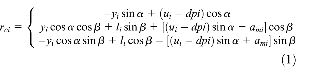
Here,
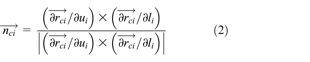
The unit normal line of the rack tooth surface can be determined by equation (2)
The tooth surface of the cutter is represented in the gear coordinate system

Here,
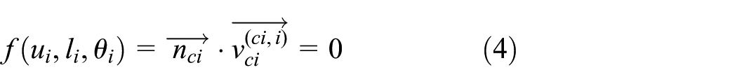
The tooth surface of the cutter envelops gear tooth surface during the machining process, which must satisfy the following meshing equations
Here,
Due to the machining and manufacturing errors, the actual tooth surface of the gear is different from that of the theoretical tooth surface, and then is a smooth curved surface after the grinding, directly sampling the three-coordinate data through Non-Uniform Rational B-Splines (NURBS) to fit the actual tooth surface, so that the precision requirement of less than 1 µm is often difficult to achieve, and when the digital tooth surface is subjected to tooth contact analysis (TCA), the iteration is too much in the calculation process, and the calculation efficiency is low. Therefore, the actual tooth surface is constructed by superposing the theoretical tooth surface with the normal error surface.
The actual tooth surface normal vector and position vector are expressed as follows


Here,
The theoretical tooth surface is generated by the rack cutter, the fitted deviation surface

Here,
The tangent vector of deviation surface along the

The helical gear has a marginal contact when meshing in and meshing out; the tangent line along the side edge of the active gear must be perpendicular to the normal line at the contact point on the tooth surface of the passive gear.
When the small gear tooth side edge is in contact,

When the top of the small gear tooth is in contact with the edge,

Here, given
Mechanism of uneven load of tooth surface
Uneven load caused by shaft bending deformation and installation errors
Generally, high power gear transmission system of warship adopts herringbone gears with big carrying capacity and better running stability. Due to the inevitable presence of manufacturing and installation errors, the left and right sides of two pairs of helical gears are not completely symmetrical, and the transmission torques at the two ends are not equal. Moreover, herringbone gear tooth width is bigger, and the shaft torsional deformation is obvious, which can cause tooth surface deviation. Therefore, the small gear generally adopts axial floating installation in marine ship power rear drive system, through the axial floating gap of the automatic fine-tuning, to achieve that the transmission torques at both ends of the shaft are equal. The bending deformation caused by shaft angle and center distance errors will increase. Schematic diagram of the shaft bending deformation is shown in Figure 2. Tooth surface carrying loads which are uniform or not have considerable contribution to deformation, as well as bending deformation. It has nonlinear characteristics, wherein both bending deformation and installation errors are changed by the tooth surface carrying loads which are uniform or not. Bending deformation is calculated by its influence function.

Schematic diagram of the shaft bending deformation.
In this section, the shaft angle error caused by bending deformation and center distance installation error are proposed. The influence function of bending deformation uses the following approximate equation


Here,
Let us assume that the shaft angle error and center distance installation error are stable random number and obey the normal distribution. The following relational expressions are given by


Here,
Here, the credibility is 0.95. The integrated installation errors that caused by bending deformation superimposed over one another can be expressed as

Here,
Uneven load caused by shaft torsional deformation
The flexibility matrix of warship power rear drive system is composed of two parts: one part is the normal flexibility matrix which generated by the unit normal load of the tooth surface, and the other part is the additional flexibility matrix which generated due to torsional deformation. In addition, the diameter and section modulus in torsion for passive wheel are big and then the torsional deformation effect is very small. Therefore, in this work, only torsional additional flexibility of the small gear is considered. In this section, using one-dimensional finite element method (FEM) to calculate the shaft torsional deformation, the gear is divided into n segments corresponding to the tooth surface mesh in the axial direction, and the n + 1 node is arranged. Schematic diagram of the shaft torsion deformation is shown in Figure 3.
Schematic diagram of the shaft torsion deformation.
Figure 3 shows that the gear is divided into six sections along the axis. Input torque from the right-hand end, the normal flexibility matrix of warship power rear drive system, is given by

Here,
Like any other design process, gear optimization design is in constant evolution to meet the demands and expectations of customers on the final product. In addition, for warship power rear drive system applications, optimization of tooth surface with minimum of flash temperature and vibration acceleration RMS have become key issues which should be addressed in gear design. Based on these considerations, the flowchart of tooth surface load uniform optimization is given in this article. The flowchart of tooth surface load uniform optimization is shown in Figure 4.

Flowchart of gear load uniform optimization.
Example verification and analysis
Overview of tooth surface flash temperature
In this section, the genetic algorithm is combined with the optimization calculation model with the objective of the minimum value of tooth surface flash temperature leading to the best accordance with regard to marine ship practical applications representing the gear performance. After modification, the two gears tooth surfaces are points contact, and the load extends from the point contact to the surface contact, neglecting the width of the instantaneous contact area of the elliptical contact, taking into account the no-load transient elliptical long axis on the tooth surface gap effect, the load variation trend along the contact line and the oil film thickness are necessarily not equal, therefore, line contact along the instantaneous contact ellipse axis is still occurring. According to the load tooth contact analysis (LTCA) model, the distribution of load density on the long axis is given by

Here,
Here,


Here,
Based on the concept described above, the following calculating formula of accumulated flash temperature of the whole tooth surface is given in this article


Here,
Optimization analysis of gear with minimum of flash temperature
Tooth surface flash temperature from the gear operating conditions and environment leads to modifications of the path of contact and transmission errors, which affect the way bevel gears mesh under load. Bonding damage on the tooth surface is regarded as a critical instantaneous local contact temperature, consisting of the flash temperature and a mean surface temperature, formed from the sum of the mean temperature and integrated flash temperature. In this section, the interest of this work is the optimization analysis of gear with minimum of flash temperature, such as herringbone gear, helical gear, and spur gear. The object study for this purpose is the herringbone gear, helical gear, and spur gear.
Optimization analysis of herringbone gear
Tooth surface flash temperature distributions of herringbone gear are shown in Figure 5; the contact lines of herringbone gear average flash temperatures are shown in Figure 6; the optimization of herringbone gear meshing line vibration accelerations is shown in Figure 7; and the herringbone gear parameters and material parameters used in the present article are listed in Table 1.

Flash temperature distribution of herringbone gear.

Herringbone gear average flash temperature.
Herringbone gear meshing vibration acceleration.
The parameters of herringbone gear pairs.

The lubrication condition of tooth surface is improved by optimization, the tooth surface flash temperature decreases significantly at mesh-in and mesh-out ends, but the tooth surface flash temperature near the node unit is difficult to drop down as shown in Figure 5. The average flash temperature of tooth surface with optimization is 48% lower than that of the former as shown in Figure 6. After optimized modification, the vibration acceleration of meshing line is reduced by 51% in Figure 7.
Optimization analysis of helical gear
The flash temperature distributions of helical gear tooth surface are shown in Figure 8.
Flash temperature of helical gear tooth surface.
The average flash temperature distributions on contact line of helical gear are shown in Figure 9, and the helical gear parameters and material parameters used in the present article are listed in Table 2.
Flash temperature on contact line of helical gear.
The parameters of helical gear pairs.

Helical and herringbone gears have been widely used in warship power rear drive system because of their advantages such as high loading capability and steady transmission performance. Based on the above analyses that are shown in Figures 8 and 9, tooth surface flash temperature decreases significantly at mesh-in and mesh-out ends, but tooth surface flash temperature near the node unit is difficult to drop down. The analysis results are consistent with that of herringbone gear.
Optimization analysis of spur gear
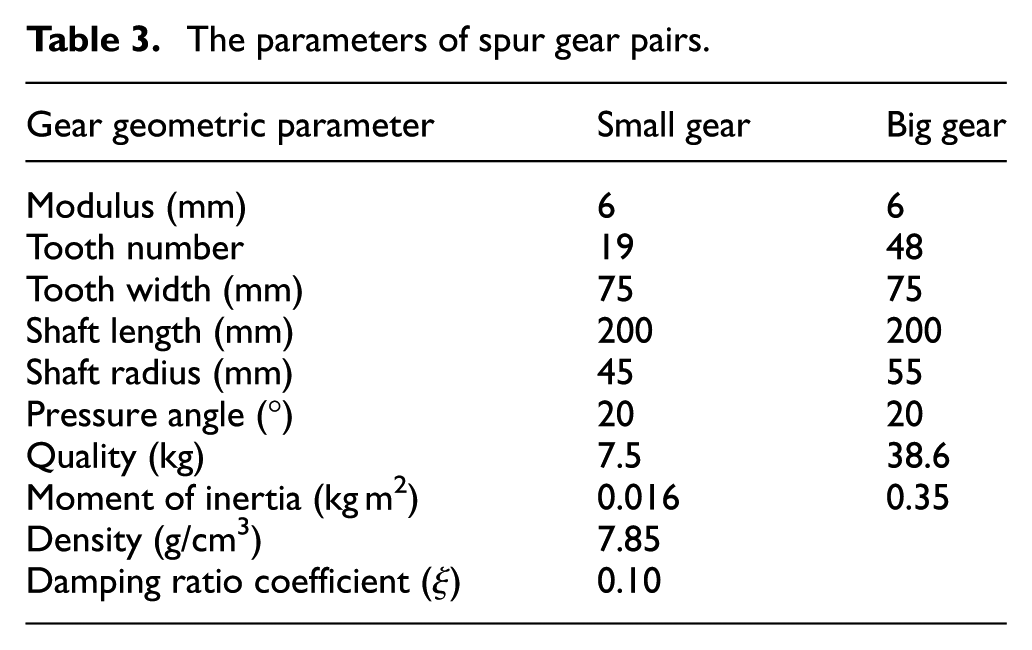
Flash temperature distributions of spur gear tooth surface are shown in Figure 10; the average flash temperature distributions on contact lines of spur gear are shown in Figure 11; and the spur gear parameters and material parameters used in the present article are listed in Table 3.
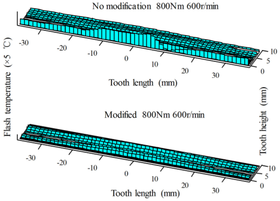
Flash temperature of spur gear tooth surface.

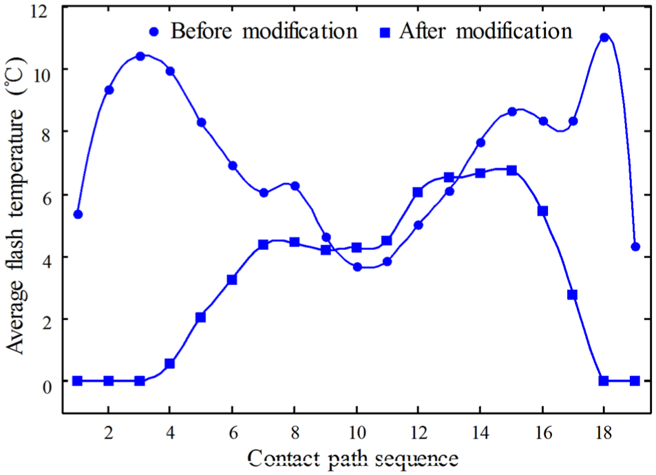
Flash temperature on contact line of spur gear.
The parameters of spur gear pairs.
From Figures 5–11 and Tables 1–3, it can be found that (1) from the point of view of the distribution of tooth surface flash temperature, tooth surface flash temperature after modification is obviously reduced compared with the modification before; and (2) from the point of view of the average flash temperature distribution on contact line, tooth surface average flash temperature after modification is obviously reduced compared with the modification before, but the tooth surface flash temperature near the node unit is difficult to drop down.
Optimization analysis of transmission gear with shaft angle error under uniform loads
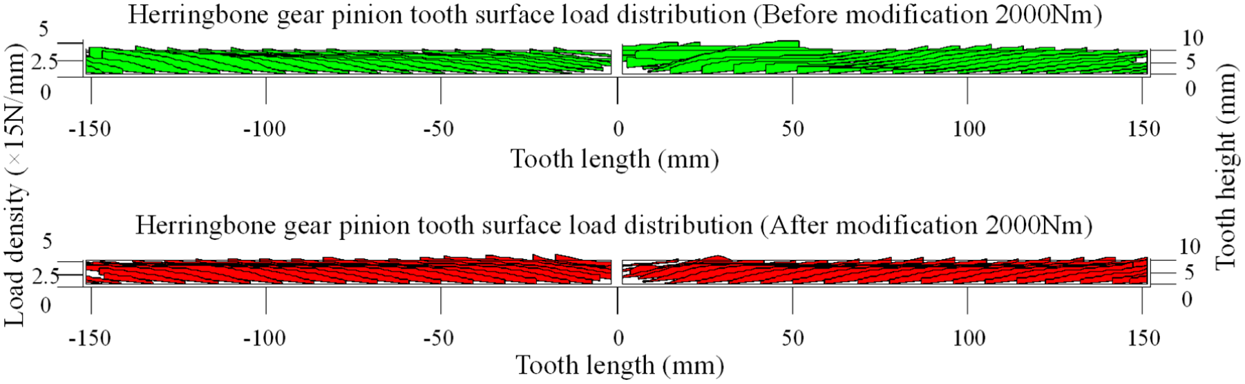
The analysis is based on the fact that shaft crossing angles and torsional deformations of a single gear or gear pair are composed of the influences of single loads occurring successively along the contact line. The contact lines are subdivided into sections of equal size, to which uniform loads are assigned. When a gear tooth is loaded, each shaft segment is subjected to a corresponding crossing angle and torsional deformation. Consequently, there will be a linear relationship between loads and shaft crossing angle. If uniform loads are applied along a contact line, each of them will cause a shaft crossing angle at each considered contact point along the contact line. In this work, the total shaft crossing angle considered contact points under the action of uniform loads is equal to the vector sum of all individual shaft crossing angles before and after parabolic modification. When considering shaft crossing angle error Y = 6″, the load distribution of herringbone gear tooth surface before and after parabolic modification (shaft crossing angle error Y = 6″) is shown in Figure 12; the herringbone gear load distribution curve is shown in Figure 13; and the herringbone gear optimized modification curve is shown in Figure 14.

Load distribution of herringbone gear tooth surface before and after parabolic modification (shaft crossing angle error Y = 6″).

Herringbone gear load distribution curve.

Herringbone gear optimized modification curve.
Actual tooth surface load distribution is again understood as the sum of various gear pairs considering torsional deformation. Tooth surface load distribution of spiral line before and after modification at contact points is regarded as crucial. When considering shaft torsional deformation, the tooth surface load distribution of spiral line before and after modification is shown in Figure 15, and the load distribution of tooth surface before and after modification is shown in Figure 16.
Tooth surface load distribution of spiral line before and after modification (torsional deformation).
Load distribution of before and after modification (when considering shaft torsional deformation).
Optimization analysis of herringbone gear. Optimization analysis of helical gear
In this section, when considering shaft crossing angle error Y = 6″, the load distribution of helical gear tooth surface before and after parabolic modification is shown in Figure 17, and the helical gear load distribution curve is shown in Figure 18.

Load distribution of helical gear before and after parabolic modification (shaft angle error Y = 6″).

Helical gear load distribution curve (2000 N m).
Optimization analysis of spur gear
In this section, when considering shaft crossing angle error Y = 18″, the load distribution of spur gear tooth surface before and after parabolic modification is shown in Figure 19; the maximum load density of contact line before and after optimization is shown in Figure 20; and the load distribution curve of spur gear tooth surface before and after optimization is shown in Figure 21.

Load distribution of spur gear tooth surface before and after parabolic modification (shaft angle error Y = 18″).

Maximum load density of contact line before and after optimization.

Load distribution curve of spur gear tooth surface before and after optimization.
From Figures 12–21 and Tables 1–3, it can be observed that (1) in terms of herringbone and helical gears, when considering shaft crossing angle, herringbone gear has obvious partial load at mesh-in end; after parabolic modification, the edge contact is avoided and the load density is increased; when considering shaft torsional deformation, the load is biased toward the input end; after spiral modification, the load distribution of tooth surface is uniform, the load density is reduced, and the modification amount is relatively small; and (2) in terms of spur gear, spur gear is easy to generate partial load at mesh-in end; after tooth profile modification, the tooth surface load is more uniform and no change in the load distribution curve, but the load density is reduced. Here, it is worth mentioning that spur tooth profile modification cannot change the load distribution, only the load density is changed.
Multi-objective optimization analysis considering installation error of load uniformity (γ = 12″)
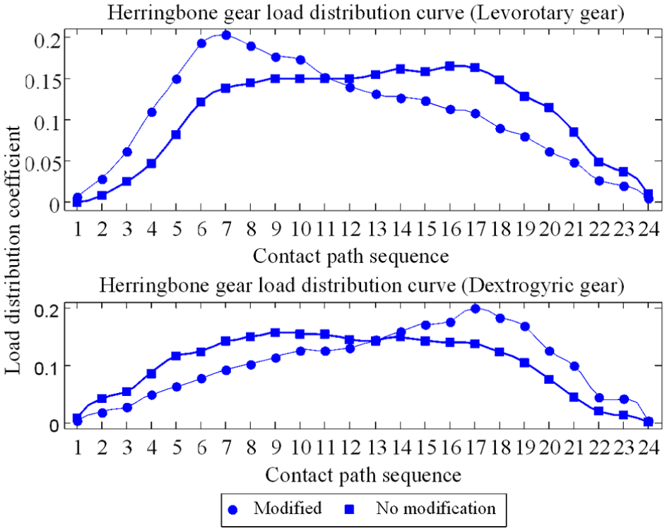
In this section, concerning the optimization minimizing tooth surface flash temperature and vibration acceleration RMS, herringbone gear tooth surfaces of characteristic optimum modification areas in Figures 22–25 have been found, which are considered as installation error of tooth surface load uniformity (γ = 12″). This reduction is mainly due to the multi-objective parameters optimization of profile modification for flash temperature and vibration acceleration RMS, but among them, only those with a greater extent minimize. Here, the herringbone gear tooth surface flash temperature distribution before and after optimization is shown in Figure 22; the herringbone gear small tooth surface load distribution before and after optimization is shown in Figure 23; the herringbone gear meshing line acceleration curve before and after optimization is shown in Figure 24; and the herringbone gear multi-load installation error amplitude variation curve before and after optimization is shown in Figure 25.

Herringbone gear tooth surface flash temperature distribution before and after optimization.

Herringbone gear small tooth surface load distribution before and after optimization.
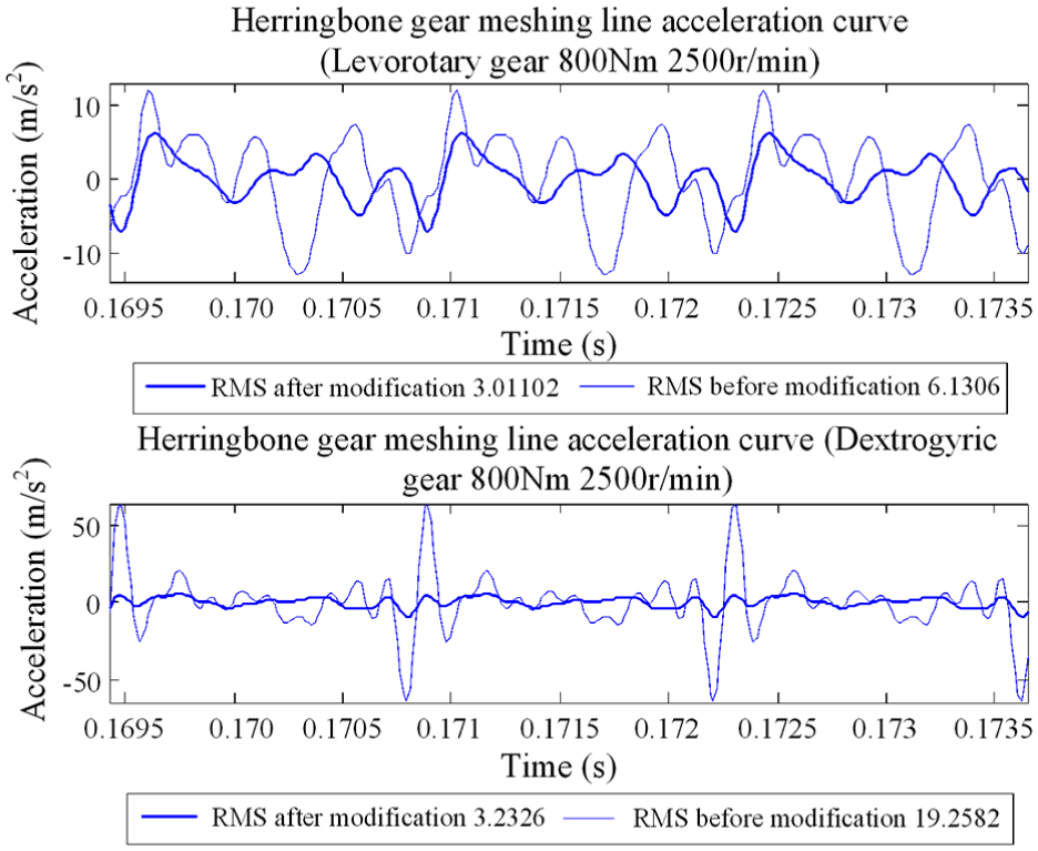
Herringbone gear meshing line acceleration curve before and after optimization.

Herringbone gear multi-load installation error amplitude variation curve before and after optimization.
From Figures 22–25, it can be obtained that (1) when considering load installation error of herringbone gear, in action of tooth surface uneven load, the small of herringbone gear has an axial movement—at this time, the channeling momentum of meshing cycle is 3.4 µm; (2) tooth surface flash temperature after modification is obviously reduced compared with the modification before; and (3) the results show that the installation error and vibration acceleration RMS after modification have decreased 68% and 76%, respectively, on average comparing with that without modification, which indicate that the multi-objective optimization proposed can lead to a significant reduction of noise and vibration in warship power rear drive system.
The previous researchers design method of the traditional field is to determine the appropriate size of the optimization on the basis of the selected transmission scheme, select the reasonable design variables, establish the correct mathematical model and then change and deal with it, for the standard mathematical programming problem, the final application of the optimal method to solve. In this article, the multi-objective optimization problem is transformed into one or a series of simple, objective solutions. The optimization of the minimum of flash temperature and vibration acceleration RMS of marine gears should be considered in the optimization design of the high load gears of warship power rear transmission system, which is important to improve gears’ meshing performance.
Conclusion
In the gear pair optimization design of a warship power rear drive system, in addition to considering the fatigue strength of tooth contact and bending, it is necessary to propose the gear elastic hydrodynamic lubrication effect and the optimization problem of the multi-objective modification, such as the minimum tooth surface flash temperature and the vibration acceleration RMS. This consideration is of great significance to improve the gear pair meshing performance of a warship power rear drive system.
This study provided the following contributions:
The lubrication condition of the tooth surface is improved by optimization, and the tooth surface flash temperature decreases significantly at the mesh-in and mesh-out ends.
From the point of view of the distribution of the tooth surface flash temperature, the tooth surface flash temperature after modification is obviously reduced compared with the case before the modification.
From the point of view of the average flash temperature distribution on the contact line, the tooth surface average flash temperature after modification is obviously reduced compared with the case before the modification, but the tooth surface flash temperature near the node unit is difficult to reduce.
When considering the shaft crossing angle, the herringbone gear has an obvious partial load at the mesh-in end; after parabolic modification, the edge contact is avoided, and the load density is increased.
When considering the shaft torsional deformation, the load is biased toward the input end; after spiral modification, the load distribution of herringbone gear tooth surface is uniform, the load density is reduced, and the modification amount is relatively small.
When considering the load installation error of the herringbone gear, in action of the uneven load of the tooth surface, the small herringbone gear has an axial movement.
The results show that the installation error and the vibration acceleration RMS after modification are reduced evidently on average compared with those without modification.
Footnotes
Acknowledgements
The authors gratefully acknowledge support from the Harbin Institute of Technology (HIT) as well as the Harbin University of Science and Technology (HUST).
Handling Editor: Yangmin Li
Declaration of conflicting interests
The author(s) declared no potential conflicts of interest with respect to the research, authorship, and/or publication of this article.
Funding
The author(s) received no financial support for the research, authorship, and/or publication of this article.