
Abstract
In order to reduce the transmission noise of drive axle hypoid gear, a method of tooth surface mismatch modification was proposed. Firstly, on the basis of establishing the grinding mathematical model of hypoid gear with cutter tilt, the theoretical tooth surface equation was derived, and the numerical tooth surface was calculated by dividing the grid points on tooth surface. Secondly, the pinion tooth surface which was full conjugated with gear tooth surface was constructed, and the tooth surface mismatch topography was established and decomposed into the first order and second order mismatch coefficients. According to the modification requirements, the pinion target surface was constructed by modifying the tooth surface mismatch coefficients, and the pinion modified machine setting parameters were acquired by establishing the pinion processing parameters corrected mathematical model. Finally, the loaded tooth contact analysis with finite element simulation and drive axle NVH (Noise, Vibration, Harshness) simulation were carried out for a pair of hypoid gear, therefore the loaded tooth contact areas, transmission errors curves, and noise simulation curves were obtained, and the simulation results show that after modification the tooth contact stress, loaded transmission errors amplitude, and NVH simulation curves value are all reduced. The road test results indicate that the drive axle hypoid gear howling phenomenon under the high speed operation can be eliminated, so the effectiveness of tooth surface modification method and NVH simulation method were verified.
Keywords
Introduction
With the rapid development of automobile industry, people have higher and higher requirements for NVH (Noise, Vibration, Harshness) performance of automobiles. As the key components in the transmission system of automobile drive axle, the meshing performance of hypoid gear directly affect the NVH performance of drive axle, so it is particularly important to ensure good meshing performance of tooth surface during the gear design and machining process. Generally, in the development process of hypoid gear of drive axle, it is difficult to ensure the meshing performance of tooth surface to meet the noise requirements of drive axle only through one design, and it is necessary to continuously improve the meshing quality through tooth surface modification, so as to meet the requirements of vibration reduction and noise reduction of drive axle. Many scholars have carried out relevant researches on tooth surface modification and vibration and noise reduction technology of hypoid gear.
In the aspects of tooth surface modification of hypoid gear, Fan 1 introduced the concept of ease off topography to describe the mismatch relationship during the meshing process of spiral bevel gear. Artoni et al. 2 studied the modification method of hypoid gear to reduce transmission errors and low tooth contact stress by presetting the optimal loaded contact area shape and position. Shih and Fong 3 proposed a novel ease off tooth surface topology modification method to pre-control meshing performance for face hobbing lapping process. Jiang et al. 4 studied the design method of pinion topography modified surface by presetting the characteristic parameters of tooth contact area and transmission error curves, and the best modified surface was obtained by combining the loaded contact analysis method. Wang et al. 5 developed the optimization algorithm to modify the pinion tooth surface by taking the direction of contact trace and the amplitude of transmission error as optimization variables and taking the minimum amplitude of loaded transmission error as the goal. Du et al. 6 acquired the pinion target surface which can meet meshing performance by modifying the pinion based surface along the meshing line and contact line. Yang et al. 7 put forward the constructing method of gear target surface by modifying tooth surface curvature. Mu et al. 8 proposed a method of tooth surface topography modification for high contact ratio spiral bevel gear, which can reduce the loaded transmission errors by using the high-order transmission error instead of parabolic transmission error. Nie et al. 9 proposed the method of tooth surface deviations equivalent correction only modifying the pinion tooth surface by calculating the mismatch values between the pinion actual surface and pinion designed surface. Cao et al. 10 constructed the ease off flank topography for aviation spiral bevel gear with high-order transmission errors by modifying the conjugate flank, which can accurately control the high-order transmission errors and tooth contact patterns by controlling the whole tooth surface structure. At present, the GEMS software of Gleason company and KIMOS software of Klingelnberg company also give the ease off topography modification method. From the software interface, it can be seen that this method adjusts tooth surface mismatch topography relationship by controlling five parameter values, such as spiral angle difference value, pressure angle difference value, tooth lengthwise crowning value, tooth profile crowning value, and tooth longitudinal twist value, however, these two companies have not disclosed the principle and algorithm of ease off topography modification method.
In the aspects of vibration and noise reduction of hypoid gear, Jiang and Fang 11 presented an active modification design method of hypoid gear with zero loaded transmissions error amplitude, on the basis of establishing the bending-torsional-axial coupling dynamic lumped mass model for hypoid gear, and the best modified tooth surface was determined by an optimizing minimal mean square value of normal vibration. 12 In order to reduce the noise caused by high-order harmonics of loaded transmission errors, Su et al. 13 proposed the design method of contact path with large contact ratio along the tooth length direction, on this basis, the design method of hybrid transmission errors of spiral bevel gears was introduced to reduce the noise, and determined the local synthetic parameters with minimum fluctuation of loaded transmission errors and symmetry of geometric transmission errors under working load through optimization to obtain the pinion modified tooth surface. 14 Nie et al. 15 studied the relationship between the loaded transmission errors and the noise curve of drive axle to optimize the NVH performance of drive axle by controlling the amplitude of loaded transmission errors. In order to control vibration and noise of drive axle, Liu et al. 16 established the finite element model of drive axle assembly to calculate the transmission errors of drive axle hypoid gear by the ABAQUS software, which analyzed the influence of different torques on the loaded transmission errors.
The above researches show that the tooth contact area and transmission error are two important guidelines to judge the tooth contact performance, which have a direct impact on the NVH performance of drive axle. By comprehensively correcting these two indexes through tooth surface modification, the better vibration and noise reduction effects can be achieved. On the basis of the above researches, this paper puts forward a novel tooth surface modification method of hypoid gear based on tooth surface mismatch correction, and this method can correct tooth contact area and transmission error by pre-controlling the mismatch topography relationship of tooth surface. Different from the ease off modification method in GEMS software and KIMOS software, the proposed method in this paper can decompose the tooth surface mismatch topography along five directions by means of the second-order difference surface, thereby obtaining the tooth surface mismatch coefficients, and modifying the tooth surface mismatch relationship by changing the tooth surface mismatch coefficients. In order to check the tooth meshing performance after modification, the method of tooth contact analysis and loaded contact simulation with finite element technology are applied, and the vibration and noise reduction effect after tooth surface modification can be verified by the NVH simulation and road test experiment of drive axle.
Tooth mismatch modification and meshing performance analysis flow chart
In order to clearly understand the tooth surface mismatch modification method and meshing performance evaluation method proposed in this paper, the flow chart of technical route is shown in Figure 1. From Figure 1, it can be seen that the pinion tooth surface modification can be realized by correcting tooth surface mismatch topography, whether the meshing performance of modified tooth surface meets the expectation or not need to be evaluated by loaded contact simulation technology, whether the modified tooth surface meets the requirements of vibration and noise reduction still need to be verified by NVH simulation and road test experiment. If the meshing performance of modified tooth surface can not meet the requirements of vibration and noise reduction, it is necessary to go back and correct the tooth surface mismatch topography again. Next, this paper will discuss the key technologies such as tooth surface mismatch modification method, loaded tooth contact analysis with finite element and drive axle NVH simulation.

Flow chart of tooth mismatch modification and meshing performance analysis.
Tooth surface numerical calculation
Theoretical equation of tooth surface
In the manufacturing process of hypoid gear of automobile drive axle, the gear grinding technology with HFT method is widely used because of high machining efficiency. For the HFT method, on the pair of hypoid gear, the gear can be ground by formate method, and the pinion can be ground by generating method with cutter tilt. In the process of gear grinding by HFT method, the cutter head rotates around its axis to form a imaginary crown gear, and the tooth surface of workpiece can be generated by the imaginary crown gear with cradle rotation. According to the relative movement and position relationship between cutter head and workpiece, the mathematical model of gear grinding with cutter tilt is established, 17 as shown in Figure 2.
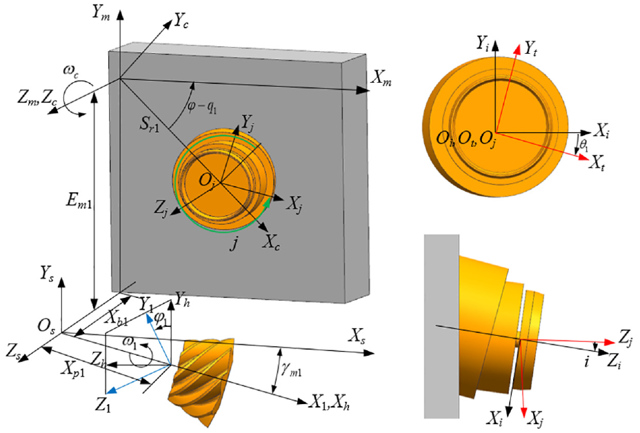
Machining mathematical model of gear grinding with cutter tilt.
In Figure 2,
According to the structure of cutter head, the cutter head equation and unit normal vector in the cutter head system


Here,
The tooth surface equation of workpiece is obtained by a series of coordinate transformations from the tool surface equation. According to the relationship between the coordinate systems, the tooth surface equation and unit normal vector of workpiece can be obtained by space transformation.


Here,
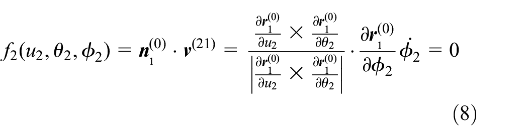
In the generating process between the imaginary crown gear and the workpiece, the meshing equation can be expressed by the following equation (5).

Here,
In Figure 2, the machining mathematical model of gear grinding with cutter tilt is a uniform model, which is mainly used for pinion grinding, but it is also applied to gear grinding with formate method. Here, only need to substitute the gear formate machining parameters into the equations (3) and (4), the tooth surface equation and unit normal vector of gear can be obtained, represented as
Discrete calculation of tooth surface
The tooth surface of hypoid gear is a complex spatial surface, in order to obtain the accurate tooth surface model, it is necessary to obtain the grid points coordinates on the tooth surface. Therefore, by discretizing the tooth surface of hypoid gear, the grid points are divided on the axial section of gear, as shown in Figure 3. The two-dimensional coordinates of each grid point are calculated by using the gear geometric parameters, and then the equation is established by the corresponding relationship between the spatial tooth surface and the grid points of the axial section, so that the three-dimensional coordinate data of tooth surface can be calculated.
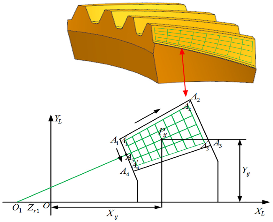
Tooth surface grid division.
In Figure 3,

Construction and decomposition of tooth surface mismatch topography
Pinion conjugated tooth surface
Figure 4 shows the meshing mathematical model of hypoid gear assembly,

Meshing mathematical model of hypoid gear assembly.
Transforming the gear tooth surface equation

Here,
When the pinion tooth surface is completely conjugated with the gear tooth surface, the relationship
Here,
Tooth surface mismatch topography
In order to facilitate the definition of tooth surface mismatch topography, here, the pinion tooth surface derived by equation (3) is defined as the pinion theoretical tooth surface which is represented as
Figure 5 shows the relationship between the pinion theoretical tooth surface and pinion conjugated tooth surface. Point
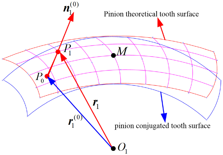
Relationship between the pinion theoretical tooth surface and pinion conjugated tooth surface.
According to the vector relation in Figure 5, the formula

Substituting the coordinates of all grid points on the tooth surface into the equation (9), respectively, and solving the equation (9) can obtain the tooth surface deviations
Tooth surface mismatch coefficients decomposition
Because the tooth surface mismatch values are composed of the tooth surface deviations of all grid points between the pinion theoretical tooth surface and pinion conjugated tooth surface, and its essence is also a kind of tooth surface deviations. Generally speaking, the tooth surface deviations can be approximately expressed by the second-order surface (as shown in Figure 6)

Here,

Tooth surface deviations with second-order surface.
If the tooth surface deviations of all grid points on the tooth surface are known, then the equation (10) is expanded to be expressed as the following matrix form. 18

According to Figure 3, the two-dimensional coordinates
Tooth surface mismatch modification and pinion machine setting parameters correction
Tooth surface mismatch modification
Tooth surface mismatch topography reflects the meshing situation between the pinion tooth surface and the gear tooth surface, so in order to change the meshing performance of the current tooth surface, it can be achieved by modifying the mismatch relationship between the tooth surfaces, and modifying the tooth surface mismatch topography can be achieved by changing the five tooth surface mismatch coefficients

Relationship between the pinion current flank and pinion target flank.
Pinion machine setting parameters correction
The pinion current flank can be expressed by a vector equation

After differentiating equation (12), the multiplication the unit vector
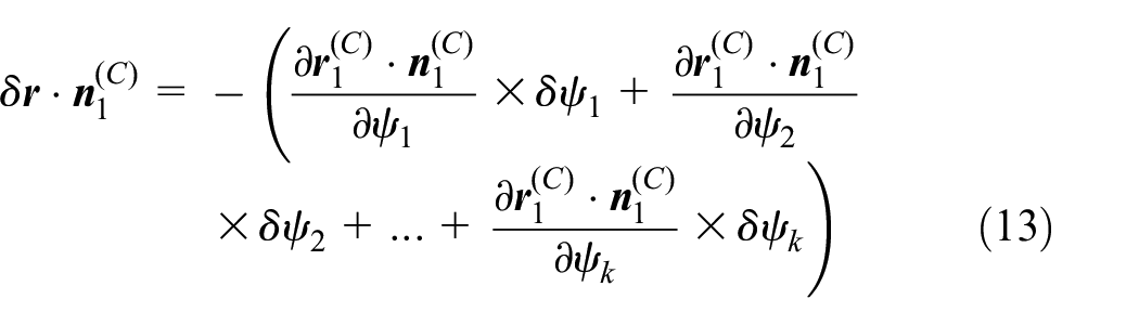
Here,
If the deviations of all grid points on the tooth surface are known, the tooth surface deviation equation can be expressed as a matrix equation as follows

Here,

Here,

Example analysis
In order to verify the method of tooth surface mismatch modification proposed in this paper, taking a pair of hypoid gear of drive axle as the example, the tooth surface modification process for gear concave is carried out and analyzed. Table 1 gives the geometric parameters of hypoid gear, and Table 2 gives the grinding machining parameters.
Geometric parameters of hypoid gear.

Machining parameters of hypoid gear.

Figure 8 shows the tooth contact analysis results for the original gear concave. From Figure 8 it can be seen that the tooth contact area for gear concave is in diagonal contact, and the amplitude of transmission error is approximately 30 μrad.

Tooth contact analysis results for the original gear concave: (a) tooth contact area and (b) transmission error.
The existing literature researches show that reducing the tooth contact stress and the amplitude of loaded transmission error can reduce vibration and noise. Therefore, the topography modification scheme for gear concave is determined by reducing the diagonal trend of tooth contact area, increasing the tooth contact area and reducing the designed amplitude of transmission error. According to this modification scheme, on the basis of the influence laws of tooth surface mismatch coefficients on tooth surface contact area and transmission error, the five tooth surface mismatch coefficients are corrected. Table 3 gives the tooth surface mismatch coefficients before and after modification. Figure 9(a) shows the original tooth surface mismatch topography, and Figure 9(b) shows the tooth surface mismatch topography after modification. The deviations between the pinion original tooth surface and pinion target tooth surface are shown in Figure 10.
Tooth mismatch coefficients before and after modification.


Mismatch topography for the: (a) original tooth surface and (b) modified tooth surface.

Deviations between the pinion original tooth surface and pinion target tooth surface.
Here, selecting the grinding wheel radius, tilt angle, swivel angle, radial distance, center roll position, machine root angle, work offset, machine center to back, sliding base, ratio of roll as the corrected parameters, by correcting these pinion machining setting parameters, the pinion original tooth surface can approach the pinion target tooth surface continuously. Table 4 gives the machining setting parameters for pinion convex after modification, and Figure 11 shows the deviations between the pinion tooth surface after modification and pinion target tooth surface. From Figure 11, it can be seen that the maximum tooth surface deviation is 4.3 μm < 10 μm (0.01 mm), which indicates that the pinion tooth surface after modification is equivalent to the pinion target tooth surface.
Machining setting parameters for the pinion convex after modification.

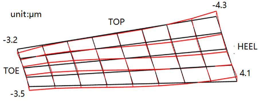
Deviations between the pinion tooth surface after modification and pinion target tooth surface.
The tooth contact analysis for the tooth surface after modification is carried out, and the simulation results are shown in Figure 12. Compared with Figures 8 and 12, it can be seen that after modification, the diagonal trend in the contact trace of the gear concave decreases, the major axis of instantaneous contact ellipse increases, the contact area increases, and the transmission error amplitude decreases (from 30 to 14.8 μrad), which meet our expected modification requirements.

Tooth contact analysis results for the gear concave after modification: (a) tooth contact area and (b) transmission error.
Loaded tooth contact analysis with finite element method
The meshing performance of hypoid gear under the actual working conditions affects the vibration and noise of automobile driving axle. The loaded tooth contact area and the loaded transmission error are two main indexes to evaluate the meshing performance under the actual working conditions. In this section, the loaded tooth contact analysis with finite element method for the hypoid gear pair before and after modification is carried out based on the ABAQUS software to verify the modification effect. In order to facilitate the finite element simulation analysis, the three-dimensional model of hypoid gear is divided, and the five tooth finite element analysis model is established, and the hexahedral grid is used for grid division, as shown in Figure 13, and the pre-processing parameter settings for the finite element analysis are given in Table 5.

Finite element analysis model: (a) three-dimensional model of hypoid gear and (b) five tooth finite element analysis model.
Parameter settings for the finite element analysis

After the finite element analysis based on the ABAQUS software is finished, the maximum contact stress of each unit on the contact surface at different times in the whole analysis process can be obtained by running the python script file. The shape of the contact stress nephogram displayed at each time is equivalent to the instantaneous loaded tooth contact ellipse, and the whole loaded tooth contact area can be obtained by extracting the maximum contact stress at different times.
Considering that the deceleration surface (gear concave) of the automobile drive axle works in the high-speed sliding stage, the load on the tooth surface is below 100

Loaded contact area for the original tooth surface.
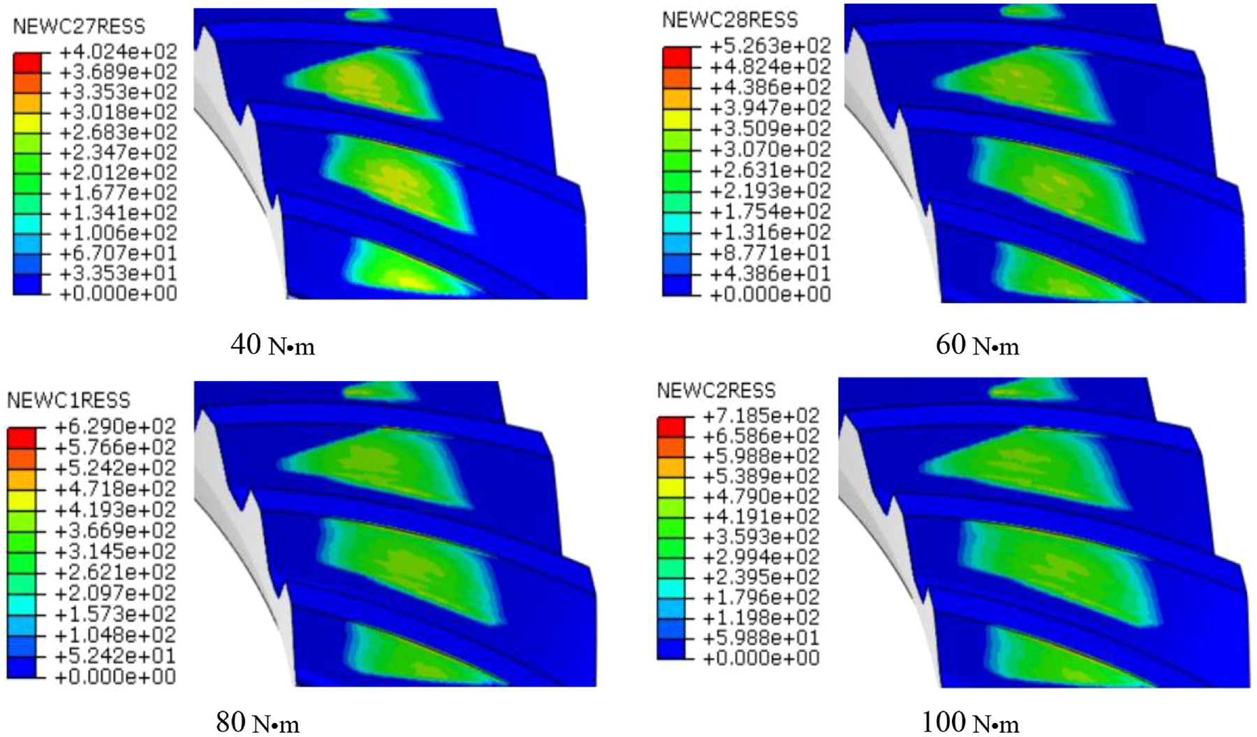
Loaded contact area for the modified tooth surface.
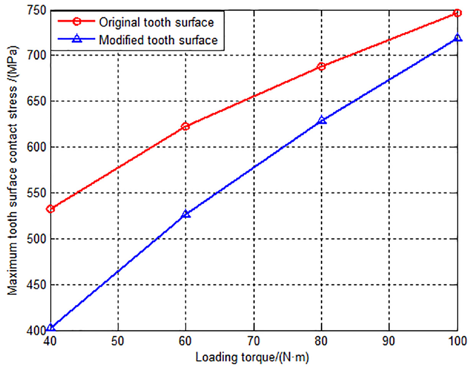
Variation of maximum tooth surface contact stress with load torque before and after tooth surface modification.
Comparing Figures 14 and 15, it can be seen that the tooth contact area increases gradually with the increase of load, and under the same load, the diagonal trend in the contact area of the modified tooth surface is smaller than that in the original tooth contact area, and the area of the modified tooth contact area is larger than that of the original tooth contact area. From Figure 16, it can be seen that the maximum contact stress of the modified tooth surface is less than that of the original tooth surface under the same load torque.
Figure 17 shows the loaded transmission error curves before and after tooth surface modification under the four loads, and Figure 18 shows the variation of loaded transmission error amplitude with load torque before and after tooth surface modification.

Comparison of loaded transmission error before and after tooth surface modification.
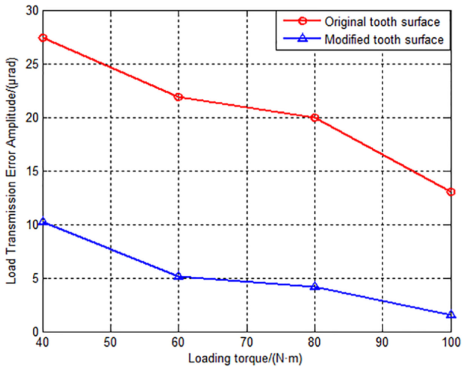
Variation of loaded transmission error amplitude with load torque before and after tooth surface modification.
From Figures 17 and 18, it can be seen that the fluctuation amplitude of the loaded transmission error curves decrease gradually with the increase of load torque, and under the same load torque, the fluctuation amplitude of loaded transmission error of the modified tooth surface is obviously smaller than that of the original tooth surface. These simulation results show that the loaded tooth meshing performance is improved after tooth surface modification, which is beneficial to the vibration and noise reduction of drive axle.
Drive axle NVH simulation and road test experiment
NVH simulation of drive axle
In order to verify the effect of noise reduction after tooth surface modification, the NVH simulation analysis is carried out for a light passenger drive axle based on the MASTA software. Firstly, the components of the drive axle are modeled by the UG software, then the established models are imported into the MASTA software, and the NVH simulation analysis model of drive axle is established, as shown in Figure 19. Measuring points are set on the input end of the main reducer of drive axle, and the noise curve is obtained by the NVH simulation.

Drive axle simulation model with MASTA software.
The noise curves in three directions, namely X, Y, and Z, can be obtained through measuring the vibration signal on the test point. Because the Z direction is vertical to the road surface and the vibration and noise in this direction is the largest, the noise curve in the Z direction is taken as the evaluation basis. Figure 20 shows the noise curves before and after tooth surface modification under the four working conditions.

Comparison of NVH noise curves before and after tooth surface modification.
From Figure 20, it can be seen that the NVH noise curves of drive axle after tooth surface modification are lower than that before tooth surface modification under the four loads of 40, 60, 80, and 100
Comparing Figures 18 and 20, it can be seen that after modification the noise curve of drive axle reduces gradually with the decreases of loaded transmission error amplitude under the same load, this shows that the loaded transmission errors of hypoid gear have directly influence on the noise of drive axle.
Road test experiment of drive axle
In order to further verify the validity of tooth surface modification and NVH simulation results of drive axle, the gear grinding experiment and NVH road test experiment are carried out for the modified tooth surface. Figure 21 shows the process of pinion grinding and measuring, and Figure 22 shows the tooth contact patterns for gear concave before and after tooth surface modification. By comparing Figures 8, 12, and 22, it can be seen that the shape, position, and size of actual rolling contact area are basically consistent with the tooth contact area by tooth contact analysis.

(a) Pinion grinding and (b) tooth surface measurement.

Rolling tooth contact patterns before and after tooth surface modification: (a) original tooth contact pattern for gear concave and (b) modified tooth contact pattern for gear concave.
The hypoid gear is loaded into the drive axle and the road test experiment is carried out. The road test is carried out on a smooth and dry highway, and the equipment is mainly the LMS collector, vibration sensor, and microphone. The arrangement of measuring points is to paste the vibration sensor on the shell above the outer end of pinion bearing of the main reducer of driving rear axle, as shown in Figure 23. Fixing the microphone on the driver’s back seat to test the interior noise value. The road test is carried out under the condition of 5-speed reduction, and the speed ratio of the gearbox is 0.76, corresponding to the gear order n = 8/0.76 = 10.53.

Sensor measuring point of road test experiment: (a) vibration sensor measuring point and (b) microphone measuring point.
Figure 24 shows the colormap diagram obtained by LMS road test before and after tooth surface modification. In Figure 24(a), the red area corresponding to the gear order (n = 10.53) curve indicates that this pair of hypoid gear has generated high-speed howling. In Figure 24(b), the disappearance of the red area corresponding to the gear order (n = 10.53) curve indicates that the high-speed howling after tooth surface modification has been eliminated. By comparing Figure 24(a) and (b), it can indicate that the NVH performance of drive axle is improved after tooth surface modification, which further verifies the effectiveness of tooth surface modification method and the feasibility of NVH simulation method.

Comparison of colormap diagram before and after tooth surface modification: (a) colormap diagram for the original tooth surface and (b) colormap diagram for the modified tooth surface.
Conclusions
In this paper, aiming at the noise reduction of automobile drive axle, a method of tooth surface mismatch modification of hypoid gear was proposed. On the basis of establishing the mathematical model of pinion grinding with cutter tilt, the construction method of tooth surface mismatch topography was studied, and the tooth surface mismatch topography was decomposed and modified by use of the second-order surface. By establishing the mathematical model of pinion machining parameters correction, the pinion corrected machining parameters were obtained. On this basis, the loaded tooth contact analysis before and after tooth surface modification was carried out by the finite element method, and the NVH performance of drive axle before and after tooth surface modification was analyzed based on the MASTA software. Finally, the gear grinding experiment and road test experiment were completed. Through this study, we can draw the following conclusions:
(1) The tooth surface mismatch modification method proposed in this paper can realize the free modification of tooth surface. According to the influence laws of tooth surface mismatch coefficients on tooth surface topography, the tooth surface mismatch coefficients are modified to obtain the required tooth surface contact area and transmission error, and this modification method is intuitive and convenient.
(2) Through the loaded tooth contact analysis with finite element method and NVH simulation of drive axle, it is known that the change trend of NVH noise curve of drive axle after tooth surface modification is consistent with the change trend of loaded transmission error amplitude, which indicates that the transmission noise of drive axle can be reduced by reducing the loaded transmission error amplitude under the actual working conditions.
(3) The road test experiment of drive axle shows that after tooth surface modification, the howling of drive axle is eliminated during the high-speed deceleration sliding, which shows that the noise reduction effect of drive axle can be achieved through the tooth surface modification. It further verifies the effectiveness and feasibility of the method of tooth surface modification and the NVH simulation method of drive axle proposed in this paper.
Footnotes
Acknowledgements
We are grateful to the reviewers and editors for their valuable comments and suggestions.
Handling Editor: Chenhui Liang
Declaration of conflicting interests
The author(s) declared no potential conflicts of interest with respect to the research, authorship, and/or publication of this article.
Funding
The author(s) disclosed receipt of the following financial support for the research, authorship, and/or publication of this article: The authors are grateful to the National Natural Science Foundation Council of China; this project was performed under the Grant No. 51705134.