
Abstract
In order to solve these problems, such as excessive fluid velocity, large differences in output for all turbine level and disorder of flow field, variable geometric method was put forward as an improved method for turbine blade. The output performance of last blade and last three blades is studied by changing the stagger angle of blade for 10-stage turbine. The results show that the aerodynamic efficiency was increased by 3.72% for the variable geometry technology used in the last-stage blade. The variable geometry technology was used in last three stages blades of a 10-stage turbine, the aerodynamic efficiency increased by 4.88%, the output performance is more average than before, the fluid velocity in the flow field is reduced, and the phenomenon of dewatering is controlled.
Keywords
Introduction
Variable geometry turbine technology is an effective way that can improve the adaptability of the turbodrill under complex operating conditions, which can make the turbodrill acquire good performance. 1 Variable geometry technology was first used in the field of the aircraft engines. As early as 1950s, NASA was the first to study the feasibility of a variable geometry turbine.2,3 Experimental studies obtained by ML Kaesser 4 and NASA Lewis center shown that changing the static blade angle can effectively control turbine flow. In other words, the throat area will change the flow capacity of the turbine by rotating stator blade. The idea of variable geometry has also been widely applied to ships, 5 automobiles, 6 and so on. Chmielewski and Gieras 7 studied the effect of variable geometry combustor on the performance and emissions from miniature gas turbine engine. It was proved that the performance of the variable geometry combustor is better than that of the standard and fixed geometry combustor. F Haglind 8 studied the influence of variable geometry on the part-load performance of a gas turbine. The results show that variable geometry can improve the part-load performance of the gas turbine. F Haglind 9 analyzed the effects of variable geometry gas turbines on the part-load effects of combined circulation used for ship propulsion. The results suggest that variable geometry gas turbine can improve the partial load performance of combined cycle. Hou et al. 10 utilized variable geometry technology to study coupling flow field between dynamic/static cascade of power turbine and asymmetric exhaust duct for the end of a MW-grade gas turbine. When the angle of the guide vanes increases, the performance of the dynamic and static cascades and the exhaust duct for the power turbine decreases obviously. Sun et al. 11 studied the flow patterns of the general parameters and end wall of the cascade using variable geometry technology. When the rotatable guide vane rotates from a negative angle to a positive angle, the leakage decreased gradually, and the total pressure recovery coefficient increases gradually. Xu et al. 12 modified spherical end wall of the high-pressure stage for the turbine by variable geometry, and carried out numerical simulation for the high- and low-pressure flow of the turbine. The result shows that the adjustable high-pressure guide vane can lead to the change of the inlet angle of the low-pressure turbine, which affected the flow pattern and press loss of the low-pressure guide vane. Although, rotating guide vane can realize the variable geometry of the turbine, it also causes the tip clearance, so how to reduce the tip clearance becomes the key problem in the design. Moreover, the design of the end wall for the spherical surface can not only ensure the rotation of the stationary blade but also minimize the tip clearance, which is a good choice for variable geometry. 13 Hu 14 first proposed the spherical design idea of blade tip. Then, Yue et al., 13 Yin, 15 and Song 16 preliminarily explored the application of the modeling technology of the cylindrical and spherical end wall in variable geometry turbine. Thus, the variable geometry technology is mainly used in the fields of gas turbine and turbo, but there is very little applied research in the field of turbine drilling. Therefore, the pneumatic turbodrill blade is taken as subject in the study and the three-dimensional (3D) finite element simulation model was established in the article. In this article, the variable geometry technology is applied to change the geometric installation angle of turbine blades, and the influence of variable geometry technology on the output performance of single-stage and multistage turbine is discussed, respectively, so as to get different output performances, improve the problems of traditional turbodrill in gas medium, and improve the overall output efficiency of multistage turbine. It is proved that the output performance of the single-stage and multistage turbine can improve by variable geometry technique. In this article, by changing the blade installation angle, the last-stage blade and the last three stages’ blade for 10-stage turbine were, respectively, studied by variable geometry. The result indicates that aerodynamic efficiency of the last-stage turbine blade and the last three stages’ blades has been improved significantly and the output performance of all levels blades becomes more average than before. The research conclusions can provide a theoretical support and reference significance for the design of turbine blade.
Characteristics analysis of the turbine drill
The section of structure parameters and flow parameters for the rotor blade is shown in Figure 1 (the section of stator blade is similar to that of the rotor, but the bending direction is opposite, where dotted lines are the position of the blade rotation).

Blade structure parameters and flow parameters.
Where
It is assumed that the structural angle of the blade is equal to the liquid flow angle under the condition of no shock (
For the turbine of certain structural dimensions, the following equations can be obtained


where
According to speed polygon of turbine (Figure 2), the stagger angle

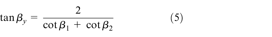
Equations (4) and (5) show that the stagger angles of the stator blade and rotor blade have an important effect on the flow angle of the inlet and outlet of the stator and rotor.

Speed polygon of turbine.
Under the action of hydraulic force for single-stage turbine, the torque

where
Power

According to Figure 3,


Velocity polygon of inlet and outlet of rotor: (a) relationship of rotor inlet velocity and (b) relationship of rotor outlet velocity.
By substituting equations (3), (8), and (9) into equations (6) and (7), the following equation can be obtained


Considering


Equations (12) and (13) show that the inlet and outlet flow angle of the stator and rotor have an important effect on the power and torque of a single-stage turbine. And, flow angle is affected by the stagger angle. Therefore, it is necessary to study the influence of stagger angle of stator and rotor blade on the output performance of turbine.
The input power of the turbine,

where
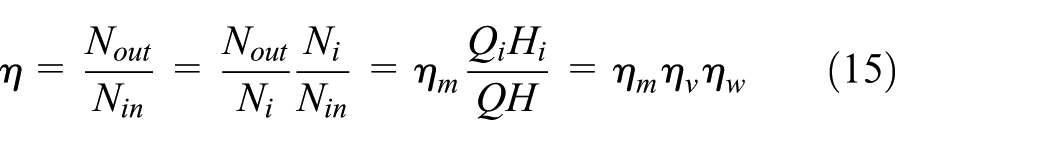
where

According to equation (16), pneumatic power

Study on blade by variable geometry technology
Computational model and numerical method
The 3D model of the blade is shown in Figure 4. The TurboGrid module was used to mesh because it quickly draws out high-quality structured grids. According to the relatively smooth feature of the turbine blade profile and the periodicity of the flow path, hexahedral mesh was used.
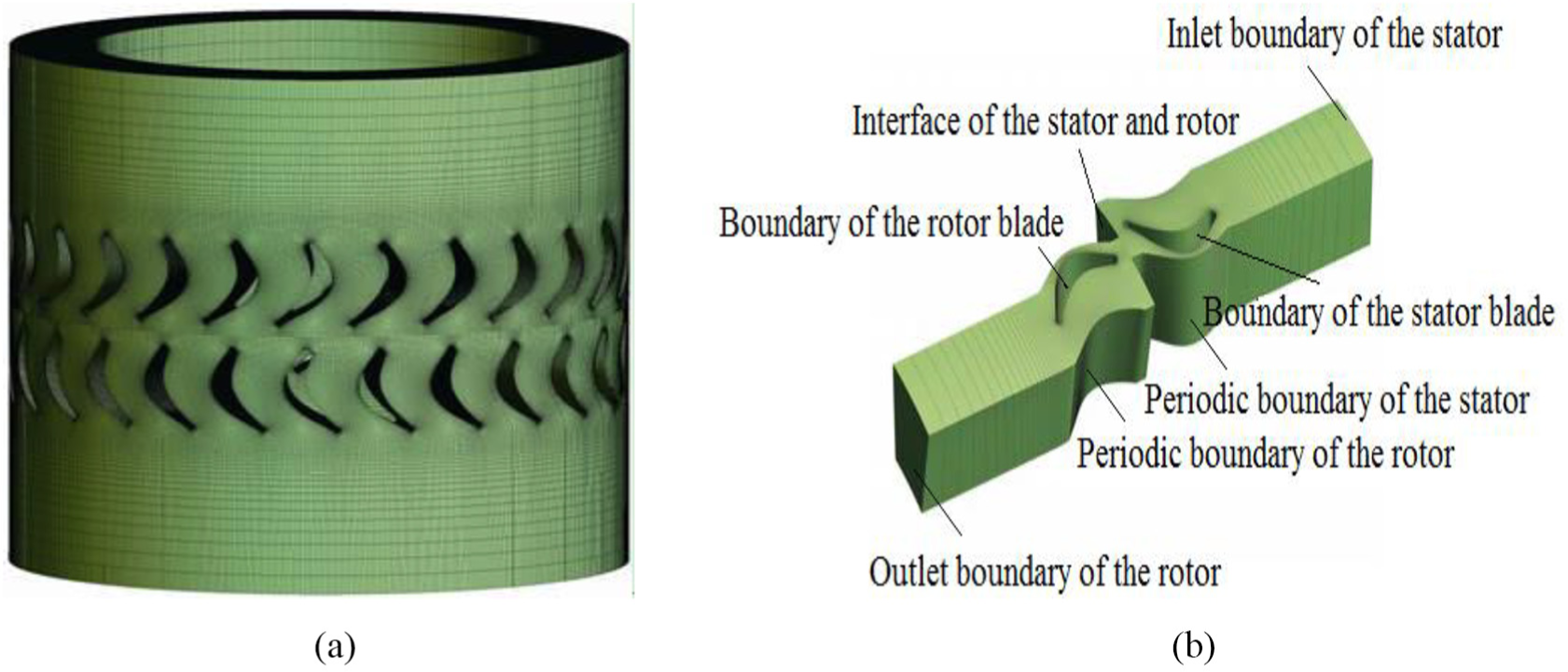
The 3D model of blade: (a) mesh diagram of turbine inner flow across and (b) boundary model of flow across the blade.
In order to ensure the accuracy of numerical calculation, the mesh independence is required to be checked. In this article, increasing the whole mesh number is used to verify the mesh independence.
In Figure 5, when the number of meshes is greater than 550,000, torque, pressure drop, and efficiency value vary less, which shows that the mesh number has little influence on the calculation results. It can be assumed that 550,000 of the mesh number have reached the mesh independent. In this article, the number of meshes for each blade calculation area was set about 550,000, so the computational time about 15 min for single-stage turbine. However, the computational time about 150 min for 10-stage turbine. Absolute method was used to set up the mesh near the wall, which ensures that the Y+ of the mesh at the wall of the runner was less than 5, and the mesh number of each stage stator and rotor blade is similar.

The study of mesh independence.
The nonslip boundary and periodic boundary are adopted in CFX software. And the hub, shell, the front and edge of rotor blade, and the wall are set to periodic cycle. The analysis type was set steady state, and the interface type of stator and rotor was set Frozen Rotor because it is considered that the fluid is in a state of stability. The inlet and outlet types were mass flow and relative static pressure, respectively. Turbulence intension was defined as moderate. The Navier–Stokes momentum conservation equation based on
When the stator blade is working, the fluid pressure, temperature, volume, and so on will change, and the power output will not be produced. Therefore, only the output performance of the rotor blade is considered in the article. The WZ-115 turbine drill with better hydraulic efficiency and turbine performance was chosen as the research object, and its standard stagger angle
The state of the flow field is chaotic, and the desulphurization and the reflux are serious, which will seriously affect the output balance and stability of the turbine. So, the variable geometry technology was used in the article. In other words, by changing the stagger of last-stage blade and last three stages blade of 10-stage turbine drill, the output performance and the flow field of the turbine influenced by the stagger angle were investigated.
Research on the last blade of multistage turbine by variable geometry technology
The output performance and the change of flow field for the 10-stage turbine are studied by simulating the working conditions of 10 stages’ blade based on variable geometry technology. Where the 1–9 rotors are the turbine blade with the standard stagger angle, the tenth rotor is the variable geometry blade, and the simulation range for the stagger angle is

The output power of

The outlet torque of
In Figures 6 and 7, with increase in the stagger angle of the last-stage blade, the output power and torque are slightly higher than the output power at standard stagger angle from R1 to R9, and the closer to the final stage, the greater the power and torque increase. With the increase in the stagger angle, the output power and torque of the last-stage blade (R10) decrease significantly. And the larger the stagger angle is, the more obvious the output performance decline of final stage. When the stagger angle is
Figure 8 is the velocity contour of the last-stage blade whose stagger angle is, respectively,
The velocity simulation of last-stage blade of 10-stage turbine: (a)
It can be seen from Figure 8 that with the increase in the stagger angle, the size of the flow separation area decreases, and the outlet velocity can be controlled. When the stagger angle is
Although the increase in the blade stagger angle is helpful for output performance of last stage and optimizes flow morphology, the output performance of eighth stage and ninth stage has not been improved. And compared with the output performance of the first stage to the seventh stage, the output power and torque of ninth stage and eighth stage are too large to balance the output of all stages. In order to improve the output performance of multistage gas turbine, it is necessary to change the stagger angle of the multistage blade.
Study on last three stages’ blades of multistage turbine by variable geometry technology
In this section, the variable geometry of last three blades for 10-stage turbine was studied. In other words, the output performance of turbine will be studied by changing the stagger angle of the blades from the eighth-stage blades to the tenth-stage blades. The stagger angle of the first seven blades is the standard stagger angle. From the eighth-stage blades to the tenth-stage blades, the stagger angle of the blade increases gradually, and the amplitude of increase between the adjacent two stages is
The parameters of stagger angle of blade.

The variation of output power and torque for last three stages’ blades at 10-stage turbine is, respectively, shown in Figures 9 and 10. The output power and torque are taken as reference when the stagger angle of all stages’ blade is standard stagger angle.

The outlet power of blade.

The outlet torque of blade.
As can be seen from Figures 9 and 10, with the increase in blade stagger angle of last three stages, the output power and torque of all stages tend to equalization from the A group to the D group. When the stagger angle of last three stages is, respectively, 50°, 51°, and 52° (D group), the differences of output power and torque of seventh and eighth stage are small. The change makes the output performance at all levels more average, and the difference is smaller comparing with 10 stages blades under standard stagger angle. In particular, there is not sudden change for output power and torque between the standard stagger angle and other stagger angle.
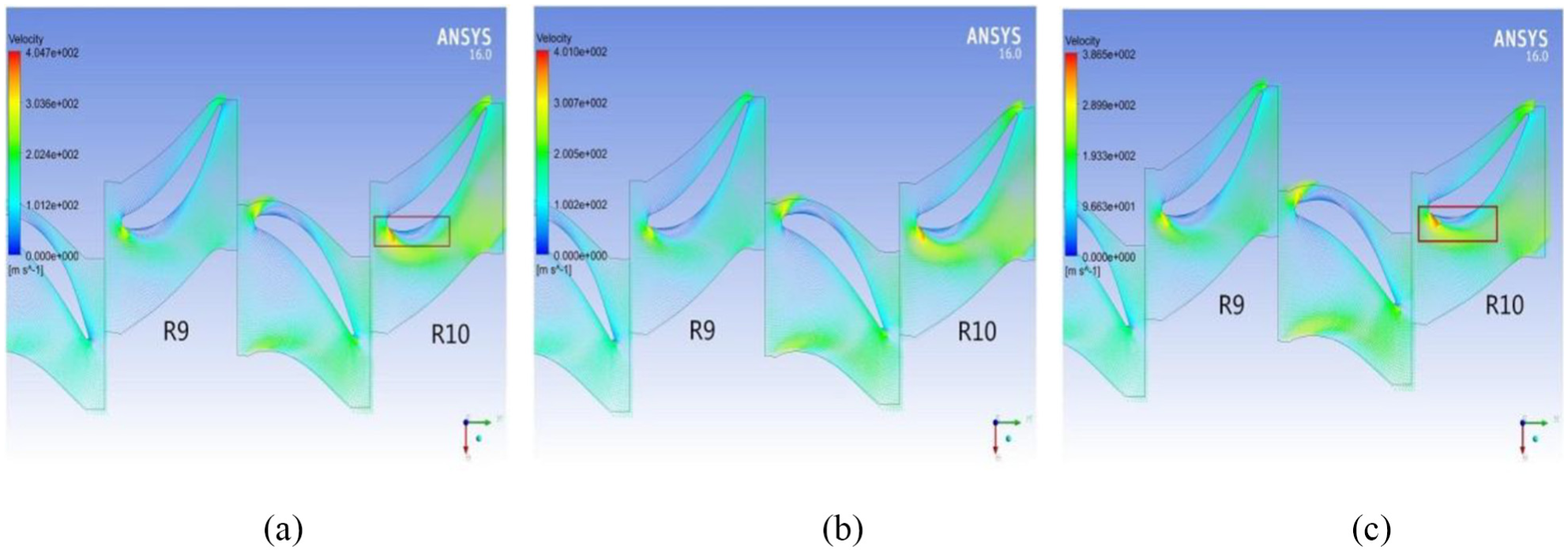
Figure 11 is the velocity contour of ninth and tenth stages for A–D group.

Velocity contour of A–D.
As can be seen from Figure 11, in A group, there is the phenomena of flow separation in the back of ninth- and tenth-stage blades; however, with the increase in the stagger angle, the phenomenon of flow separation is improved gradually. In the B group, the flow separation of ninth-stage blades is basically controlled. In the D group, there is not the phenomenon of flow separation for the ninth and tenth stages, and flow flied becomes stable.
Effect of variable geometry technology on aerodynamic efficiency
Based on the basic principle of the pneumatic power and the simulation software, the overall efficiency of the gas turbine was studied.
As is shown in Figure 12(a) is the aerodynamic efficiency of the last-stage blade after variable geometry for 10-stage turbine, where the first nine blades are standard stagger angle. With the increase in the blade stagger angle, the aerodynamic efficiency increases. When blade stagger angle is the standard stagger angle, the aerodynamic efficiency is 33.61%. When the stagger angle of the last-stage blades increases to 52°, the aerodynamic efficiency of turbine increases to 37.33%, which has added about 3.72% compared with that of the blades with the standard stagger angle. The aerodynamic efficiency of the last three stages’ blades after variable geometry for 10-stage turbine is shown in Figure 12(b), where the first seven blades are standard stagger angle. When the stagger angle of last three stages’ blades was set according to Table 1, the aerodynamic efficiency increased with the increase in the stagger angle. While the stagger angle was the data of the A group, the aerodynamic efficiency of turbine rose to 34.33%. If the stagger angle was set to the D group data, the aerodynamic efficiency of turbine rose to 38.49%, which increased by 4.88% compared to the aerodynamic efficiency of blade at standard stagger angle.
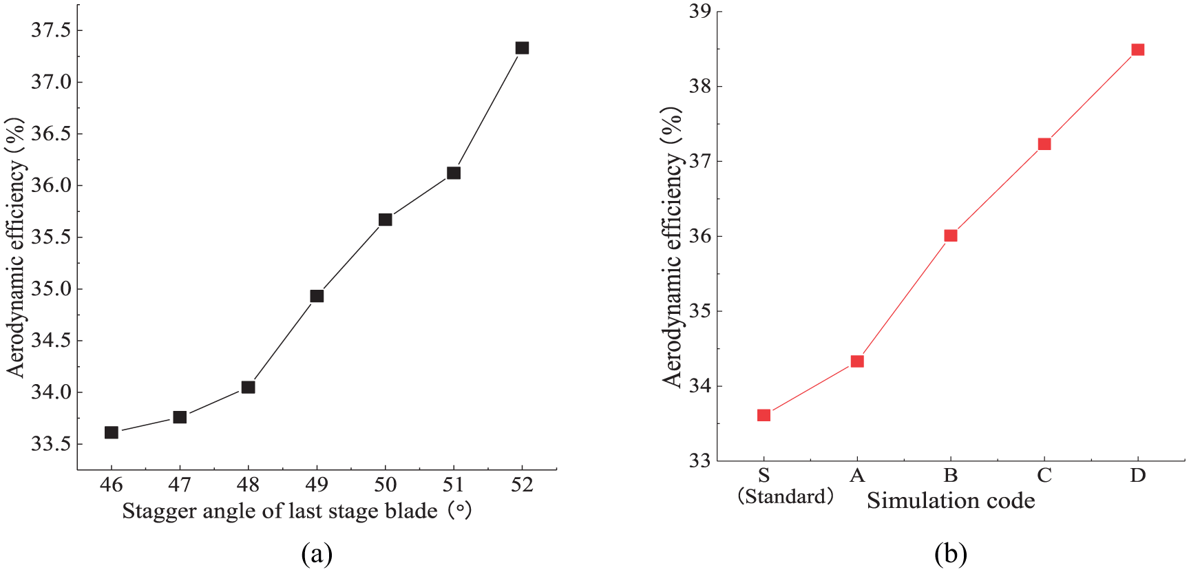
Aerodynamic efficiency of multistage turbine: (a) by changing last-stage blade and (b) by changing last three stages’ blades.
Based on the analysis above, if the variable geometry is further study on all stages blade of gas turbine drill, output power and torque of all stages will be more average. The flow field will also be improved and the aerodynamic efficiency of the turbine will be further improved.
Conclusion
Variable geometry technology was used to study the output performance of the last-stage blade and the last three stages blade for 10-stage turbine drill. The conclusions are as follows:
With the increase in the stagger angle of the last-stage blade, the output power and torque of the last-stage blade gradually decreased. When stagger angle of the last-stage blade is
With the increase in the stagger angle of the last-stage blade, the aerodynamic efficiency increases. However, the output power and torque of eighth stage and ninth stage have not been improved, which cannot be more uniform for the output power and torque at all stages.
With the increase in the stagger angle of the last three stages blades, the output power and torque for all stages tend to average, which can better balance the output torque and power at all stages. The aerodynamic efficiency is increased by 4.88%, and the results show that the variable geometry technology is also suitable for the multistage turbine.
Footnotes
Handling Editor: Assunta Andreozzi
Declaration of conflicting interests
The author(s) declared no potential conflicts of interest with respect to the research, authorship, and/or publication of this article.
Funding
The author(s) received no financial support for the research, authorship, and/or publication of this article.