
Abstract
Influence of impeller arrangement on performance, radial force, and pressure fluctuation for a double-suction centrifugal pump is investigated. In comparison of the original impeller with staggered angle α of 0°, the maximum improvement of pump efficiency is 2.19% for impeller with α of 30°, and the maximum improvement of pump head is 1.76% for impeller with α of 20°. The radial force vector on impeller is related to the staggered angle, and the phase angle of radial force vector is equal to the staggered angle. The staggered arrangement can effectively reduce the amplitude of radial force fluctuation. In comparison of case 0, the maximum amplitude of radial force fluctuation for case 30 reduces by 15.8%. The dominant frequencies of the radial force fluctuation for α = 0°, 10°, and 20° are fBP, while the dominant frequency for α = 30° is 2fBP. An empirical formula is proposed to predict the radial fluctuation amplitude at specific staggered angle. For a point of the volute far from the exit volute, in comparison of case 0, the maximum amplitudes of pressure fluctuation for case 10, case 20, and case 30 are reduced by 13.1%, 49.8%, and 93.3%.
Introduction
Complex flow in centrifugal pumps involving secondary flow and reverse flow and the fluid-dynamic blades–tongue interaction is proved to be a main factor for the flow instability for single-suction centrifugal pump.1–3 As a result, the operation of centrifugal pumps can result in the generation of unsteady radial forces and pressure pulsations,4,5 which can affect the mechanical integrity of the pump, resulting in intense vibration and noise.6,7
The radial force in pumps is inherently unsteady caused by the impulse of blades during rotating. Numerous works investigate the characteristics of radial force theoretically, experimentally and numerically.8,9 Guo and Okamoto 10 measured the radial force on impellers, pressure fluctuations in volute and vibration of the shaft experimentally and analyzed their relationship under the rotor–stator interaction. Kyung et al. 11 analyzed the velocity and the pressure field of a double-suction centrifugal pump using impeller-only model and a full pump model at rated condition and off-design condition. The velocity and the pressure variations at the inlet and outlet of the impeller were investigated. Hao et al. 12 investigated the performance and radial force with symmetrical and unsymmetrical tip clearance of a mixed flow pump. The magnitude of the radial force of the unsymmetrical tip clearance is approximately 15 times that of the symmetrical tip clearance.
Double-suction pumps are used in situation where high flow is required in a single-stage pump. Due to the two twin impellers, double-suction pumps have the advantage of zero average axial force according to their geometry. However, due to the high energies involved, double suction and double volute, these pumps usually suffer more from pressure pulsations than single-entry pumps.13,14 González et al. 15 analyzed the detailed flow field using numerical method to discuss the possibilities and drawbacks of the design. The unsteadiness of inlet flow of the impeller and the volute are studied by both the instantaneous and average pressure. The radial forces on the shaft have been calculated. Fernández et al. 16 investigated the influence of inlet nonuniformities through characteristics of the flow patterns of different geometries of the tongue. The features of jet-wake structure are analyzed by the blade-to-blade gradients in the impeller. The nonlinear interaction between the impeller and the volute tongue can be identified and quantified through a pure unsteady velocity component. Yao et al. 17 investigate the effects of impeller types on pressure fluctuations for double-suction centrifugal pumps experimentally. Results show that blade passing frequency, rotating frequency, and some lower frequencies always exist in double-suction centrifugal pumps. The double-suction impeller with staggered blades can reduce the level of pressure fluctuation. The impeller with splitter blades lessens the pressure fluctuation in suction chamber region and optimizes the pressure fluctuations in the spiral casing under rated flow rate. Zou et al. 18 investigated the impeller radial force in a double-suction centrifugal pump during startup at the shut-off condition. The radial force revolution was obtained during startup. The maximum radial force value was approximately nine times as high as that under rated condition. A transient radial force formula was proposed to predict the changes in radial force during startup.
In double-suction pumps, two impellers are arranged together. The geometry and flow pattern are quite different from other centrifugal pumps. Fluids from the two impellers are mixed at the volute inlet, which affects the static pressure distribution in the impeller and results in different force distribution. The impeller arrangements will influence the pressure distribution in volute. The detailed study of the mechanism of these phenomena is few. In this study, four double-suction impellers with different arrangements are investigated, and the influence of impeller arrangements on performance, radial force, and pressure fluctuation is investigated.
Physical model and computational domain
Geometry and working conditions of centrifugal pump
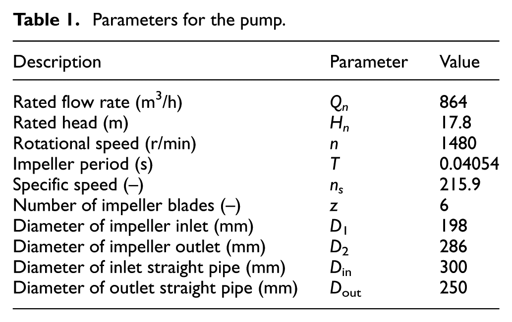
The investigated pump is a large double-suction centrifugal pump. Figure 1 shows the picture of the pump during experimental measurement. The pump has two twin impellers built together, as shown in Figure 1, with inlet diameter of 0.198 m, outlet diameter of 0.286 m and six blades. The main design parameters of the double-suction pump are summarized in Table 1. The specific speed is computed as

where Q′ is the flow rate in one impeller.

Tested double-suction centrifugal pump.
Parameters for the pump.
The entire flow domain in the geometric model includes the inlet straight pipe, double entry, two twin impellers, double volute, and outlet straight pipe, as shown in Figure 2(a). The staggered angle α, which is the angle between the two impellers, is also defined in Figure 2(b). Four different impeller arrangements are studied in this article, including an inline arrangement (α = 0°), a specific position staggered arrangement (α = 10°), a specific position staggered arrangement (α = 20°), and a middle position staggered arrangement (α = 30°), named as case 0, case 10, case 20, and case 30. For all cases, the position of impeller1 remains unchanged, while the impeller 2 is rotated with the staggered angle α.
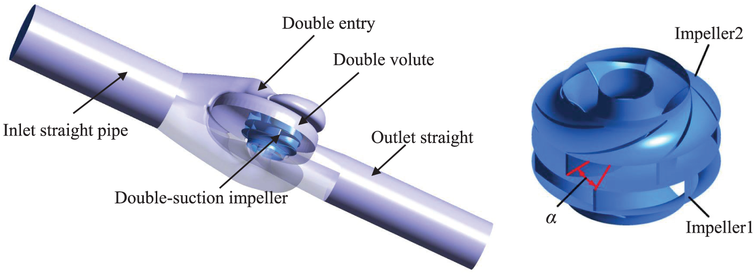
The geometry of the centrifugal pump: (a) the computational domain and (b) staggered angle.
Computational mesh of centrifugal pump
A three-dimensional model is established for the test pump and then discretized into a mesh. The impeller structured mesh is generated using CFX-TurboGrid. The volute and suction unstructured meshes are generated using ICEM, which are refined near the tongue region individually. Mesh quality is evaluated by the minimum face angle (≥25.139° in impeller) and maximum face angle (≤156.737° in impeller). The meshes of impeller, suction, and volute are shown in Figure 3.
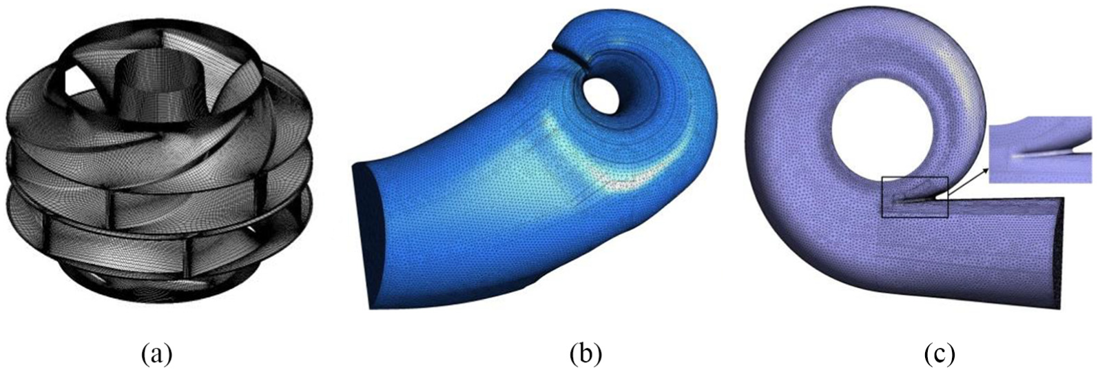
Mesh of different parts in pump: (a) impeller mesh of case 30, (b) suction mesh, and (c) volute mesh.
Numerical method and validation
Numerical simulation of the double-suction pump is conducted by solving the Reynolds-Averaged Navier–Stokes equations with ANSYS CFX with the re-normalization group (RNG) k–ε model. This method can accurately predict the rotating and curvature flow in the flow passage components, which is verified by a large amount of previous work.1,2,19 The working fluid is water. This work is conducted using total pressure at inlet and a mass flow at outlet as the set of boundary conditions, and no slip wall is applied at walls. The interfaces between rotating and stationary frames are modeled using the frozen-rotor and transient-rotor and stator interface options for steady and unsteady calculations, respectively. The steady state is taken as the initial flow field of the unsteady simulation. The convergence criterion is defined as that the root-mean-square residual for each equation at the end of each time step is below 1 × 10–5.20–22
Five sets of meshes with elements from 3,436,239 to 5,405,583 are employed to validate the grid independence, as shown in Table 2. The test results in Table 3 reveal that the variation in pump head ΔH/H1 and efficiency Δη/η1 is slight (less than 0.002). Considering computational cost and accuracy, Mesh 3 with 4,398,195 elements is selected as the final mesh in the following calculations.
Mesh sizes for mesh independency test.

The variation of pump head H/H1 and efficiency η/η1.

The time step for transient calculation is 2.1115 × 10⁻⁴ s, as this provided 192 time steps per impeller revolution of
Results and discussion
Performance curves
The test apparatus is established as a close-loop water circulation, including the tested double-suction pump and a set of digital equipment. The flow rate is measured by a split intelligent electromagnetic flowmeter (LDG-500s; Guanghua Instrument Co., Ltd, Shanghai, China), the head is tested by smart differential pressure transmitter (V15712-HD1A1D7D; Newsruipu Instrument Co., Ltd., Zhengzhou, China), and the rotational speed and torque are measured by the intelligent torque speed sensor (JCZL2-500; Powerlink Instrument Co., Ltd, Changsha, China). On analysis of the system uncertainty, the comprehensive error of pump performance measurement is estimated to be within ±0.3%. The staggered angle of the impeller for the tested pump is 30°. A comparison of the computational fluid dynamics (CFD) predictions with the experiments’ measurements of efficiency is shown in Figure 4 at eight flow rates. There is a general good agreement between the measurements and the prediction efficiencies, with the relative difference in efficiency at design flow rate below 2%. At off-design conditions, the relative errors of efficiencies are still below 5%, and the increase in error may be attributed to strong recirculation, complex backflow, and unsteady pressure fluctuation. 22 For pump head, a good agreement is reached at low flow rate, while the relative difference increases at large flow rate. The reason is that the impact on impeller inlet increases as the increase in flow rate, which induces the flow separation and vortex development in the impeller. Above analysis validates the accuracy and reliability of the numerical method.

Comparison of pump performance curves between experiment and calculation results.
Then, the performance of pumps for different cases is investigated using the validated numeral model. Table 4 lists the efficiency and head for different cases. As shown in the Table 4, the efficiency and head for four different impeller arrangements have a noticeable difference. The efficiency for case 30 is evidently greater than all other cases, especially under low flow rate. One possible reason is that at low flow rate, the second flow is responsible for the significant efficiency, but it gets partly offset for staggered arrangements. The offset effect enhances when the staggered angle increases from 0° to 30°. Besides, the head of case 0 is the lowest at all flow rates among all cases, while the head of case 30 remains the highest value from 0.8Qn to 1.2Qn. Therefore, the mid-position staggered arrangement of α = 30° presents an optimal overall performance. The maximum difference is 2.19% of efficiency between case 0 and case 30 at 0.5Qn and 1.76% of head between case 0 and case 20 at 0.5Qn. The difference is more obvious at low flow rates. This is mainly because that the outlet pressure at the same position from different impellers is different for case 10–case 30, which will cause the mixture of the fluid in the volute and affect the performance curves of the pump. A detailed study of this phenomenon is given below.
Efficiency and head for different arrangements at different flow rates.

Radial force vector
In the present research, transient results of the 11th revolution after 10 revolutions are considered to analyze the radial force in the pump. The magnitude of the radial force is computed at each time step by means of a full integration of the pressure and shear stress on surfaces of impeller. The radial force vectors are the vector sum of the two twin impellers. The polar coordinate system is established to show the radial force vector.
Figure 5 shows the radial force vectors on the two twin impellers and axis for different cases at different flow rates. As can be seen, the radial force vectors on impellers are a closed curve, appearing as a hexagram at 0.8Qn and 1.2Qn, and a rough circle at 1.0Qn for all cases, so as that on axis. Meanwhile, the average radial force on impellers changes at different flow rates, with the smallest at 1.2Qn and highest at 0.8Qn. This is because that the radial force on impellers of working pump mainly originates from the working fluid.

The instantaneous radial force vectors on impeller and axis for different cases at different flow rates: (a) radial force vectors on impeller at 0.8Qn, (b) radial force vectors on axis at 0.8Qn, (c) radial force vectors on impeller at 1.0Qn, (d) radial force vectors on axis at 1.0Qn, (e) radial force vectors on impeller at 1.2Qn, and (f) radial force vectors on axis at 1.2Qn.
As shown in Figure 5, the fluctuation of radial force on axis is different for different staggered angles. The fluctuation is the strongest for case 0, followed by case 10 and case 20, and the weakest for case30. The phenomenon is evident at 0.8Qn and 1.2Qn. At 1.0Qn, the radial force fluctuations of radial force are small and hard to notice the difference for different cases. There is also an offset effect exists between the staggered impellers. As the phase difference of the radial force fluctuation of the two impellers increases, the radial force pulsation on the principal axial gets more weakened due to the increase in offset effect between the two twin impellers.
Except for evident difference of radial force vectors on axis, a relative small difference is shown on the two twin impellers for different cases. As shown in Figure 6, to further investigate the radial force difference on impellers for different cases, the radial force vectors on the impellers for different cases are plotted individually at 0.8Qn. For one case, the amplitude and period of radial force fluctuation of the two impellers are the same. The phase angle β of the radial force on impeller 1 and impeller 2 is equal to the staggered angle α.

The instantaneous radial force vectors on the two twin impellers for different cases at 0.8Qn.
Table 5 lists the maximum amplitudes of radial force fluctuation on impeller 1 and impeller 2 for different cases. The amplitude values in Table 5 are obtained by the spectrum analysis of radial force for different impellers. The amplitude of radial force fluctuation on impeller 1 and impeller 2 is nearly the same at case 0, while there is a difference at case 10, case 20, and case 30 due to the circumferential asymmetrical structure. It is obvious that this staggered arrangement can effectively reduce the amplitude of radial force fluctuation. In comparison of case 0, the maximum amplitude of radial force fluctuation for case 30 reduces by 15.8%.
The maximum amplitudes of radial force fluctuation on impellers at 0.8Qn.

The differences in the radial force amplitudes are caused by the working fluid in the pumps, especially the mixture of the two impeller-outlet fluids in the volute inlet. To study the relationship between flow characters and the radial force fluctuation, a cross section of 180° from the tongue is selected, and the streamlines and pressure distribution for different cases are shown in Figure 7. A partial enlargement of the impeller outlet is shown on the right-hand side. For case 0, the flow pattern of two twin impellers is symmetrical, with symmetrical pressure distribution in volute and interaction line of the streamlines from the two impellers appearing as a straight line. Because the pressure distribution on the axial plane of impeller is uneven in the circumferential direction, as α increases from 10° to 30°, the static pressure difference of the adjacent fluids from two impellers increases, as shown in Figure 7(b)–(d). For case 10 and case 20, the outlet velocity of impeller 2 is larger than that of impeller 1, and the pressure of impeller 2 is smaller than that of impeller 1. As can be seen, a small radial flow is induced from the outlet of impeller 1 to impeller 2. For case 30, the outlet velocity of impeller 2 is much larger than impeller 1, and there is a radial flow generated from upper fluid to the lower fluid. The tiny perturbation between the two pressure zones mixes the fluid in same pressure. In this way, the pressure in higher pressure zone decreases, while the pressure in lower pressure zone increases. This change will affect the pressure distribution in impeller and make the radial force of different staggered angles different.
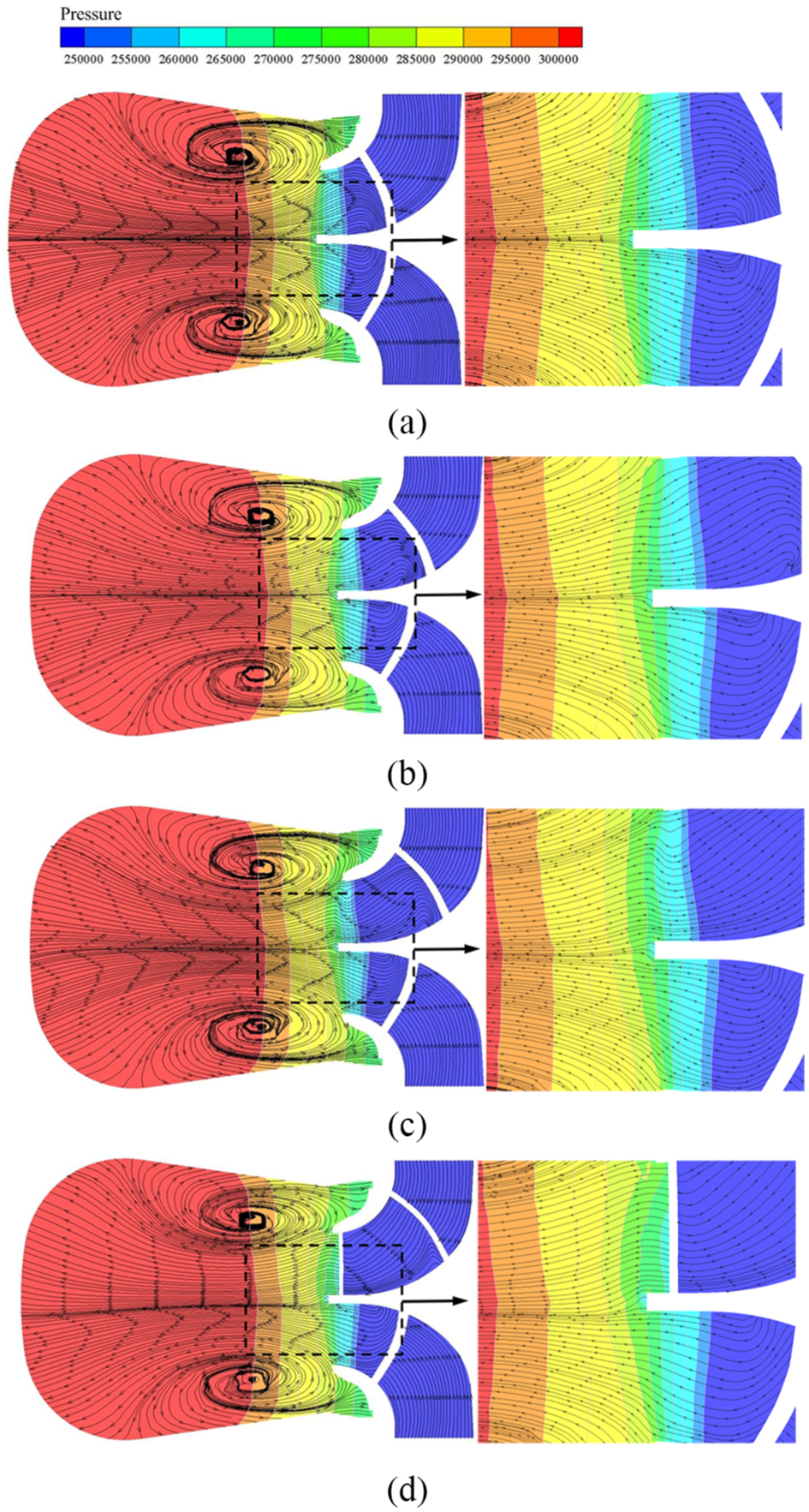
The instantaneous velocity streamline and pressure distribution near impeller outlet for different cases: (a) case 0, (b) case 10, (c) case 20, and (d) case 30.
Frequency domain analysis for the radial force
A fast Fourier transform (FFT) is presented to investigate the dominant frequency and corresponding amplitude of radial force. Figure 8 shows the spectrum analysis of radial force for different cases at 0.8Qn, 1.0Qn, and 1.2Qn. Table 6 shows the dominant frequencies and maximum amplitudes of radial force for different staggered angles at different flow rates. As shown from Figure 8 and Table 6, the dominant frequencies of the radial force for case 0, case 10, and case 20 are the blades’ passing frequency fBP = (n × z)/60 = 148 Hz. The amplitudes decrease from case 0 to case 20 at all flow rates. For case 30, the radial force amplitudes at fBP are eliminated at all flow rates, which is due to the offset effect at this frequency. The time required for the impeller to rotate by 60° is 1/6 × T and the corresponding frequency is fBP. For case 30, the staggered angle between the two impellers is 30°, which is half the radial force fluctuations period at fBP. As a result, the radial force of the two impellers with staggered angle of 30° will counteract each other. However, the staggered angle is equal to the rotation angle of 1/12T, which is the radial force fluctuation period at 2fBP, and then, there is a superimposed effect of the two impellers for radial force fluctuations at 2fBP during rotation. Therefore, the amplitudes at 2fBP are intensified.

Spectrum analysis of radial force at different flow rates: (a) 0.8Qn, (b) 1.0Qn, and (c) 1.2Qn.
The dominant frequencies and maximum amplitudes of radial force for different cases at different flow rates.

Figure 8 shows that the variation trend of force amplitudes at different flow rates appears similar. Thus, in order to obtain the fluctuation variation of the pump at different flow rates, the radial force fluctuation
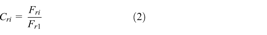
where Fri (i = 1, 2, 3, 4) is the amplitudes of radial force fluctuation at fBP for case 0, case 10, case 20, and case 30 individually at a certain flow rate. For example, Fr1 is the amplitudes of radial force fluctuation at fBP for case 0 at a certain flow rate. Figure 9 shows the evolution of radial force coefficient at different flow rates as the function of the staggered angle α. The change of

where Cr is the relative radial force coefficient at a certain flow rates and Ra = α/60 is the relative angle coefficient. The residual sum of squares of polynomials and curves is 8.21 × e–4. It can be concluded that the relationship between the relative radial force coefficient Cr and staggered angle α is related to the structure of pump. Therefore, this formula can provide an empirical reference for specific staggered angle under different flow rates.
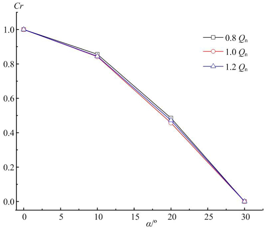
Evolution of radial force coefficient at fBP.
Flow pattern in volute
To investigate the relationship between radial force and flow field in volute, the pressure distributions in volute are studied for different cases. Figure 10 shows the instantaneous static pressure distribution at middle-span plane of volute at t = 0.92 s. The obvious effect of stagger arrangement can be observed in case 30 with the pressure distribution at middle-span plane is almost like a circle, because the staggered angle of the two impellers is 30°, which is half of the pressure contour period. The offset effect leads to more uniform pressure distribution near the volute inlet. While for case 0, the pressure contour is like a hexagram induced by the impeller and volute interaction. The results show that the pressure distribution at volute inlet is influenced by the two impellers. The shape of pressure contour near inlet of the volute for case 10 and case 20 is in the middle of case 0 and case 30.

The instantaneous static pressure distribution at mid-span of volute at 1.0Qn: (a) case 0, (b) case 10, (c) case 20, and (d) case 30.
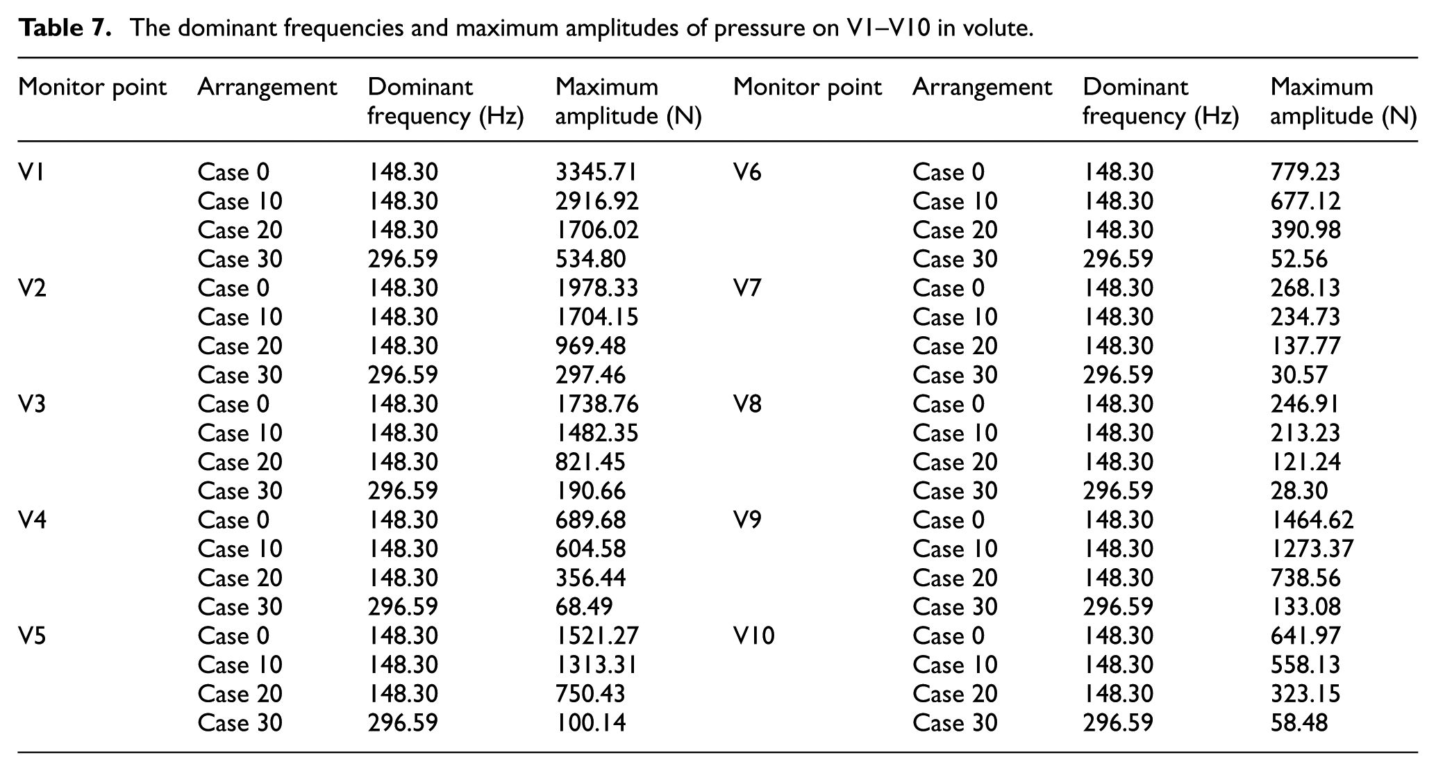
To investigate the pressure fluctuation in volute, 10 monitoring points V1–V10 on volute mid-span are set, as shown in Figure 11. The spectrum analysis of pressure fluctuation on V1–V10 for different cases at rated flow rate is shown in Figure 12, on behalf of different region in volute. The dominant frequencies of the pressure fluctuation in volute for case 0, case 10, and case 20 are the fBP, while the dominant frequency for case 30 is 2fBP. As can be seen, the frequencies’ variation trend of pressure fluctuation spectrum analysis in volute for different cases is similar to that of radial force. As a result of the rotor–stator interaction, the main frequency of pressure fluctuation induced by one impeller is multiples of fBP. The domain frequency of pressure in volute with single impeller is fBP, the period of which is equal to 1/6T. For case 0, the two impellers are symmetrical. The frequency is the same as that of one impeller, with the maximum amplitude of pressure fluctuation in volute for all impeller arrangements. When the staggered angle increases from 10° to 30°, the amplitude at fBP gradually reduces due to the offset effect between the two impellers. For case 30, the phase difference of the circumferential pressure distribution of the two twin impellers is 30°, corresponding to half a fluctuation period. As a result, the domain frequency shifts from fBP to 2fBP, while the amplitude at 2fBP reaches the peak value due to the superimposed effect. The dominant frequencies and maximum amplitudes of pressure on V1–V10 in volute at 1.0Qn is shown in Table 7. The amplitudes’ variation trend of pressure fluctuations for different cases is similar to that of radial force. The maximum amplitude reduction is about 13% for case 10, about 50% for case 20, and about 90% for case 30.

Monitoring points in volute at mid-span of centrifugal pump.

Spectrum analysis of pressure fluctuation in volute for different cases at 1.0Qn: (a) V1, (b) V2, (c) V3, (d) V4, (e) V5, (f) V6, (g) V7, (h) V8, (i) V9, and (j) V10.
The dominant frequencies and maximum amplitudes of pressure on V1–V10 in volute.
Conclusion
A numerical simulation of the entire double-suction centrifugal pump has been conducted, including the inlet straight pipe, double entry, two twin impellers, double volute, and outlet straight pipe. The performance curves obtained with the numerical model have been compared with experimental data to verify the accuracy of the numerical method. The impact of impeller arrangements on radial force of the double-suction centrifugal pump is investigated. The flow pattern and pressure fluctuation in volute with different impeller staggered angles are analyzed and compared. The main conclusions can be drawn as follows:
The influence of impeller arrangements on performance of the double-suction centrifugal pump is noticeable. In comparison to case 0, the maximum improvement of efficiency is 2.19% for case 30 at 0.5Qn, and the maximum improvement of head is 1.76% for case 20 at 0.5Qn.
The radial force vectors on impeller are closely related to the staggered angle, and the phase angle of the radial force vector is equal to the staggered angle. A radial flow from higher pressure to the lower pressure at impeller outlet is the reason of the difference in amplitude and phase of radial force for different staggered angles. The staggered arrangement can effectively reduce the amplitude of radial force fluctuation. In comparison to case 0, the maximum amplitude of radial force fluctuation for case 30 reduces by 15.8%.
Due to the offset effect at fBP and superposition effect at 2fBP of the two twin impellers, the dominant frequency of the radial force fluctuation for case 0, case 10, and case 20 is fBP, while the dominant frequency for case 30 is 2fBP.
The radial force pulsation is reduced at the same rate at different flow rates. An empirical formula is proposed to predict the radial fluctuation amplitude at specific staggered angle at different flow rates. This result shows that the proportion of the radial force pulsation reduction is related to the geometry of the twin impellers and independent of the flow rates.
The dominant frequency of the pressure fluctuation in volute for case 0, case 10, and case 20 are the fBP, while the dominant frequency for case 30 is 2fBP. For all the monitor points, compared with case 0, the maximum amplitudes’ reduction is about 13% for case 10, about 50% for case 20, and about 90% for case 30.
According to the research above, the differences in radial force and pressure fluctuation under different staggered angle have been observed. The suppression of pressure and radial force fluctuations is the primary contribution of the staggered impeller.
Footnotes
Handling Editor: Shun-Peng Zhu
Declaration of conflicting interests
The author(s) declared no potential conflicts of interest with respect to the research, authorship, and/or publication of this article.
Funding
The author(s) disclosed receipt of the following financial support for the research, authorship, and/or publication of this article: This work has been supported by the Tsinghua University Initiative Scientific Research Program (grant no. 20151080376), the National Natural Science Foundation of China (51741906), the Open Research Fund Program of State key Laboratory of Hydroscience and Engineering (sklhse-2018-E-01), the State Key Laboratory of Hydroscience and Engineering (2018-KY-02), and the Key Laboratory of Fluid and Power Machinery (Xihua University), Ministry of Education (szjj-2017-100-1-004).