
Abstract
Due to the introduction of multiple subsystems, it is very difficult for a hydraulic hybrid loader to improve its fuel economy with traditional braking control strategy and classic optimization algorithm. To deal with this problem, a combined braking control strategy based on fuzzy control system was proposed. In this strategy, the current working step and working cycle were first recognized with sensor signals. And the optimal control rules for different working cycles were optimized by genetic algorithm off line. After doing that, the obtained control rules were used to control the braking process and the energy distribution process of loaders. Simulation and experimental results show that the control strategy can make full use of the braking energy and can improve the recovery rate of it under the guarantee of safety and stability.
Introduction
As the energy and environment problem becomes more and more serious, hydraulic hybrid engineering vehicles are becoming an important way of technological innovation in automotive industry for its features on fuel economy and environmental protection.1–5 In the process of starting, speeding up, slowing down, and braking, hydraulic hybrid power system can stably charge/discharge energy at a higher power density. It makes engineering vehicles with such a system widely used.6–8 In particular, the recovered braking energy of accumulator can be used not only for electro-hydraulic braking but also for driving other systems or working devices in vehicles. It is conducive to saving energy, protecting environment, and satisfying various needs.
For hydraulic hybrid engineering vehicles, most of the present researchers are interested in improving the braking energy recovery rate and increasing its energy utilization.9–11 The logic threshold–based control strategy sets the values of initial parameters by engineering experience and adjusts them by combining the trial and error method.12,13 Although, with these strategies, the energy efficiency can be significantly improved, it is clear that they do not guarantee an optimal result in all situations. The reason lies in the fixed parameters set in the initial stages. The dynamic programming algorithm can find the global optimal solution of the control parameters.14,15 But it cannot give an online solution since it needs to know the entire process of a driving cycle. Fuzzy energy management strategy (EMS) controls the hybrid power train with fuzzy logic; it has good real-time performance and strong robustness.4,16 However, fuzzy logic and controller are designed by expertise. It cannot find the optimal solution. In fact, the performance of control strategy is largely decided by the driving conditions and the configuration of EMS. The optimal control strategy obtained in a special driving condition can hardly obtain the same performance in other different driving cycles.
For a loader, frequent lifting, lowering, acceleration, and deceleration are important characteristics. And the driving cycles of it are very different from traditional vehicles. An optimal control strategy or control method designed for a special hydraulic hybrid vehicle cannot be simply transplanted to different hydraulic hybrid loaders17–20 since the operation procedure and the working condition are very different. Thus, in this article, working cycle identification–based regenerative braking control strategy and power split control strategy were presented, in which the efficient flow and optimal split of energy within electric-hydraulic braking system, regenerative braking system, power split system, and other systems are synthetically considered. At the same time, the safety and stability of the braking system can be guaranteed. In order to study the changes of braking power split system and the energy recovery rate of the presented control strategy, a combined simulation model is established with MATLAB/Simulink. The proposed strategy was experimentally validated with a combined brake test bench, which was built with dSPACE real-time simulation system.
The combined braking system
For a traditional loader, the energy was seriously wasted in the lowering and braking processes.21–26 To make the regenerative braking system and electro-hydraulic braking system work in parallel, a secondary component was added to the drive shaft at the bottom of traditional loader. The two parts were connected together with a torque coupler. In this way, the energy recovered in the regenerative braking process can be used to charge the electro-hydraulic accumulator and to drive other subsystems.27,28 The combined braking system in hydraulic hybrid loader can be divided into three major subsystems: electro-hydraulic braking subsystem, power split subsystem, and regenerative braking subsystem. It can be seen in Figure 1.

Schematic of combined braking system.
Driving cycle identification
For a loader, the driving cycles of it are complex and changeable, which can be divided into running cycles and working cycles. For working cycles, the four commonest types of them are “I” type, “T” type, “V” type, and “L” type. This can be seen in Figure 2.
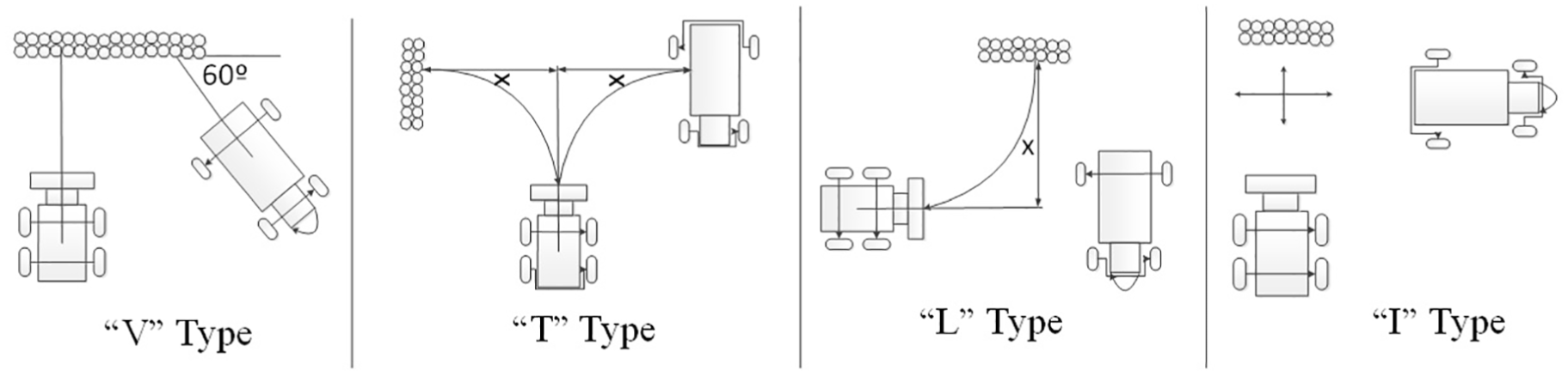
Working cycles of a loader.
The operating rules and control characteristics of the four working cycles can be described like this:
“V” type. The angle between the parked truck and the working surface is 60°. The driver has to adjust the running direction continuously after the bucket was filled up and uninstalled. Comparing with other working cycles, the running time of it is short and its working efficiency is higher.
“T” type. The parked truck is static and parallels to the working surface. Loader shuttles back and forth, between the working surface and truck. Due to its high energy consumption and complexity of operation, this working cycle was selected only when the workplace or parking position of the truck was limited.
“L” type. The dump truck is perpendicular to the working surface. The loader drives in reciprocating motion of 90° range from the working surface. In this type of working cycle, two trucks can be simultaneously loaded and the transport interval/parking time of the loader can be saved.
“I” type. The reciprocating motion of the loader is perpendicular to the working surface and the dump truck is parallel to the working surface. The operation of the loader is simple, and the number of braking is the least. But its comprehensive energy consumption is higher and the overall working time is longer.
The proposed fuzzy braking control strategy
The structure and principle of the fuzzy controller proposed in this article are shown in Figure 3. The braking torque is determined according to the opening degree of the pedal during the braking process. The proportion of regenerative braking torque (RBT) and electro-hydraulic brake torque is decided according to the parameters, state of charge (SOC), and velocity. On the premise of safety, the maximum RBT is used, and the insufficient braking torque is provided by the electro-hydraulic braking system. In the braking process, the SOC of the regenerative braking accumulator, the vehicle speed (V), and the braking intensity (Z) were fed back to the fuzzy controller. In this way, RBT and electro-hydraulic braking torque (EHBT) can be adjusted in real time, so as to the better energy saving effect can be reached.
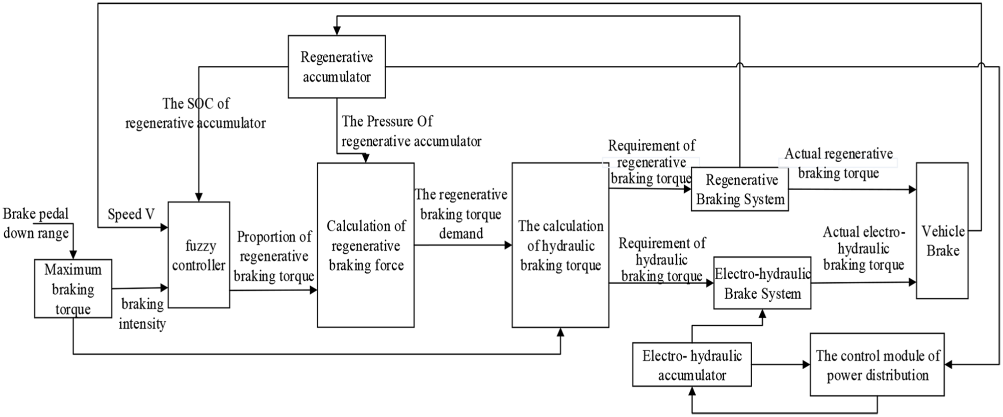
The principle of the fuzzy control strategy.
The adaptability and robustness of fuzzy control technique make itself an attractive alternative to classical control strategies in the distribution process of braking torque. However, for a fuzzy controller, it is very difficult to effectively distribute the braking and driving torque in different working cycles with only one set of fixed parameters or rules. Thus, in this article, the types of the working cycles were first identified by velocity or other parameters. And then, the membership functions were optimized with genetic algorithm. It can be seen in Figure 4, where the parameters of the fuzzy controller were determined for each working cycle.

Fuzzy controller based on GA.
For a fuzzy controller, deciding membership functions and fuzzy control rules by experts will not guarantee an optimal solution. Subjective and fixed control parameters cannot deal with different working cycles. The nonlinearity of fuzzy control calls for stochastic global optimization approaches. Thus, evolutionary algorithm (EA) was used to optimize the membership functions and fuzzy control rules. The code of the membership functions and fuzzy control rules were shown in Figures 5 and 6. These membership sets are symmetrical about the center of the domain and the membership function parameters were decided by real numbers x1, x2, y1, y2, z1, z2, t1, t2, t3, t4. The coordinates of the triangles were ascertained by these real numbers, which will be optimized by EAs. Thus, a total of 10 membership function parameters should be determined. The fuzzy control rules can be seen as the combination of a group of fuzzy sets of input and output variables. As the fuzzy sets of input variables are decided, the consequent part of these rules will be given.
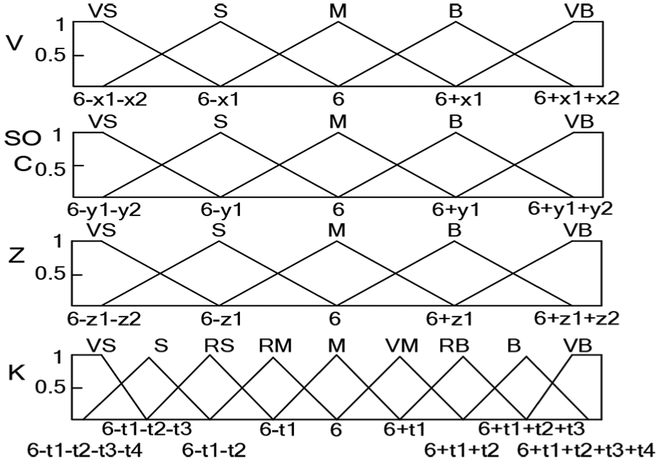
Optimized parameters of the membership function.

Individual code.
The code of each individual is shown in Figure 6. The fuel consumption was seen as the optimized objective, and a total of five groups of membership functions and control rules were obtained by the EA algorithm (four groups for working cycle, one group for running cycle). In the optimizing process, the EA algorithm kept on modifying the optimized variables and calling for the ADVISOR simulation to simulate the five groups of working/running cycle. The fuel consumption was seen as fitness function. After the optimization for five groups of working/running cycles, the fuzzy torque distribution controller can find an optimal strategy for each of them. Having completed the optimization process, the controller can start to work in a real working environment.
In fact, for a hydraulic hybrid loader, the obtained recovering energy can be used not only for charging the electro-hydraulic braking system but also for driving the vehicle or its components. In this article, pressure ranges of regenerative accumulator and electro-hydraulic accumulator were 15–25 MPa and 7.5–14.5 MPa. When the pressure of electric-hydraulic accumulator is lower than its minimum working pressure, the regenerative braking energy storage device will fill liquid for it. If the pressure of regenerative accumulator reaches its minimum working pressure, a steering pump device will replace it to fill liquid for the electric-hydraulic accumulator.
System modeling
The hydraulic hybrid system is divided into three parts, which are electro-hydraulic braking system, regenerative braking system, and power control system. Regenerative braking system consists of variable cylinder, plunger type variable pump/motor, and regeneration energy storage sub-system. Power distribution system consists of three solenoid valves and power distribution module. With the following formula, the mathematical model of each module can be established.
Solenoid directional valve
When the solenoid directional valve is opened, the equation of the valve core can be expressed as

When the solenoid valve is closed, the motion equation of valve core can be expressed by

where m is the quality of the valve core, x is the spool displacement, Ki is the electromagnet’s current-force gain, I is the current, Bv is the viscosity damper coefficient of the valve core, Bt is the transient hydrodynamic coefficient, Ks is the steady hydrodynamic coefficient, K is the spring stiffness, and x0 is the spring precompression.
When the solenoid directional valve is opened, the flow of it can be expressed by

where Cd is the flow coefficient, A1 is the flow area, ρ is the density of the liquid, pv is the inlet pressure of the solenoid directional valve, and
Without consideration of the compressibility of oil fluid, the flow continuity equation in the process of power distribution system is

Considering the pressure loss in the system
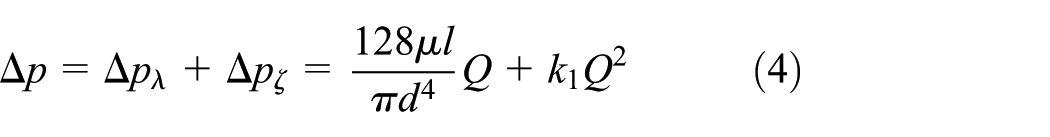
where Δpλ is the pressure loss along the way, Δpζ is the local pressure loss, μ is absolute viscosity, l is the length of a pipe, d is the diameter of the pipe, Q is the flow through the pipe, and K1 is the proportion factor.
Variable cylinder
The force balance equation of the piston is

The flow equation is

where A2 is the effective end surface area, M2 is the equivalent mass of the piston and accessories, B2 is the viscous damping of the piston, k is the spring stiffness, y is the displacement of the push rod, V is the effective volume, and β is the equivalent volume of the elastic modulus.
Pump/motor
The displacement expression of the pump/motor is

The expression of the RBT is

The flow expression of the pump/motor is

where V is the displacement of the variable pump/motor, d is the diameter of the plunger, Z is the number of the plunger, D is the diameter of distribution circle, y is the piston displacement of the variable cylinder, λ is the displacement gain of the swash plate angle and variable cylinder piston, and p is the outlet pressure of the hydraulic pump/motor.
Regenerative accumulator

where p0 is the inflation pressure of the regenerative accumulator; V0 is the effective volume of the regenerative accumulator; n is the variable process index of gas, n = 1.4; p is the outlet pressure of the regenerative accumulator; and C1 is the liquid filled liquid volume of the regenerative accumulator.
Simulation
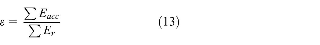
The simulation model of the combined braking system was established with MATLAB/Simulink. From Figure 7, it can be seen that the model was composed of an electro-hydraulic braking system, a regenerative braking system, a hydraulic driving system, and a vehicle dynamics model. To clearly illustrate the energy recovery and utilization effect, the parameters of energy recovery rate and hydraulic energy were used to evaluate the effect of energy recovery.
Vehicle’s kinetic energy is
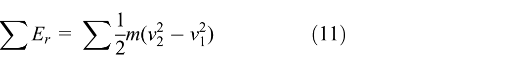
The energy of hydraulic accumulator is

The efficiency of energy recovery is
where m is the total mass of the vehicle; v2 is the terminal velocity of the vehicle; v1 is the vehicle’s initial velocity; V2 is the terminal gas volume of the regenerative accumulator; V1 is the initial gas volume of the regenerative accumulator; p1 is the initial pressure of the regenerative accumulator; and β is the polytropic exponent, β = 1.4.
The simulation model.
Comparisons on different initial velocities
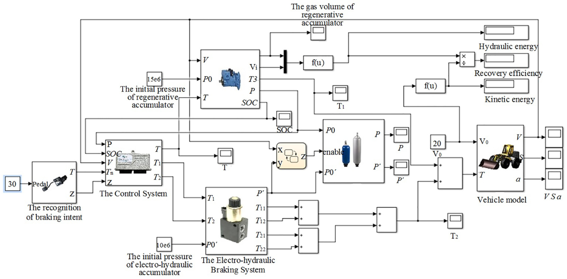
In this section, the down amplitude of the driver’s brake pedal was set to 30%; the initial pressure of the regenerative accumulator and electro-hydraulic accumulator were set to 15 and 10 MPa, respectively; and the total mass of the vehicle was 2500 kg. In the braking process, the distributions of braking torque at different initial velocities are shown in Figure 8. From it we can find that each of the braking torque is composed of RBT and EHBT. When the initial velocities were set to 10, 20, and 30 km/h, the regenerative torque first kept unchanged for almost 0, 1.5, and 2.5 s. And then, with the advance in braking, the regenerative torque gradually reduced to zero. To ensure the safety of braking, the insufficient part is filled with electro-hydraulic brake torque.
The distribution of regenerative braking torque and electro-hydraulic braking torque.
In Figure 9, the pressures of regenerative accumulator and electro-hydraulic accumulator were also shown. It can be seen that the higher the initial velocity of the vehicle, the greater the pressure of the regenerative accumulator changes and the longer time the electro-hydraulic braking process continues. In Figure 10, it can be seen that the greater the initial velocity, the more the hydraulic energy is recovered. When the initial velocity reaches a certain value, such as 20 or 30 km/h, the energy recovery efficiency is almost the same. When the initial velocity is very low, only rare energy is recovered.
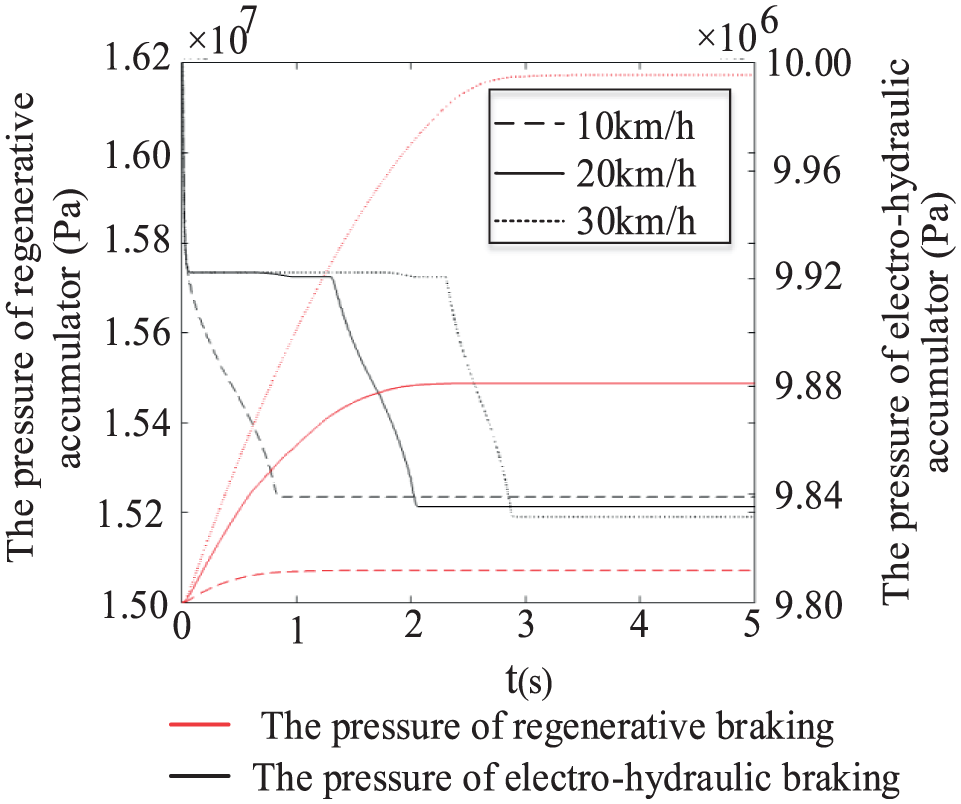
The pressure of the regenerative accumulator and electro-hydraulic accumulator.

The energy recovery efficiencies at different initial velocities.
Comparisons on different braking intensities
In this section, the initial velocity was set to 20 km/h; the initial pressure of the regenerative accumulator and electro-hydraulic accumulator were set to 15 and 10 MPa, respectively; the total mass of vehicle was set to 2500 kg; and the braking intensity was presented by down amplitude of the brake pedal. The distribution of the braking torque and the gas volume of the regenerative accumulator are shown in Figures 11 and 12. It can be seen that when the braking amplitude of the brake pedal is set to 10%, in a mild braking mode, the brake torque is provided mostly by the regenerative brake torque. Thus, the change in the gas volume is greater. When the brake pedal is set to 100%, in an emergency braking mode, the brake torque is provided just by the electro-hydraulic brake torque to ensure safety. In this condition, the value of the gas volume stays almost the same.

The distribution of braking torque at different braking intensities.
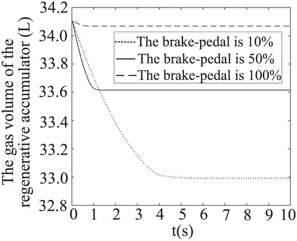
The gas volume of regenerative accumulator.
To clearly indicate the changing trend of energy recovery efficiency, the hydraulic energy and kinetic energy of the loader were presented with different amplitudes of the brake pedal. In Figure 13, it can be seen that the smaller the down amplitude of the driver’s brake pedal, the more the hydraulic energy of the regenerative braking system is recovered. At the same time, energy recovery efficiency keeps a high value. When the down amplitude of the driver’s brake pedal is 100%, in an emergency braking mode, the energy recovery efficiency reaches its lowest value, 0.

The energy recovery at different braking intensities.
Comparisons on different initial pressures
In this section, the initial braking velocity was set to 20 km/h, the down amplitude of the driver’s brake pedal was set to 30%, the initial pressure of the electro-hydraulic accumulator was set to 10 MPa, and the total mass of the vehicle was 2500 kg. In Figures 14 and 15, it can be seen that when the initial pressure of the regenerative accumulator is close to the upper limit of working pressure, only little RBT is acted. And the fluctuation of it was slight. With the decrease in the initial pressure, the change in the SOC of the regenerative accumulator is gradually increasing.

The distribution of braking torque at different initial pressures.

The SOC of the regenerative accumulator.
Figure 16 shows that the lower the initial pressure of regenerative accumulator, the more the hydraulic energy of the regenerative braking system is recovered and the higher the efficiency of the energy recovery. When the initial pressure of the regenerative accumulator is close to the maximum working pressure, the control strategy will give its judgment on whether or not to drive the loader or its components by more hydraulic energy.

The energy recovery at different pressures of the regenerative accumulator.
Comparisons on different control strategies
To compare the proposed fuzzy rule–based braking energy control strategy with traditional threshold value–based control strategy, the hydraulic energy, kinetic energy, and recovery efficiency of the two strategies for different working conditions are shown in sections “Comparisons on different initial velocities,”“Comparisons on different braking intensities,” and “Comparisons on different initial pressures.” From Table 1, it can be seen that, in most of the working conditions, the energy recovery efficiency of the proposed fuzzy rule–based control strategy was higher than that of the traditional threshold value–based control strategy. In fact, more safeguard strategies were taken into account in the proposed braking energy control strategy and that will lead to little loss of the braking energy. This can be seen in Row 1, where the recovery efficiency of the proposed strategy is somewhat less than that of the traditional threshold value–based control strategy.
Comparison on different control strategies.

Experiments
The test bench
To validate the working cycle recognition–based fuzzy EMS, a test bench was constructed. It consisted of a control system, a hydraulic regenerative braking system, an electro-hydraulic braking system, a power adjustment system, and a hydraulic driving system. It can be seen in Figure 17. The core component of the control system is dSPACE real-time system, which is an ideal environment to implement vehicle control experiments. The main components of hydraulic regenerative braking system are hydraulic pump, proportional relief valve, proportional throttle valve, and accumulator. The real energy recovery process taking place in a hydraulic hybrid loader can be simulated by this system. The working pressure of the accumulator can be adjusted by the proportional relief valve. The flow rate was controlled by the proportional throttle valve. The hydraulic pump was driven by an electromotor.

The test bench.
Experimental results
To validate the proposed working cycle identification–based braking control strategy, four kinds of working cycles were used to examine the pressure changes of the regenerative accumulator. For each of the working cycle, the same quality of material was transferred by the loader. The common working steps in these working cycles are approaching the material stack, spading, heavy-load backing, heavy-duty going forward, unloading, and no-load backing. For each of these working cycles, the pressure of the regenerative accumulator was recorded and shown in Figure 18. After test, the released average energy is shown in Figure 19. From Figure 18, it can be found that, in working cycle “I,” recovery energy gets its minimal value. In working cycle “T,” recovery energy gets its maximum value. According to the pressure changes of the accumulator, can we determine which kind of working cycle is the best one? Obviously, the answer is No.

The pressure of regenerative accumulator in different working cycles.

The total energy consumption of loader in different working cycles.
In fact, the actual energy consumption of the loading work is determined not only by the released energy but also by the recovered energy. If the total energy consumption of the hydraulic hybrid loader for each of the four working cycles is calculated, it will be found that the maximal efficiency was realized not in working cycles “T” and “I,” but in “V.” In addition, the overall running time is another important factor for a loader driver. The longest running time was generated in working cycle “T” and the shortest running time was generated in working cycle “I.”
The total released energy of the loader with different control strategies is also indicated in Figure 19. After 20 times running, the average value of the released energy in four different working cycles was obtained. In this figure, it can be seen that, although the loader controlled with the working cycle identification–based strategy can release less energy than that with the traditional strategy in all of the four working cycles, the optimization effects in the four working cycles were different. After changing the control strategy from the traditional strategy to the proposed strategy, the saving energies, in working cycles “T” and “L,” are larger than that in other two working cycles.
Generally speaking, the type of the shoveled material and the height of the material pile give their effects on calculating the resistance of the loader. Additional, different block sizes of them lead to different resistance coefficients. For a real hydraulic hybrid loader, exhaustively comparing its energy consumption with different control strategies in different environments is a hard work. Both the type of working cycles and the type of material stacks give their influences on the result. If we assume that in a continuous working process, the time percentages of the four working cycles are the same and working object is clay stack, we can roughly estimate the overall energy consumption for each control strategy by averaging the energy consumption in different working types and by subtracting the recovered energy from the released energy. Thus, the decrease percentage of energy consumption for the working cycle recognition–based control strategy can be estimated with the experimental result above. The value of it is 8.2%.
Conclusion
It is difficult to construct an accurate mathematical model for loaders and to provide an optimal control strategy to deal with different working cycles. For a loader, frequent lifting, lowering, acceleration, and deceleration are important characteristics. The driving cycles of them are very different from other engineering vehicles. An optimal control strategy or control method designed for a specific hydraulic hybrid vehicle/working cycle cannot be simply transplanted to other hydraulic hybrid vehicles/working cycles. To deal with this problem, a novel working cycle identification–based control strategy was proposed. In the proposed strategy, the type of the working cycle was first recognized and predicted. And then, according to the prediction result, corresponding control parameters (membership function and fuzzy rule sets) were allocated to the controller. The simulation and experimental results demonstrate that the working cycle recognition–based control strategy can decrease energy consumption more effectively than traditional fuzzy control strategies.
Footnotes
Acknowledgements
We are grateful to the anonymous referees for their invaluable suggestions to improve the paper.
Handling Editor: Francesco Massi
Declaration of conflicting interests
The author(s) declared no potential conflicts of interest with respect to the research, authorship, and/or publication of this article.
Funding
The author(s) disclosed receipt of the following financial support for the research, authorship, and/or publication of this article: This work was sponsored by National Natural Science Foundation of China (51275053), general project of Beijing Municipal Education Commission (KM201811232003), and the State Key Laboratory of Automotive Safety and Energy under Project No. KF16032.