
Abstract
A fully hydraulic variable valve system based on spark-ignition engine BJ486EQ is introduced in this article, which can provide fully variable valve lifts, valve timing, and valve opening duration. A simulation model of fully hydraulic variable valve system is established, which is verified through experimental intake valve lift and hydraulic pressure. It is found that pressure fluctuation in hydraulic system of fully hydraulic variable valve system becomes greater with the increase in engine speed, which even leads to “lift distortion.” The cam profile of fully hydraulic variable valve system and the structure of the throttling valve which is used to reduce valve seating speed are optimized by simulation. The lift distortion and rebound do not occur in the optimized fully hydraulic variable valve system, which is indicated by the results of simulation and experiments when the engine speed is 5000 r/min, and valve seating characteristics become stable and soft.
Keywords
Introduction
Fully variable valve technology (FVVT) can achieve continuous variation of the maximum valve lift, valve opening duration, and valve timing.1,2 Pumping loss is the main issue of the spark-ignition (SI) engine because of the traditional throttle-based load control, which makes low efficiency of SI engines. Early intake valve closing (EIVC) can be adopted in FVVT to control the amount of airflow sucked into the cylinder so that the throttle can be removed. Thus, the unthrottled SI engine can greatly reduce the pumping loss through regulating quantity of intake air. Therefore, FVVT has significant meanings to energy conservation.3–5
The current variable valve technologies are mainly mechanical, 6 electromagnetic, 7 and electro-hydraulic. 8 Valvetronic from BMW9,10 is a mechanical variable valve mechanism. Many researchers have developed different kinds of designs of which some are used in commercial cars. This technology can control loads without the throttling valve and reduce the pumping loss.11,12 However, most of them cannot provide fully variable valve timing, and too many parts are involved in the valve movement, which makes the mechanism too complex, and mechanical energy loss is big under high speeds. 13 The electromagnetic variable valve mechanism14,15 is mainly controlled by a solenoid valve. The main problems of this mechanism are the low response speed of electromagnet which limits the mechanism’s maximum speed and precisely controllable valve movement and hysteresis. 16
A new electro-hydraulic fully variable valve mechanism from Fiat named UniAir 8 has been published recently. It can operate at the speed of 8000 r/min. A solenoid valve is used as the controlling switch that determines the motion of the valve. It relies on high-frequency solenoid to realize fully variable valve lift and timing. Actually, high-frequency solenoid is mostly adopted by the electro-hydraulic variable valve system. 17 However, some factors make it difficult to control the movement of the valve accurately, such as pressure fluctuation, compressibility of high-pressure liquid, and the response speed of the solenoid valve, so the valve seating speed is high. Furthermore, the system is very complex with high cost.
A new innovative fully hydraulic variable valve system (FHVVS) is introduced in this article. The main innovation of FHVVS is that a mechanical oil relieving valve is adopted to replace the high-frequency solenoid valve as the control switch to control the valve lift and opening duration. The oil relieving valve consists of couples of precise components which have advantages of fast response, reliable operation, and low cost. First, FHVVS is simulated by the simulation software to study dynamic characteristics of the intake valve, and the hydraulic pressure of FHVVS and lifts of the intake valve are measured in a cylinder head of a multi-cylinder SI engine equipped with FHVVS. Second, comparative analysis of experimental and simulating results at different intake valve lifts validates the accuracy of the simulation model. Then, pressure fluctuation of the high-pressure system is studied through the combination of simulation and experiments. Finally, the throttling valve of FHVVS is optimized to improve the high-speed dynamic performance of FHVVS and reduce the valve seating speed.
The structure and working principle of FHVVS
The structure and working principle of intake valve driving mechanism
As shown in Figure 1, FHVVS includes an intake cam, a hydraulic tappet, a hydraulic piston, an oil relieving valve, and an intake valve. The hydraulic tappet driven by the intake cam produces high-pressure oil and then it flows into hydraulic piston chamber to drive the hydraulic piston and drive the intake valve open. When the intake valve rises to a certain position, oil relieving valve opens, and the intake valve seats under the force of intake valve spring. The high-pressure system consists of hydraulic tappet chamber, hydraulic piston chamber, and connecting oil passages. High-pressure oil from the oil relieving valve flows into the low-pressure system when the oil relieving valve opens. The low-pressure system of FHVVS is connected with the lubricating system of the SI engine to provide oil.
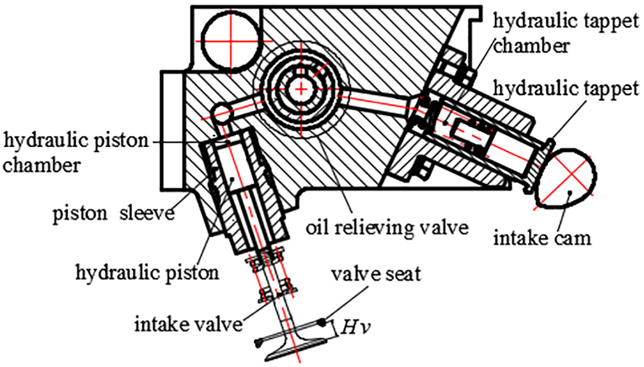
Sketch of the intake valve driving mechanism.
The structure and working principle of oil relieving valve
Oil relieving valve is composed of a couple of the valve spool and the valve sleeve. The three-dimensional structure of the oil relieving valve is shown in Figure 2. There is a center hole and a radial hole B which connect with the low-pressure system in the valve spool. There is a radial hole A and a circular groove which connect permanently with the high-pressure system in the valve sleeve. One oil relieving valve can control two cylinders.

Three-dimensional structure of the oil relieving valve.
Working principle of the oil relieving valve is as follows: the valve spool rotates synchronously with the cam. If the hole B and the hole A are not connected, the oil relieving valve is at the closing state, and the intake valve rises as the intake cam rotates. If the hole B turns to the position where it connects with the hole A, the oil relieving valve is at the opening state to let high-pressure oil flow into the low-pressure system, and the intake valve goes down under the force of the intake valve spring. The intake valve lift and the intake valve opening duration can be changed along with the different position of the radial hole A. Oil relieving angle is the crank angle when the radial holes A and B connect.
Working principle of the throttling valve
In FHVVS, the throttling valve consists of a couple of a hydraulic piston and a hydraulic piston sleeve, as shown in Figure 3. Hydraulic oil in the hydraulic piston chamber flows out through throttle holes and the throttle groove in the hydraulic piston sleeve when the intake valve falls back. As the intake valve lift gradually decreases, the effective throttling area of the throttle hole reduces rapidly. When the intake valve drops to a certain lift (2 mm for FHVVS), hydraulic oil can only flow out through the throttle groove, but not throttle holes. The effective flow area of the throttle groove is gradually reduced along with decrease in the intake valve lifts. Thus, volume of the hydraulic oil that flows out of the hydraulic piston chamber reduces, so that the valve seating speed reduces to ensure the smooth intake valve seating.

Three-dimensional structure of the throttling valve.
Simulation and validation experiments of FHVVS
Theoretical basis of the simulation modeling
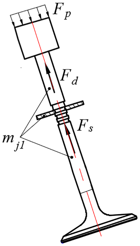
The system needs to be analyzed theoretically in order to establish the simulation model of FHVVS, describe the dynamic characteristics of the whole system, and determine the parameters of the simulation model. Hydraulic piston and the intake valve assembly are taken as the object, and force on the intake valve from gas in the cylinder is neglected. Figure 4 is the force analysis diagram of hydraulic piston and the intake valve assembly. As can be seen from Figure 4, hydraulic pressure from hydraulic piston chamber
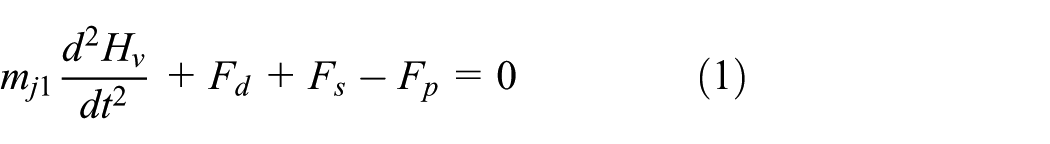
where
Force analysis diagram of hydraulic piston and the intake valve assembly.
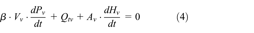
Based on the continuity equation of fluid, the differential equation of the pressure of the hydraulic tappet chamber
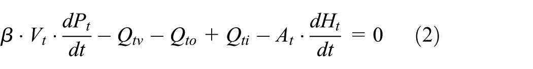
where

where
In the same way, according to the continuity equation of the fluid, differential equation of pressure
where
Ordinary differential equations of variables
The simulation model of FHVVS is shown in Figure 5. The simulation model consists of four parts: cam driving subsystem, hydraulic transmission subsystem, intake valve assembly subsystem, and controlling subsystem. Signals from cam driving subsystem are input into controlling subsystem to make hydraulic subsystem open the intake valve. The step of the simulation is set to be 0.01 ms. The model only discusses two intake valves in one cylinder because the high-pressure oil generated by a hydraulic tappet in the FHVVS can drive two intake valves and the movement state of each intake valve is independent.

Diagram of FHVVS model.
Introduction of the validation experiment
The SI engine BJ486EQ with dual overhead camshafts is selected to be the experimental prototype, each cylinder of which has four valves and rated power is 95 kW and rated speed is 5000 r/min. Main parameters of experimental prototype are shown in Table 1. FHVVS is mounted on the cylinder head of the prototype which is shown in Figure 6. In order to maintain versatility of the cylinder head of the original engine, both the intake and exhaust cams are combined on the exhaust camshaft. Each intake cam controls two intake valves of the corresponding cylinder through hydraulic pressure. The intake cam and exhaust cams of the first cylinder are marked in Figure 6. The oil relieving valve is, respectively, installed in the front case and the rear case. A synchronous gear is arranged in the middle of the camshaft, and the valve spool of the oil relieving valve is driven by the gear driving unit to synchronously rotate with the camshaft. A stepping motor that is mounted on the cylinder head cover drives the motor shaft in order to make the gear sector and the valve sleeve gear shown in Figure 2 mesh to adjust the oil relieving angle of the oil relieving valve. As can be seen from Figure 6, FHVVS is less than the size of the original cylinder head in the direction of the width and the length, which uttermost maintains compactness and the overall structure of the cylinder head.
Main parameters of the original engine BJ486EQV4.


Installation of FHVVS on the cylinder head.
Lifts of the intake valve and pressure of the high-pressure system are measured in the motored test bench which mainly comprises an engine cylinder head, a frequency transducer, a motor and measuring equipment, and a hydraulic pump station. The schematic diagram of the test bench is shown in Figure 7.

Interconnection between the test rigs for FHVVS.
The camshaft of the valve train is driven by the electric motor through transmission. The speed of the motor that is the half of engine speed is controlled by a frequency converter which can continuously adjust the speed of the electric motor within 0–3000 r/min. The hydraulic oil with suitable temperature and pressure in the FHVVS is provided by the hydraulic pump station that replaces the lubrication system of the original SI engine to ensure the cycle operation of the system, and it also provides lubricant oil for the camshaft and other moving parts in the experiment.
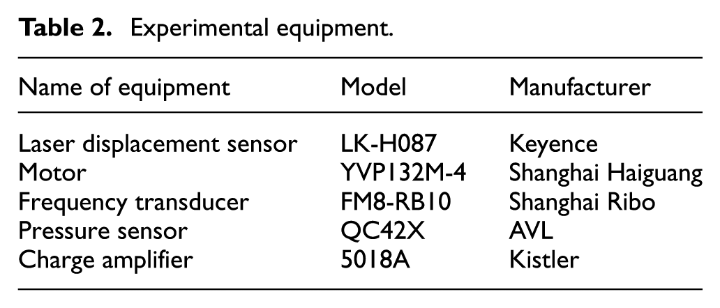
Intake valve lift signals, high-pressure signals, CDM (crank angle degree marker) signals, and TDC (top dead center) signals were collected in the experiment. The original signals were transmitted to a computer through high-speed data acquisition board in real time. Data were collected and processed by the computer. The main instruments are shown in Table 2.
Experimental equipment.
Results and discussion
Validation of simulation results and experimental results
For the validation of the simulation model, lifts with different oil relieving angles are achieved through the simulation and experiments on the motored test bench when the engine speed is 3000 r/min, which are shown in Figure 8. As can be seen from Figure 8, lift curves of simulation and experiment have the consistent trend and nearly the same shape. The maximum intake valve lift and the intake valve opening duration increase along with the increase in the oil relieving angle when the intake valve lift is less than the maximum designed lift at the same speed. The intake valve opening duration will continue to increase, while the maximum intake valve lift remains unchanged with the increase in the oil relieving angle when the intake valve lift reaches the maximum designed value. In conclusion, FHVVS can achieve continuously variable maximum intake valve lift and fully variable intake valve opening duration at a variety of speeds by adjusting the oil relieving angle.

Experimental and simulating intake valve lifts at 3000 r/min.
Intake valve lift and pressure of the hydraulic tappet chamber are shown in Figure 9 when the engine speed is 3000 r/min and the oil relieving angle is 100°CA ATDC. As can be seen from Figure 9, the simulation and experimental results of the hydraulic tappet chamber’s pressure and intake valve lift have basically consistent wave period and amplitude. The pressure of the hydraulic tappet chamber fluctuates periodically and the intake valve lift mainly depends on the intake cam profile when the crank angle is below the oil relieving angle. Hydraulic tappet chamber’s pressure decreases rapidly and the intake valve seats quickly after the lift under the function of inertia force when the crank angle is over the oil relieving angle.

Pressure of tappet chamber and intake valve lift at 3000 r/min.
Analysis of pressure fluctuation
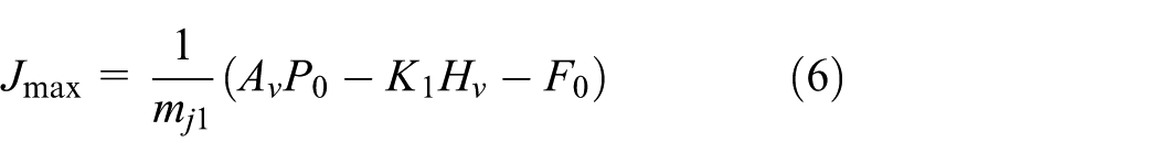
In order to further analyze the dynamic characteristics of the intake valve of FHVVS, with the damping force neglected, equation of the acceleration of the intake valve

where
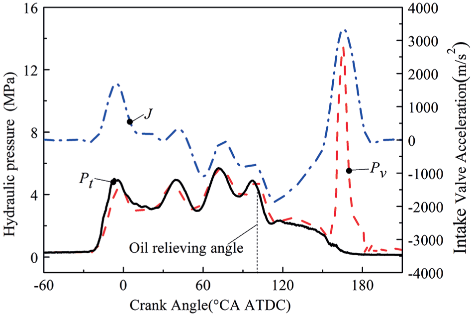
Experimental and simulating pressure fluctuation and acceleration of the intake valve.
As can be seen from Figure 10, when the crank angle is less than the oil relieving angle 100°CA ATDC, pressure of the hydraulic tappet chamber
Figure 10 indicates that periods of the intake valve acceleration
Pressure of the hydraulic tappet chamber at different speeds is shown in Figure 11 when the oil relieving angle is 125°CA ATDC. As can be seen from Figure 11, the pressure fluctuation in the high-pressure system is stronger and the peak increases, while the trough decreases as speed increases. The lowest pressure A occurs in the first trough when the engine speed is 5000 r/min. Obviously, as the speed increases, the value of the lowest pressure decreases further and is even below the pressure of the low-pressure system
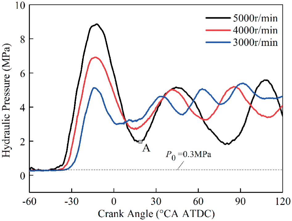
Pressure fluctuation of hydraulic tappet chamber at different engine speeds.
Optimization of the intake cam profile
Cam is the power source of intake valve movement and also the vibration source in FHVVS. Therefore, it is the fundamental problem to design a reasonable intake cam profile to decrease the pressure fluctuation in the hydraulic system. Thus, the optimum cam profile is selected from many different cam profile schemes by simulation to prevent the phenomenon of “lift distortion” to occur at high speed. Figure 12 shows the theoretical intake valve lift and acceleration determined by intake cam profile of FHVVS and prototype. It can be seen that compared with the prototype, the theoretical intake lift and acceleration determined by the intake cam profile of FHVVS have the following characteristics:
The maximum theoretical intake valve acceleration of FHVVS is set at the beginning of the working section, and its value is reduced properly.
The AB segment in the curve of FHVVS that is between the positive intake valve acceleration and the negative intake valve acceleration becomes very flat.

Lift and acceleration of intake valve on theory.
Experiments on FHVVS under the high speed are carried out in order to analyze the dynamic performance. Figures 13 and 14, respectively, show lift and acceleration of the intake valve when the oil relieving angle is 43°, 123°CA ATDC at the speed of 5000 r/min. As can be seen from figures, lift curves of FHVVS are smooth and the intake valve seating is soft, which illustrates the steady performance of FHVVS at the rated speed of 5000 r/min.

Intake valve lifts at 5000 r/min with different oil relieving angles.

Intake valve accelerations at 5000 r/min with different oil relieving angles.
In Figure 14, the maximum negative acceleration
The phenomenon of “lift distortion” occurs if the pressure of the high-pressure system is lower than that of the low-pressure system
Optimization of the throttling valve
In the seating stage of the intake valve, flow of hydraulic oil through the throttling valve is supposed to be controlled to adjust the valve seating speed and buffer impact of intake valve seating. An optimal structure of the throttling valve is obtained through the simulation to ensure the smooth seating of the intake valve.
Two different schemes of throttling valves are shown in Figure 15(a). Throttling area reduces rapidly as the intake valve lift decreases.

Effects of different schemes of the throttling valve on intake valve seating process: (a) throttling area of different throttling valves and (b) intake valve lifts and speeds.
The intake valve lift and speed obtained from experiments are shown in Figure 16 when the engine speed is 5000 r/min and the oil relieving angle is 55°CA ATDC. The valve seating speed is 0.21 m/s for FHVVS, and there is no significant rebound phenomenon. The intake valve seats softly.
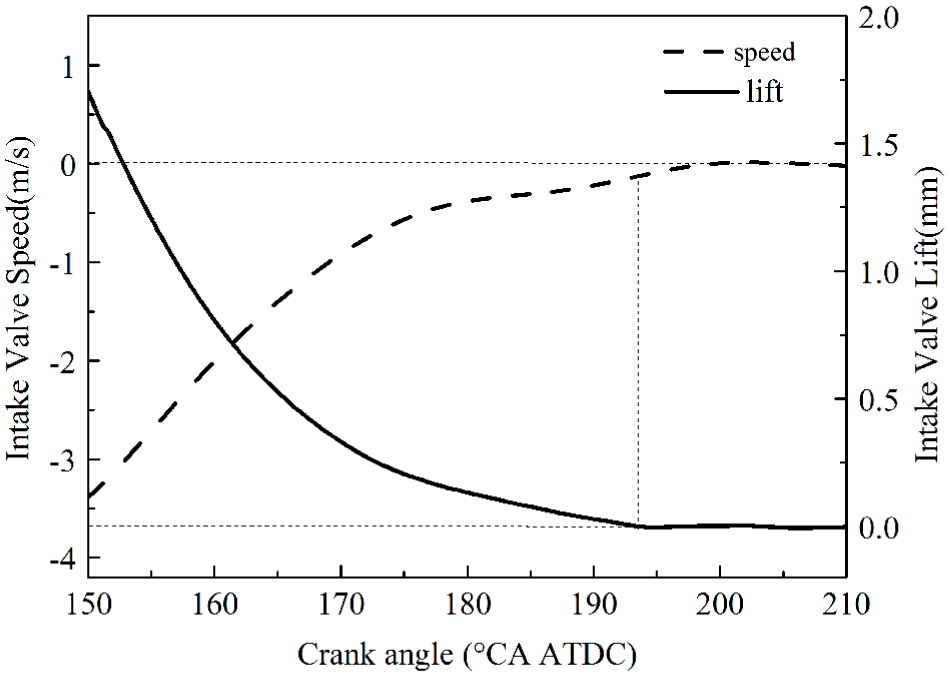
Experimental intake valve lift and speed at intake valve seating stage at 5000 r/min.
Conclusion
One new FVVT called FHVVS has been introduced in this study. Simulation and experiments have been performed in this article to study pressure fluctuation and high-speed dynamic characteristics of FHVVS. Some conclusions are listed as follows:
FHVVS is innovative to use oil relieving valve as an oil control switch. Simulation model and experiments have proved that FHVVS can achieve fully variable valve lift and duration.
With the increase in the engine speed, the pressure fluctuation in FHVVS becomes stronger. Once pressure in the high-pressure system is lower than that of the low-pressure system
The intake cam profile of FHVVS is optimized by simulation and experiments which show that it is more appropriate for FHVVS that the intake cam profile has smooth acceleration curve and its maximum intake valve acceleration point on theory is set at the initial stage. The optimized cam profile makes intake valve movements stable at the speed of 5000 r/min, and there is no lift distortion.
The valve seating speed of FHVVS is controlled by a throttling valve the structure of which is optimized through simulation and experiment. Proper minimum throttling area
Footnotes
Handling Editor: Jose Antonio Tenreiro Machado
Declaration of conflicting interests
The author(s) declared no potential conflicts of interest with respect to the research, authorship, and/or publication of this article.
Funding
The author(s) disclosed receipt of the following financial support for the research, authorship, and/or publication of this article: This work was supported by National Natural Science Foundation of China (51375265) and the National Key Basic Research Plan (2013CB228404).