
Abstract
According to the on-orbit servicing requirements of spacecraft, this article presents a new type of space-climbing robot that can climb onto the target spacecraft for repairing, rescuing, and removing orbital debris. This robot mobile system is composed of a piezoelectric actuation leg, microadhesive feet, and others. In the environment of zero gravity, the space-climbing robot can cross obstacles through crawling movement and turnover movement. The gripping force of the robot is supplied by the adhesive capacity of the robot feet. The research on its adhesion mechanism is the basis of the robot feet design and motion control. The design of a robot feet microarray structure imitates the adhesion mechanism of gecko seta. Based on the theory of interface micromechanics, we used EDEM software to establish the simulation model of vertical microarrays. This work will simulate the microarray’s attaching and detaching processes with different modes of motion, analyzing each microarray’s adhesive property. In order to make the structure of microarray has ideal adhesive property, microarray parameters including length–diameter ratio and arrangement density of microarray are optimized. By EDEM-ADAMS coupling simulation, the robot can attach to the surface of the spacecraft and verify the adhesion function of the space-climbing robot.
Introduction
Space-climbing robot achieved a new spatial load control method.1–4 The robots climb on the target spacecraft surface and stick to it in order to achieve high flexibility and accessibility with low risk. The robot is suitable for non-cooperative space target on orbit control missions due to the advantages of low cost, small volume, and lightweight while facilitating the main spacecraft to perform multiple tasks. Research on the space-climbing robot will provide powerful support and guarantees for space activities, which has important research value and practical meaning.
The technology of space-climbing robots includes movement and adsorption. The adsorption technologies of traditional climbing robots are unable to contact the surface in space environment.5–7 In the process of biological evolution, geckos are able to move on walls and ceilings agilely, such ability has always been an object for researchers to focus on. The study found that the viscosity between the gecko toes and the contact surface is driven by the Van der Waals force. The majority of gecko studies investigate gecko adhesion and stripping mechanism in many counties. Autumn (United States citizen) and his team measured single adhesion of setae on a gecko foot, and the results demonstrated that the setae stick firmly to the surfaces because of van der Waals forces between the setae structures and the surface.8,9
Under a microscope, it was observed that the bottom of Gecko foot is covered with millions of fine hairs.10–12 The end of every hair is divided into approximately 400 to 1000 branches. The research shows how the gecko foot turns stickiness on and off instantly on a glass ceiling. 13 When a Gecko attached to a smooth surface, setae are toward the foot orientation and drawing back. Flexible foot disks stretching outwards make the hair attach to the greatest extent on the surface and increase the adhesion force. When it rests, the setae are curved inward toward the center of the foot. When the setae are straightened, this force disappears, and they unstick seamlessly.
Based on the deep understanding of the dry adhesion microstructure of gecko, the microarray structure is realized by microelectromechanical systems (MEMS) technology.14–19 Carbon nanotube adhesion microarrays with high length–diameter (L/D) ratio by chemical vapor deposition method are prepared.20–23 Based on this adhesive material and adhesive structure, many countries in the world have carried out the development of wall-climbing robot and have made some research achievement.
In 2006, Carnegie Mellon University has developed Geckobot. 24 This robot uses a diagonal gait in the forward movement, and the steering engine at the leg and trunk connection provides its power. The maximum climbing angle is 90°. Stanford University in the United States had contributed to the field of bionic climbing robots. In 2006, Stanford University Professor M. Cutkosky’s research team invented a new four-feet wall-climbing robot Stickybot. 25 This robot uses a directional adhesive array material to achieve adhesion, and its maximum climbing speed is 24 cm/s. In 2011, Simon Fraser University invented an improved version of the spider robot Abigaille-II. 26 The ground travel speed is 4.5 cm/s and the moving speed on the vertical wall is 0.1 cm/s.
The traditional wall-climbing robot is aimed at the global environment. Space-climbing robot is used in space environment. Therefore, based on the traditional wall-climbing robot, the space environment factor needs to be considered. Such as low-gravity environment, high- and low-temperature environment, and high-vacuum environment. The climbing robot’s motion gait and attachment method are designed based on the space environment.
The future space facilities will be greater than today’s satellite and space stations, will be more complex, will be more difficult to achieve, and will require a high degree of autonomy of other robots to cooperate with the large space robotic arm assembly, inspection, and maintenance of these facilities. In order to achieve the flexibility, mobility, and easy to carry, workspace volume of the climbing robot has a strict requirement, so the micro small climbing robot research of climbing robot design space has an important guiding significance.
Structural design of space-climbing robot
Robot mechanism configurations
Combined with the unknown surface morphology characteristics of a non-cooperative target spacecraft. The climbing robot uses rotation joint, which has a stronger obstacle climbing ability that helps robot cross a concave–convex surface. Traditional multi-legged robots on the earth can spin a maximum height related to their structural size, while in the space environment where there is no gravity, there is no difference between the robot’s top and bottom. Robots can levitate in space and climb obstacles by inverting themselves. The obstacle that robot can climb is not affected by the robot’s structural size. The only thing that needs to be considered is the relationship between the robotic leg size and the shape of concave–convex surface. Analysis of gecko anatomy and movement rules found that a gecko’s four feet were symmetrically distributed. Removing the gecko feet, each leg has three joints and 5 degrees of freedom. These are the hip joint between the body and the thighbone, the knee joint between the thighbone and the shank, and the ankle joint between the shank and the foot.
Through the analysis of the gecko’s body structure and motion laws, the robot mechanism is shown in Figure 1. It has 5 degrees of freedom with a 2-1-2 distributions. The robot’s body connecting part has 2 degrees of freedom. The knee joint and the ankle joints have 1 and 2 degrees of freedom, respectively. The robot body length, width, and height were 180 mm × 100 mm × 70 mm. The closest leg to the body of the robot’s leg structure is named rod 1 and so on. Limiting motor drive torque and robot movement requirements, the length of connecting rod 1 is 23 mm with yaw and pitch joints perpendicular to each other. The length of connecting rod 2 is 43 mm. The length of connecting rod 3 is 82 mm. The contact area of the foot is 18 mm × 12 mm. With the hip pitch joint and knee pitch movement, the overall size of the robot can be controlled within 200 mm × 200 mm × 100 mm. Due to the smaller body size, in order to ensure the strength of the robot, the aluminum alloy is used as the material of the robot rod. The robot designed in this article can be crawled on smooth surface. For rugged surfaces, the flexible design of the robot foot can be enhanced to improve the robot’s adaptability. There is an ejector on the back of the robot that can remove orbital debris when the connection is established between the space robot and the target spacecraft. The forepart has two manipulators. They can be used for diagnosis and maintenance, and this mechanism has the following advantages after meeting the above requirements:
A variety of plane motion, beneficial to achieve complex tasks;
Symmetrical structure, with the ability to complete tasks in any state.
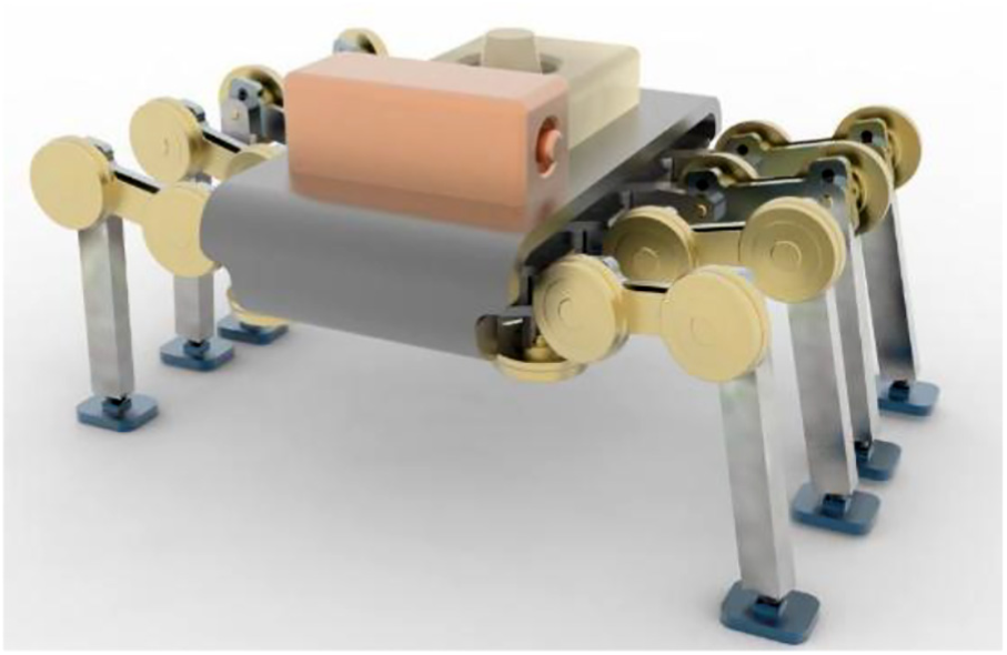
Robot mechanism.
Robot studies on motor function
After selecting the form of the joint, analysis of the space-climbing robot’s motor function was tested in order to test whether the robot can satisfy the expected moving function.
Crawling movement
While four of the robot’s legs attached to the contact surface, the other four legs detached from the contact surface, and through the legs movement and the joint rotational movement, the robot moves forward. Until the four detached feet contact the surface again, the robot completes one crawling movement. Through the crawling movement, the robot can move forward. As shown in Figure 2, the climbing robot can achieve the function of moving forward by crawling movement.

Crawling movement: (a) initial position, (b) revolute joints, (c) leg movement, (d) revolute joints, (e) leg movement, and (f) across the surface.
Turnover movement
First, the space-climbing robot’s four feet on the one side parallel adhere to the contact surface. The four feet on the other side detach from the contact surface. Then, space-climbing robot can turn over to the side which has adhered to the contact surface. Until the four detached feet contact the surface again, the robot completes one turnover movement. Then, the previous action is repeated to cross the obstacle. As shown in Figure 3, through the turnover movement, the obstacle that the robot can climb is not affected by the robot’s structural size. The only thing that is taken into account is the relationship between robotic leg size and the shape of concave–convex surface.
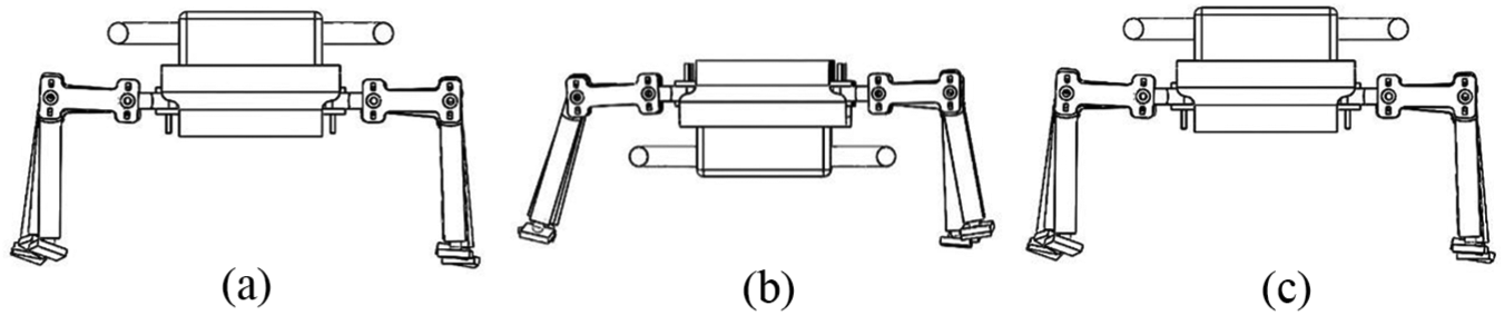
Turnover movement: (a) initial position, (b) revolute joints and turnover movement, and (c) across the surface.
Adhesion theory model analysis based on discrete element
The feet of space-climbing robot play a key role in the realization of the movement process. The gait of the robot is realized by adhering foot alternation. The feet adhered with the contact surface, and the individual joints drive its mechanism. In the space environment, the adhesion properties between the contact surface and the robot feet have a direct impact on the robot’s reliable adhesion and motion state. In order to achieve fast detaching and reliable attaching properties between the contact surface and the robot feet, feet design used a bionic setae structure. As shown in Figure 10, the adhesion feet structural configuration is designed by a discrete element method. The foot of the robot is created by a vertical microarray and silicone material with high temperature and radiation-resistant properties. Its low stiffness helps to improve the adhesion between the microarray and the contact surface. So, microarray material used is silicone material and molding process was used to fabricate microarray.
We use microscopic Hertz contact theory analysis to analyze the setae attaching and detaching process in detail. Due to the existence of the intermolecular interaction force, to increase the surface area of the material system, the outside world is bound to provide energy for this material. The energy required to increase a unit area of matter is the surface energy. So, the greater the surface area, the greater the surface energy. At the microscopic scale, microarray structures have a large surface area ratio. The microstructure has high specific surface area in that the surface energy cannot be ignored and can even consider dominant. This surface effect is caused by the scale effect.
There are many contact models for Van der Waals forces. In the microstructure, the bonding of multiple clusters of particles forms the microarray structure. Therefore, this article uses the discrete element method to model the microarray structure. In EDEM software, the way of particle bonding is modeled. The Johnson, Kendall, and Roberts (JKR) model is based on the direct contact model of two spherical particles and considers the effect of the deformation of the two spheres on adhesion during adhesion. Therefore, the JKR theoretical model is selected in the adhesion model between microarray and spacecraft.
The JKR theory is a microscale classical contact theory. The JKR theory is explained for two spheres of radii R1 and R2 pressed together under a load P. The elasticity moduli of two spheres are E1 and E2. The Poisson ratio of two spheres is v1 and v2, as shown in Figure 4.

Schematic view of two spheres pressed together.
The contact problem of two elastic spheres is equivalent to the contact problem between a rigid sphere with radius R and an infinite sphere with elastic modulus of E. The formula for R and E is

Under the JKR theory model, the calculating formula of normal stress distribution in the contact zone is

The formula for δ is

The formula divides into two parts: the first part is the stress of Hertz and the second part is the stretching stress by surface energy. The relational expression of the external load on the spheres is P and the contact radius a is

R is the equivalent radius, E is the equivalent elastic modulus, and w is the work of adhesion per unit area. The deformation of the spheres is by the external load on the spheres and the adhesion force on the partial contact. When there is no external load on the spheres and an increase of tensile load, the contact radius becomes increasingly smaller. When “a” reaches to a minimum value, the stripping force reaches to a maximum value

The minimum value of the contact radius is as follows

Based on the above theoretical model, use the discrete element simulation software EDEM. The JKR model is used to build a discrete element model to simulate the process with single seta and the surface of the spacecraft, as shown in Figure 5. The Hertz–Mindlin with bonding contact model is adopted as the simulation model of the adhesion array. This model can be used to bond particles, which are bonded using a finite size “adhesive.” This bond can withstand both tangential and normal displacements until the maximum normal and tangential shear stresses are reached, namely, the bond break point.

Microscopic diagram of robot foot and the surface of spacecraft.
Microarrays are constructed of multiple particles bonded together. The parameters in the discrete element software need to be set based on the material properties of the microarray and the material properties of the spacecraft surface. The characteristics of the model obtained by discrete element modeling are consistent with the theoretical model. The simulation parameters are determined, and the interaction parameters of the robot foot and the surface of the spacecraft are determined by parameter matching. Next, the process of the robot foot adhesion on the surface of the spacecraft is simulated. Then, the effect of the adhesion performance with robot foot microstructure is analyzed.
By formula (5), the adhesive force of a single sphere is in direct proportion to the radius of the sphere. When the total contact area is fixed, the total adhesive force will increase with the decrease in each sphere’s radius. This is because the contact radius of each particle with the surface in contact is different. When the size of the particles and the adhesion work is determined, the adhesive force of each particle with a contact surface is shown in formula (7)

The adhesive force of each single fiber with a contact surface is shown in formula (8)
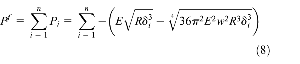
where n is the total number of particles involved in contacting spacecraft surface on a single fiber. The number of particles involved in the contact determines the adhesive force of a single fiber.
The number of fibers involved in the contact determines the adhesive force of a microarray. F as the total adhesive force of microarray with contact surface is shown in formula (9)

while m is the total number of fibers involved in contacting spacecraft surface on a microarray, above is the discrete element model of the vertical microarray with horizontal terminal structure. According to this model, we can analyze the adhesive force between microarrays and the contact surface of spacecraft. Then, we can analyze the driving forces of the space-climbing robot. The simulation for the rest of this article is based on the above theoretical model.
Research on adhesion mechanism simulation
Simulation modeling and parameter optimization of microarray based on discrete element
The gecko uses multi-movement to achieve adhesion force between the foot and the contact surface. Following the gecko’s seta structure, a vertical microarray model was proposed and simulated by DEM. The size was designed in this model in accordance with the size of gecko’s setae structure. As a gecko’s seta has a length of approximately l = 120 µm, a cross-sectional diameter d = 4.2 µm. 27
The DEM (discrete element method) is a numerical simulation method to solve the multi-particle system modeling by tracking the relationship between particle motion and the interaction between particle and environment with time. Currently, there are mainly two kinds of discrete element simulation of computer software: particle flow code (PFC) and EDEM. Compared with PFC, EDEM has a better user interface, which supports SolidWorks, Pro/E, and other three-dimensional computer-aided design (CAD) software, so the construction of complex geometry is more convenient. In addition, it has a good parallel computing efficiency and speed of solution, and particle computing can reach millions of magnitude. In this article, EDEM software will be used to model and simulate vertical microarrays. From the discrete element analysis, the vertical microarray of a single fiber can be seen as a cylinder composed of multiple particles. The adhesive structure on the robot foot was modeled by EDEM software. The simulation of the adhesion and desorption process of the robot feet was carried out. A simplified microarray discrete element model is shown in Figure 6. The base of the microarray consists of large particles, and the ends of the microarray are composed of multiple tiny particles. Through the bonding model, the tiny particles at the end of the microarray structure were bonded to the large particles in the substrate to complete the modeling. The simplification of the microarray structure was completed. The adhesive force is mainly the result of van der Waals forces between the end of the microarray adhesion structure and the contact surface. The particle size of the structure is refined at its end portion and the radius was set to 0.8 μm. The particle radius of the microarray substrate has no effect on the simulation. The JKR contact model is used as the adhesive elastic contact model to analyze the adhesion properties of microarray structures. Adhesion forces between the particles from the end portion of the fiber and the contact surface are based on the JKR model.
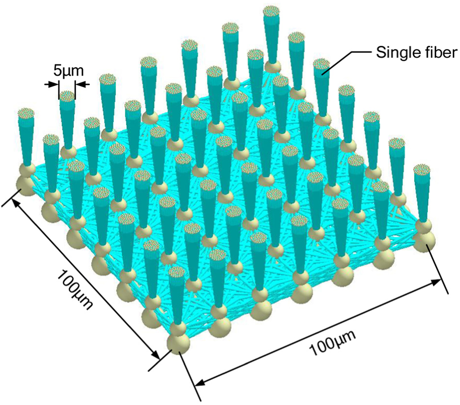
Discrete element model of vertical microarray with horizontal terminal structure.
Based on the above parameters, the microarrays’ attachment condition was simulated and analyzed. Furthermore, when preloading and stretching the microarray, microarrays get detached from the surface, so that the detaching of the vertical microarrays can be simulated and the adhesive properties can be analyzed. Figure 7 shows the vertical microarrays’ detaching process in the vertical direction, which has no horizontal movement.
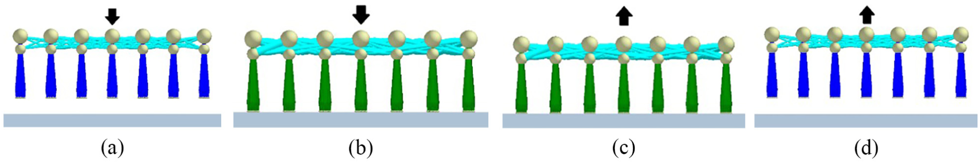
Vertical microarrays’ detaching process in vertical direction: (a) initial position, (b) prepressing, (c) normal stretching, and (d) detaching.
By changing the aspect L/D ratio and the density of the array, further modeling and simulation of the microarray were carried out, and the optimization parameters of the microarray structure were determined by the analysis of the adhesion characteristics. This research can provide theoretical help for the study of the adhesion mechanism and the mode of adhesion of the climbing robot foot.
Based on the above theory, the following parameters are proposed: 0.1 mm×0.1 mm vertical microarrays with 2:1, 3:1, 4:1, and 6:1 L/D ratios and 4 × 4, 5 × 5, 6 × 6, and 7 × 7 microarray densities. The value of each fiber’s diameter is 5 µm and the value is fixed. Every vertical microarray’s attaching process is simulated by discrete element software and analyzed by the adhesion property under different parameters. The influence of L/D ratio and microarrays’ density on normal adhesive force was analyzed. Figures 8–11 show microarrays’ EDEM simulation model in different parameters.

Microarrays’ EDEM simulation model with L/D ratio of 6:1: (a) 7 × 7, (b) 6 × 6, (c) 5 × 5, and (d) 4 × 4.
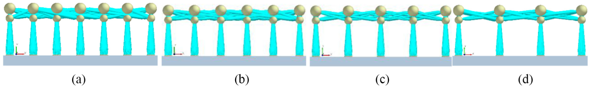
Microarrays’ EDEM simulation model with L/D ratio of 4:1: (a) 7 × 7, (b) 6 × 6, (c) 5 × 5, and (d) 4 × 4.

Microarrays’ EDEM simulation model with L/D ratio of 3:1: (a) 7 × 7, (b) 6 × 6, (c) 5 × 5, and (d) 4 × 4.

Microarrays’ EDEM simulation model with L/D ratio of 2:1: (a) 7 × 7, (b) 6 × 6, (c) 5 × 5, and (d) 4 × 4.
When the vertical microarray get detached from the contact surface, it is possible to obtain the adhesion force of the contact surface at each moment. The simulation shows the maximum adhesion force under different parameters with four kinds of microarray density and four kinds of L/D ratio. The curve in which the normal adhesion force of contact surface changes with time under different parameters of vertical microarrays is shown in Figure 12.
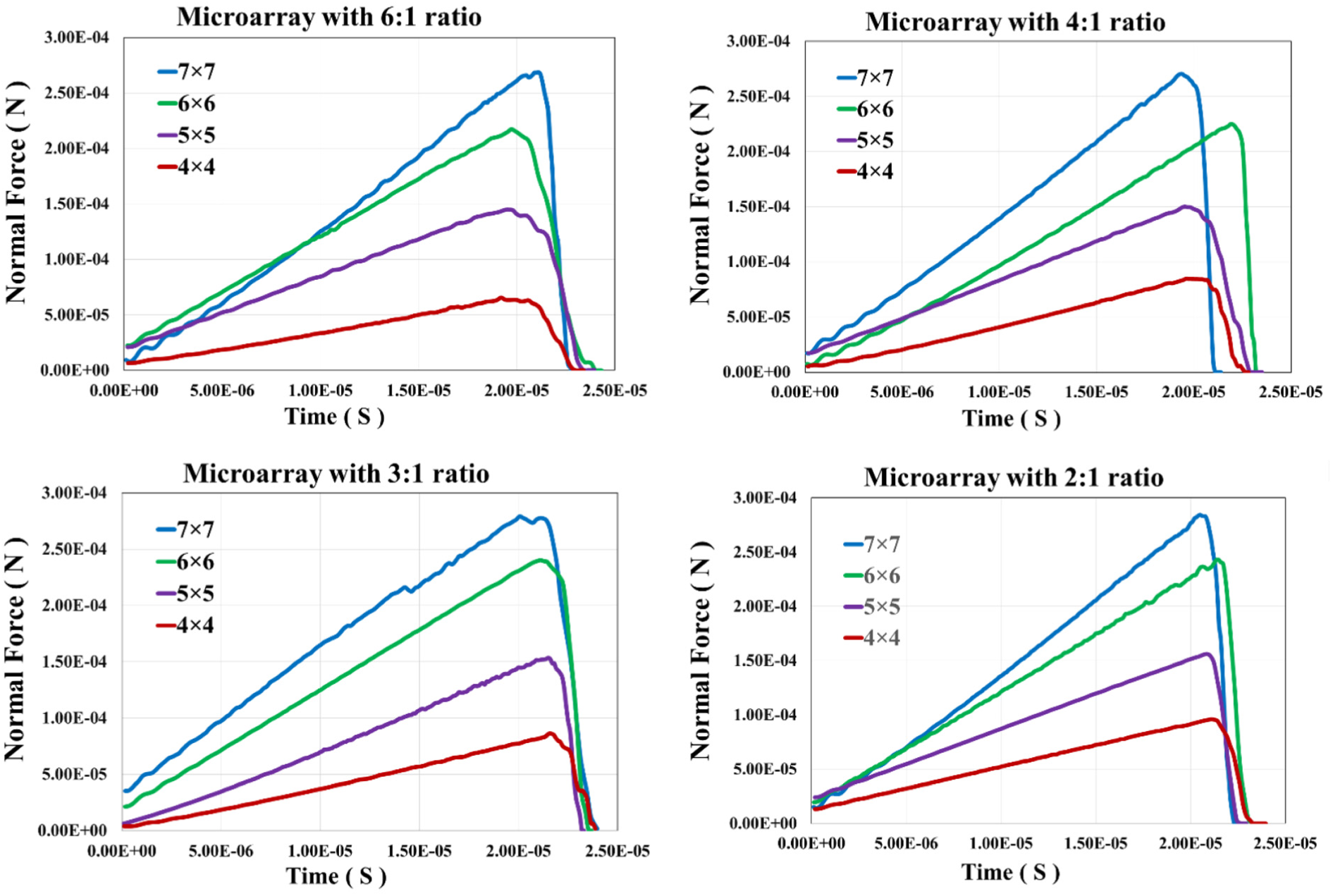
Microarrays’ normal force curve with (a) 6:1 ratio, (b) 4:1 ratio, (c) 3:1 ratio, and (d) 2:1 ratio.
The maximum adhesion force of microarray under each parameter is summarized, and the data are shown in Table 1. The curve of microarrays’ maximum force with different parameters is shown in Figure 13.
Maximum normal adhesive force in a variety of microarray parameters.

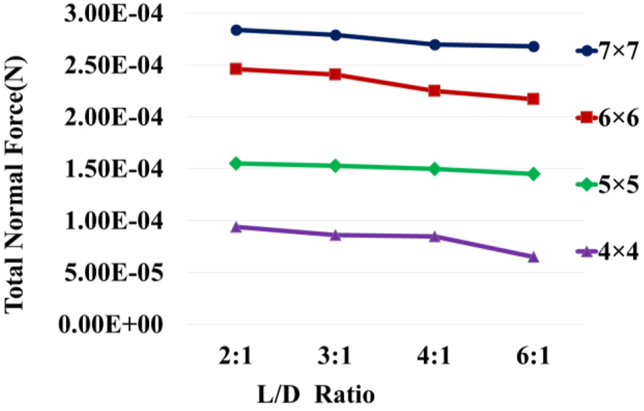
The curve of microarrays’ maximum force with different parameters.
As can be seen from the curve, with the growth of microarray length, microarrays’ normal adhesive force decreases. When the length of the microarray is short, the deformation of microarrays is small. The majority of the particles are involved in the adhesive effect during the detaching process which makes the adhesive force of the microarray become larger. But the contact surface in the simulation is smooth and the contact surface in the real world is rough. When the microarrays’ length is too short, microarrays are not completely in contact with rough surfaces. The adhesive ability of microarray to adapt to the rough surface is weakened. Therefore, the L/D ratio of 3:1 was selected to be the optimal parameter.
The simulation result shows that the adhesive force of a single fiber is F = 9.4 × 10⁻⁶ N. In Table 2, the microarrays’ adhesion efficiency η is concluded by solving the ratio between microarrays’ adhesion force and the theoretical maximum force. The microarrays’ adhesion efficiency can reflect the role of each fiber involved in the adhesion process. The analyses of the adhesion efficiency provide a comprehensive comparison of different parameters with microarray adhesion characteristics.
Microarrays’ adhesion efficiency with different parameters.

With the increase in microarray density, the adhesion efficiency increases at first and reaches the maximum at the density of 6×6 and then decreases. According to the theoretical analysis, single-contact surfaces can improve adhesive strength by dividing into a plurality of smaller contact surfaces. Gecko’s foot has great adhesive force, and due to the high density of the seta array, it makes the foot contact with the surface by many contact points. Therefore, greater adhesive force can be achieved by increasing the density of the microarray. With the increase in microarray density, the probability of bonding between fibers is greatly increased. Therefore, bonding between large numbers of fibers is equivalent to reducing the number of fibers, resulting in a reduced adhesion property of the microarray to detach from the contact surface. The microarray processing difficulty and processing costs are greatly increased. Therefore, choose the microarray density of 6 × 6 to be the optimal parameter.
Simulation on optimization of microarray detaching angle
Microarray structure can improve the robot foot’s adhesion force. The robot needs alternating attaching and detaching movement in the process of moving. Therefore, the robot’s feet need to achieve the easy detaching in the process of leg lifting. After determining the optimal microarray density and L/D ratio, in order to reduce the maximum adhesive force in the detaching process, it is necessary to analyze the optimal detaching angle of the microarray. Choose the microarray with density of 6 × 6 and L/D ratio of 3:1. The simulation process is achieved by first preloading the microarray to the surface and then detaching the microarray until the microarray is away from the surface. In order to determine the optimal detaching angle, we simulated and analyzed microarrays in different detaching angles. The whole detaching process is shown in Figure 14.

Microarrays’ detaching process: (a) initial position, (b) prepressing, (c) tangential stretching, and (d) detaching.
When the vertical microarray is detached from the contact surface in both horizontal and vertical directions, it is possible to obtain both normal adhesive force and tangential adhesive force of the contact surface at each moment. Through multiple sets of simulation, the maximum normal adhesive force and the maximum tangential adhesive force in different detaching angles are shown in Table 3. Figure 15 shows the maximum adhesive force curve of the vertical microarray with horizontal terminal structure in different detaching angle. Based on the normal force and tangential force, the size of the resultant force can be obtained.
Maximum normal adhesive forces and the maximum tangential adhesive forces in different detaching angles.


Maximum adhesive force curve of the vertical microarray in different detaching angle.
Based on the data in Table 3 and Figure 15, the relationship between the adhesive force and the detaching angle can be summarized. The results are as follows: with an increase in the detaching angle, the tangential adhesive force decreases and the normal adhesive force increases. With 0° detaching angle, the maximum tangential adhesive force on the vertical microarrays Ft = 2.34 × 10⁻⁴ N. With 90° detaching angle, the maximum normal adhesive force on the vertical microarrays Fn = 2.22 × 10⁻⁴ N. The rate of change of the tangential adhesive force and the normal adhesive force decreases with the increase in the detaching angle. Thus, when the detaching angle is between 0° and 20°, the tangential adhesive force of the vertical microarray is large, and the normal adhesive force of the vertical microarray is small. When the detaching angle is between 20° and 25°, the resultant adhesive force of the vertical microarray is a minimum, Fr = 1.23 × 10⁻⁴ N. When the detaching angle is between 25° and 90°, the tangential adhesive force of the vertical microarray becomes small and the normal adhesive force of the vertical microarray becomes large. The normal maximum adhesive force is Fn = 2.22 × 10⁻⁴ N.
Research on coupling simulation of climbing robot based on discrete element and dynamics
The establishment of the coupling simulation system
Import the 3D model of the climbing robot body into EDEM. EDEM is a discrete element simulation software. On this basis, the discrete element model of the climbing robot feet’s microarray is established. In order to improve the speed of operation, ensure that the total area of the microarray and the equivalent adhesive force are constant as a prerequisite. The fiber’s diameter and the distance between the fibers and the length of the fiber are proportionally magnified. Figure 16 shows a discrete element model of a climbing robot and a microarray structure of a single robot foot.

The discrete element model of a climbing robot.
Due to the movement, multiple geometries cannot be set in EDEM. Therefore, use ADAMS to establish the kinematic relation between the joints of the climbing robot. A climbing robot’s model established by ADAMS is shown in Figure 17. After establishing the kinematic pair of each joint of the robot, the kinematic gait of the robot is designed for the crawling mode. Robot first left side foot, third left side foot, second right side foot and fourth right side foot as a group the other feet as a group, alternately crawling forward. The horizontal distance between the robot’s hip joint and ankle joint is 66 mm. Due to the size of the robot, the crotch joint only allows 12° rotation at each step. So, the robot foot can move forward 11 mm each step.

The climbing robot model in ADAMS.
The motion gait of the climbing robot is designed based on the crawling movement. By analyzing the adhesion property of the microarray, it can be concluded that the optimal detaching angle of the robot foot during the detaching process is between 20° and 25°. Determine the length of the robot thigh and calf. At the initial position, the thigh is parallel to the contact surface and the calf is perpendicular to contact surface. When the climbing robot feet detach the contact surface by 20° detaching angle, the ratio of the calf rotation angular velocity to the thigh rotation angular velocity is 0.44. When the climbing robot feet detach the contact surface by 25° detaching angle, the ratio of the calf rotation angular velocity to the thigh rotation angular velocity is 0.24.
Movement gait of the climbing robot’s driving leg is set in the ADAMS. The adhesive foot is detached from the contact surface. Three translational and three rotational components for the robot foot are calculated by ADAMS and transferred for the required robot foot to EDEM each time step. Three force components and three torque components are calculated by EDEM and transferred to ADAMS each time step. ADAMS uses these data to calculate the robot foot translational and rotational components. Cyclic transfer data are used to complete the coupling calculation. MBD is the abbreviation of macroblock design. The flowchart is shown in Figure 18.
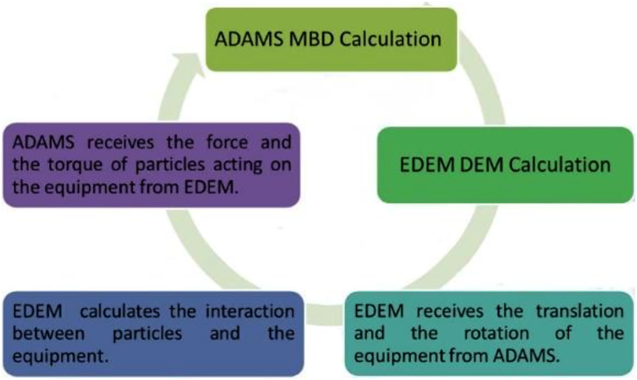
The flowchart of coupling simulation.
As shown in Figure 19, through the Part List, select the geometry involved in the coupling in ADAMS. Accurately enter the name of the geometry in the EDEM that matches the previous one and record the coupling relationship. Then in the Force column, the left side of the ADAMS interface, shows bidirectional coupling back to the geometry of the force from EDEM. Run the co-simulation model to complete the coupling simulation analysis of the robot crawling process.
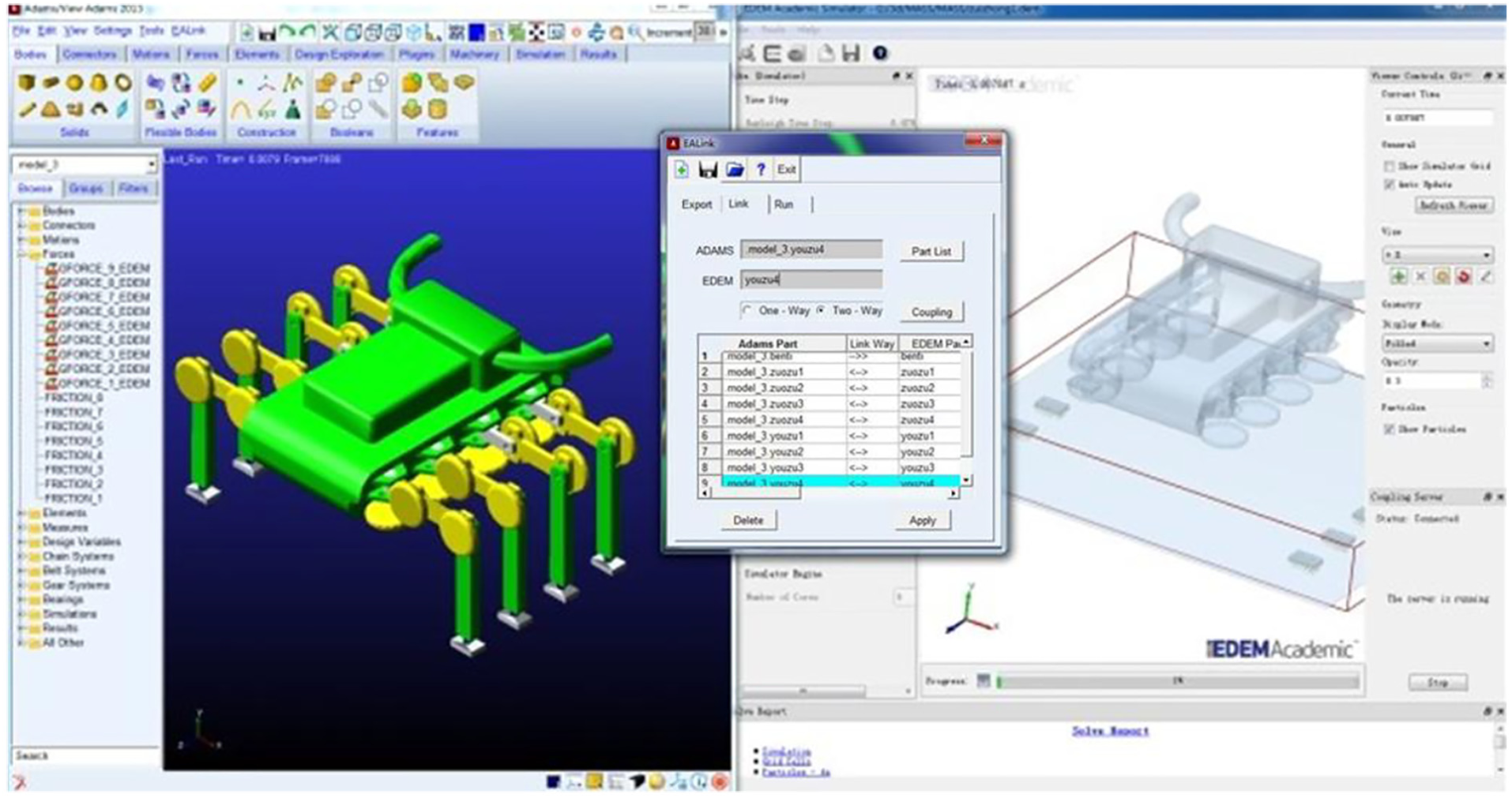
Established EDEM-ADAMS co-simulation platform.
Analysis of coupling simulation results
The gravity acceleration parameter is set as 0 m/s2. Calculate the coupling simulation model to complete the discrete element simulation of the climbing robot foot detaching and attaching process. Figure 20 shows the crawling movement process of the robot model in EDEM.
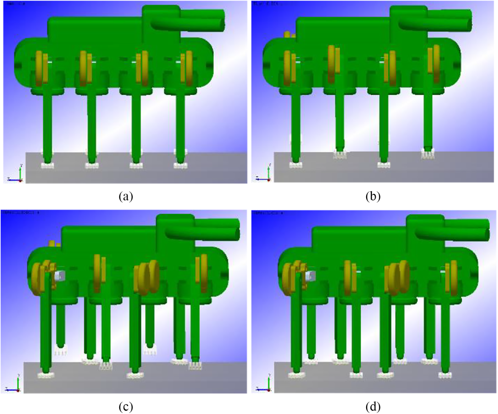
The crawling movement process of the robot model: (a) initial position, (b) lifting legs, (c) moving forward, and (d) settling down.
In the simulation process, the robot foot attaches to the contact surface firmly, and the robot can crawl on the contact surface with no slip or detachment in zero-gravity environmental conditions. In the robot crawling process, the curves of the normal and tangential adhesive force of the robot’s four feet on the contact surface are shown in Figure 21.

The curves of the normal and tangential adhesive force of the robot’s four feet which were attached on the contact surface.
As observed from the curve, when the robot has just begun to lift the leg, the spacecraft surface will have a greater stress force on the four feet in contact with the surface. When four legs are detached from the surface of the spacecraft completely, the four feet in contact with the surface of the spacecraft will have a large alternating force in the normal direction. In the course of the robot stepping forward, the four feet in contact with the spacecraft will provide a small tangential force to the climbing robot.
Base on the data in Table 4, It can be observed that in the process of the robot crawling forward, the fourth right foot suffers the maximum normal adhesive force, Fn = 0.608 N. The second right foot suffers the maximum tangential adhesive force, Ft = 0.104 N.
Maximum normal adhesive forces and the maximum tangential adhesive forces of each foot.

From the simulation data, it can be observed that in the robot crawling process, the robot foot’s adhesive force requirement on the normal direction is higher than the force on the tangential direction. This provides a direction for the subsequent study of the adhesion of microarrays. When lifting the legs, the contact surfaces still have a greater adhesion force on the robot foot that is connected to the lifting leg, which leads to the other four feet in contact with the surface to have a large alternating force in the normal direction. So, in the subsequent study, it is necessary to do further research on increasing the microarray’s normal adhesion force and the property of easy detaching.
Conclusion
This article presents a new type of space-climbing robot. The robot mobile system consists of a piezoelectric actuation leg and microadhesive feet and other components. Through the configuration analysis, the robot is composed of eight piezoelectric actuation legs. Each leg has three joints with 5 degrees of freedom. The robot’s crotch joint and ankle joint have 2 degrees of freedom with roll–pitch organization. In the environment of zero gravity, the space-climbing robot can cross obstacles on the target through crawling movement and turnover movement. The robot’s microscopic adhesion foot learns from the adhesion mechanism of gecko setae. Based on the structural design above, discrete element software was utilized to build a simulation model. The theoretical model is used for strong attachment and fast detaching ability analysis. This model was used to build a mechanical model of vertical microarrays with horizontal terminal structure, simulate microarrays attaching and detaching at different detaching angles, and analyze microarrays’ adhesive characteristics. In order to make the structure of microarray to have ideal adhesive property, microarray parameters including L/D ratio and arrangement density of microarray are optimized. As the simulation results show, with an increase in the detaching angle, the tangential adhesive force decreases and the normal adhesive force increases. During the detaching process, in order to secure the property of easy detaching, the detaching angle should be controlled between 20° and 25°. By EDEM-ADAMS coupling simulation, it can be concluded that the robot can attach to the surface of the spacecraft in the zero-gravity environment and the adhesion function of the space-climbing robot can be verified.
Footnotes
Handling Editor: Jan Torgersen
Declaration of conflicting interests
The author(s) declared no potential conflicts of interest with respect to the research, authorship, and/or publication of this article.
Funding
The author(s) disclosed receipt of the following financial support for the research, authorship, and/or publication of this article: This work was financially supported by the National Natural Science Foundation of China (No. 61673287, No. 51575123), the Fundamental Research Funds for the Central University (Grant No. HIT. NSRIF. 2017028), and the National High-Tech Research and Development Program of China (No. 2015AA042601).