
Abstract
Coupling misalignment in rotating machinery is an important problem; however, its dynamic characteristics have not been fully understood. In this work, the nonlinear dynamic behaviors of an unsymmetrical generator rotor system supported on the journal bearings are investigated. The motion equations of the rotor system are derived based on Lagrange method after taking into account a holonomic constraint characterized by the parallel misalignment between two rotors. Then, the dynamic responses and the vibration features of the rotor system are discussed based on the numerical technique, such as the rotor orbits and its frequency spectra, Poincaré maps, and largest Lyapunov exponent. The results show that the super-synchronous component in the frequency spectra 2X is significant for the identification and diagnosis of the rotor misalignment. Furthermore, the misalignment may induce the break of quasi-periodic torus and period-doubling bifurcation cascaded to chaos with the jump phenomena in response amplitudes.
Introduction
Rotor-bearing system with unsymmetrical shaft is widely used in power generator set. For such a multi-rotor system, it is unavoidable for the faults of misalignment between two rotors and mass unbalance of the disk in manufacturing, installing, and working, which can cause undesired vibrations and bothersome noises during operation and may even induce other mechanical failures such as oil whirl and oil whip. 1 Redmond and Al-Hussain 2 reported that misalignment is an important source of vibration in rotor system. The effects of misalignment and unbalance in generator rotors are crucial to ensure the high-reliable operation of whole system for a wide range of engineering application, where the coupling misalignment is a common fault for the system and its identification of the dynamic characteristics faces challenges, especially when unsymmetrical structure is assembled in a rotor system like generator set. Accordingly, the investigation of the dynamic behaviors of unsymmetrical rotors with these faults is of significant importance for the dynamic design, condition monitoring, and fault diagnosis of large-scale rotating machinery.
Earlier studies on the unsymmetrical rotor were mainly focused on the dynamic analysis of the model with a single shaft. For example, Iwatsubo et al. 3 discussed the stability of an asymmetric flexible rotor supported by asymmetric bearings based on linear theory. By such a model, the effects of the rotor asymmetry on the modal properties and stabilities were examined based on some general theoretical approaches, such as the finite element modeling,4,5 modal testing method,6,7 and model-based technique. 8
Along with increasing demand and development in industry, there is a trend toward faster speed of rotating machinery and smaller clearance between rotor and stator, thus it is not surprising that the misalignment problem as one of the most common machinery faults receives ever more attention. For example, Xu and Marangoni9,10 concerned the vibrations of rotor system joined by the flexible couplings, in which the misaligned coupling was introduced in their mathematical model.
In the past decade, Al-Hussain and Redmond 11 presented a simplified model that consists of two flexible rotors connected by a misaligned rigid coupling in order to investigate the effect of this defect on the dynamic responses. Li and Yu 12 analyzed the nonlinear dynamics of rotor system with a misaligned gear coupling and revealed the even multiples frequencies of misaligned rotor system in lateral direction and odd ones in torsional direction. Al-Hussain 13 and Redmond 14 studied dynamic stability and vibration features of two rigid rotors connected by a flexible coupling with misalignment. It was found that many important factors, such as angular offset, coupling stiffness, and static preload induced by misalignment between two rotors, play a crucial role in the nonlinear vibration of rotor-bearing system. Generally, a large-scale rotor system such as generator rotors have many degrees of freedom (DOFs), the dynamic equations that describe its behaviors of motion are not easy to be solved using by the direct analytical methods. Liu et al. 15 reduced the DOFs of an unsymmetrical generator-bearing system and discussed the dynamic influences of some physical parameters based on the mode synthesis method, but only a generator rotor was considered, thus the coupling effect between adjacent rotors were not included in the model. As a type of common fault, the coupling misalignment is often observed in large turbo-generator system.16,17 Simon 18 regarded the coupling misalignment and mass unbalance, respectively, as an uncertain excitation and discussed the parameter effects based on Monte Carlo simulation in a large turbo-set. Lal and Tiwari 19 developed an approach to identify misalignment forces and moments in the generator system, but the restoring forces of bearing were modeled by the linearized characteristic parameters due to the complexity of nonlinear oil film forces. In Ma et al., 20 the oil film instability of the sliding bearings was investigated to reveal some nonlinear vibration mechanisms of the misaligned rotor system.
In recent years, more attention is paid on the presence of harmonics in the response signal from the faulted rotor system. For example, Lees 21 proposed a fully linear rotor system with a misaligned rigid coupling that presents the time-variant stiffness in the mathematical model. Meanwhile, the nonlinear model with oil film journal bearings based on short bearing theory is also developed in Lees and Penny 22 for comparing the generation of harmonic terms in these two distinct mechanisms. In addition, several works23,24 concerned the dynamic bifurcation, the vibration frequencies, and the trajectory features of rotor system. These results revealed that misalignment is the main source of vibration component at 2X running speed, and some sub-harmonic and super-harmonic responses may occur in rotor system supported on hydrodynamic journal bearings. Rybczyński25,26 focused on the “bearing dislocation” in initial stage to investigate the bearing misalignment of a power turbo-set based on the trajectory patterns of journal. The trajectory features can be used for diagnosing this defect in rotating machines. Otherwise, Li and Colleagues27,28 regarded the misalignment between two rotors as a constraint and discussed the frequency characteristics and bifurcation phenomena. Some experiments on the rotor misalignment have been studied to verify the theoretical results. For example, Wan et al. 29 set up a test rig of a multi-disk rotor system with coupling misalignment to investigate the dynamic response of the faulted system. Sinha et al. 30 and Patel and Darpe 31 proposed some methods to identify the misalignment through vibration features of the multi-rotor system, respectively.
In the above investigations, most of articles mainly focused on either the motion stability of a single rotor with unsymmetrical shaft or the dynamic behaviors of a misaligned rotor system. However, very few studies have covered the case of both the asymmetry and misalignment of the multi-rotor system, whereas it is very important for its design, manufacture, installation, and operation of multi-rotor system such as the power generator set. Accordingly, the purpose of this article is to discuss the nonlinear dynamics, vibration features, and parameter effects of the proposed model and to gain some insight into dynamics of the generator rotor system when the fault of parallel misalignment is present.
Mathematic model
System descriptions
Figure 1 illustrates the rotor system for a power generator set with a parallel misalignment fault, in which rotor_1 represents a generator rotor, rotor_2 depicts an exciter, and they are connected through a rigid-type coupling. In about two-thirds circumference of rotor_1, there exists wire casing along axis used for winding electric coil as shown in Figure 1(c). For each rotor, the rigid disk mounted at the middle of the flexible shaft that is supported on the nonlinear oil film bearing is rotating in its own planes, so its angular offset caused by gyroscopic effect is very tiny to be neglected in the model. In practice, the unbalance and the misalignment of rotors can be reduced by the dynamic balance of rotor and the checking on shafting alignment, but they still cannot be avoided perfectly in manufacturing, installing and working. Thus, both the mass unbalance and the rotor misalignment are considered to be small in this article.

Schematic diagram of the generator rotor system with a parallel misalignment fault: (a) rotor-bearing system, (b) local enlargement of coupling, and (c) coordinate system.
Equations of motion
The total kinetic energy of the system can be written as
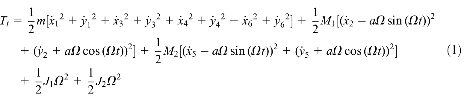
where M and m present the equivalent masses including the disks and the shafts, respectively; a is the eccentricity of disks; Ω is the rotational speed; xi, y i (i = 1, 2, …, 6) are the position coordinates of the journals and the disks, respectively.
The potential energy can be expressed as

where k11 and k22 are the stiffness coefficients of rotor_1 in the two orthogonal directions of the stationary coordinates, and k12 is the coupled stiffness. These parameters, involved in the anisotropic stiffness coefficients of rotor_1 and the rotational speed, are time-dependent in the stationary frame and derived in detail in Appendix 2.
Because the parallel misalignment exists between the two adjacent rotors, their displacements are coupled, that is, a constraint is embedded in the rotor system based on the theory of analytic dynamics. Hence, the constraint function can be defined as

where δ denotes the rotor misalignment, generally in the same order as the mass unbalance. The above constraint is holonomic and can be expressed in another form by introducing an angle variable as

where φ has a clear physical meaning, that it is the angle between the line of nodes 3 and 4, and the x-axis, shown in Figure 2. Then, the position coordinates x3, y3 can be replaced upon substituting the constraint equation (4) into equations (1) and (2). After considering the above holonomic constraint, the kinetic energy and the potential energy for the complete system can be written as follows

and

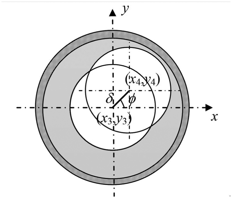
Schematic diagram of the motion relationship between the adjacent rotors with the parallel misalignment.
Generally, the oil film forces

The generalized force vector that comprised nonlinear oil film forces on the journal bearings is denoted by

where the nonlinear bearing forces are derived in detail in Appendix 3.
With respect to the generalized coordinates

Based on Lagrange’s equation

The general equation of motion considered both the misalignment effect and the unsymmetrical shaft can be presented as

where

Nonlinear dynamic analysis
Analysis approach and system parameters
Equation (11) embedded with the holonomic constraint due to parallel misalignment δ is a non-autonomous system, which is of 11 DOFs with strongly nonlinearity. The nonlinear functions such as sinϕ and cosϕ are included in these equations, so it is cumbersome to obtain the analytical or approximate solution. In the following study, the variable-step Runge–Kutta scheme in MATLAB package is introduced to numerically predict the dynamic characteristics of the generator rotor system. In the simulations, the termination criterion is specified as the error tolerance of less than 10−6, and the time series data corresponding to the first 400 rotating cycles is deliberately excluded for finding the steady-state response. Moreover, it is assumed that the rotor_2 is exciter and its mass is smaller than that of rotor_1 (generator rotor). The main parameters are summarized in Table 1 based on a practical rotor-bearing system of the 200-MW turbo-generator.
Values of the systematic parameters.

Steady-state responses of unsymmetrical generator rotors with parallel misalignment
Modal analysis
To facilitate later discussion, the free vibration of the corresponding rotor system supported by the linearized oil film bearings is first investigated here. Note that in the modal analysis, the faults of misalignment and unbalance are not included in the linearized model, namely, a = δ = 0. Thus, x3 = x4, y3 = y4 can be obtained from equation (4). Then, the equation of motion can be reduced to the linearized expression as follows

where
Natural frequencies for the linear system.

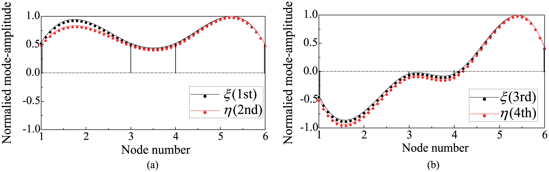
Mode shapes of the first four bending modes of the generator rotor system.
Nonlinear dynamic analysis
Below, the nonlinear dynamic behaviors of the unsymmetrical generator rotors with parallel misalignment are investigated by the bifurcation diagram, Poincaré maps, orbits, and its frequency spectrums. For clarity and demonstration purposes, some non-dimensional variables such as X = x/c, Y = y/c, A = a/c, and Δ = δ/c are introduced on the basis of the bearing clearance c.
The bifurcation diagram of the steady-state responses of the rotor system with the fault of misalignment is shown in Figure 4 (black dots), and the dynamic behaviors of the rotor system with the proper alignment are also investigated (red dots) to illustrate the effects of the misalignment and the oil film nonlinearity as a comparison. The results show that when Δ = 0.02, namely, the misalignment is equal to one-fiftieth of the bearing clearance, the qualitative behaviors of the responses are hardly effected by the small misalignment that the dynamic responses of journal center are synchronous at low speed Ω = 1200–2320 r/min. With the increase in the rotational speed Ω, the oil film instability 20 lead to some irregular oscillations of the rotor system and then the non-periodic bifurcation occurs. Note that the onset of the bifurcation can be slightly brought forward by the misalignment as compared to the aligned case. When the speed is at 2320 r/min, the rotor responses undergo a bifurcation again, resulting in a periodic motion. For the case of misalignment, however, the dynamic behaviors of the rotors will come back to a non-periodic motion at Ω = 2965 r/min.

Bifurcation diagrams of the steady-state responses in the horizontal direction with Ω = 1200–3000 r/min when ρ = 0.0549, A = 0.05, Δ = 0 (red dots), and Δ = 0.02 (black dots).
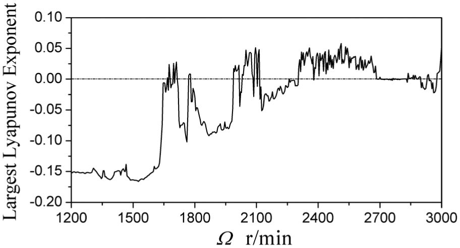
Figure 5 displays the largest Lyapunov exponent (LLE) diagram against the rotational speed Ω when Δ = 0.02, which can accurately identify the nonlinear dynamic behaviors of the systems. A negative value of the LLE denotes a stable periodic motion, a positive value can be an indication of chaotic oscillation, and the LLE tends to zero for the case of quasi-periodic motions.

Largest Lyapunov exponent diagram with Ω = 1200–3000 r/min when Δ = 0 (red line) and Δ = 0.02 (black line).
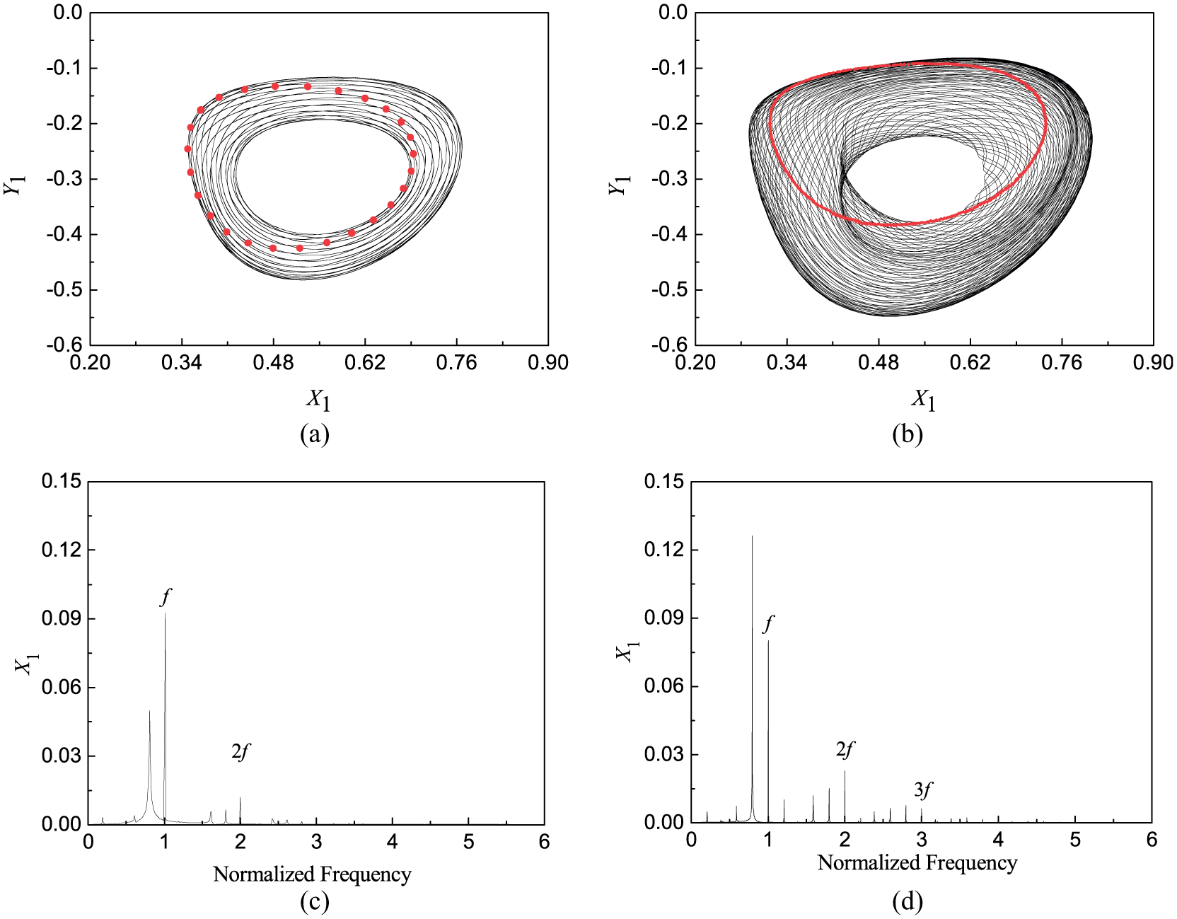
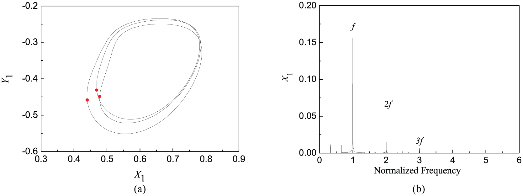
Figures 6–8 show the dynamic characteristics of the rotor system with a relatively small misalignment Δ = 0.02 for different speeds, which will be compared with aligned cases Δ = 0. It appears that the nonlinear phenomena become inconspicuous, and the linear characteristics are dominant near the third and fourth modes such as Ω = 1950 r/min that an isolated attractor marked by red dots in Poincaré map confirms that the response is periodic. In spectrum diagram, a frequency component of synchronous speed is dominant, but some super-harmonic components 2X and 3X are enhanced due to the effects of the misalignment fault.

The case when Ω = 1950 r/min: (a) and (b) are rotor orbits (black line) and Poincaré maps (red dots) with Δ = 0 and Δ = 0.02, respectively; (c) and (d) are spectrum diagrams with Δ = 0 and Δ = 0.02, respectively.
The case when Ω = 2500 r/min: (a) and (b) are rotor orbits (black line) and Poincaré maps (red dots) with Δ = 0 and Δ = 0.02, respectively; (c) and (d) are spectrum diagrams with Δ = 0 and Δ = 0.02, respectively.

The case when Ω = 2935 r/min: (a) and (b) are rotor orbits (black line) and Poincaré maps (red dots) with Δ = 0 and Δ = 0.02, respectively; (c) and (d) are spectrum diagrams with Δ = 0 and Δ = 0.02, respectively.
Figures 7(a) and (b) exhibit that the rotor orbits fluctuate within a relatively large range of vibration amplitude, and the ratios of harmonic frequencies are irrational in spectrum diagrams when Ω = 2500 r/min for both of two cases. A closed curve that consists of a large number of points presents in Poincaré map, all of which indicate that the effects of the tiny misalignment on dynamic responses of the rotor system are insignificant in the parameter.
When Ω = 2935 r/min in Figure 8, it can be seen that the tiny misalignment brings in a qualitative change in the rotor responses from the 3T-period into 6T-periodic motion, and some super-harmonic components emerge and dominate as compared with the aligned case in spectrum diagrams. Some of these signatures are coincident with the ones of the misaligned and unbalanced rotor-bearing system, which are often used to identify the onset of the fault in engineering.
Generally, the initial misalignment is tiny for a generator rotor, which may make little influences on oil film pressure distributing of hydrodynamic journal bearing. However, the fault may deteriorate to be a larger misalignment if the rotor system with the fault works in a long time of operation.
Figure 9 illustrates the dynamic behaviors of the system when Δ = 0.10, that is, the misalignment is one-tenth of the bearing clearance. The simulation results show that the steady-state responses of the system are still synchronous at low rotational speed, but a 3T-period window appear during the rotational speed 1640–2290 r/min in contrast to the tiny misalignment (see Figure 4), which implies chaos to be happened. From the LLE diagram shown in Figure 10, it is observed that the LLEs corresponding to the speed range Ω = 2290–2656 r/min are positive, that are chaos oscillations, but the values limit to zero in the speed range Ω = 2656–2907 r/min, which denote the rotor responses come back to the quasi-periodic motion. As Ω is further increased to Ω > 2907 r/min, the chaos oscillations occur again via a period-doubling bifurcation.

Bifurcation diagram of the steady-state response in the horizontal direction with the parameter Ω = 1200–3000 r/min when Δ = 0.10, ρ = 0.0549, and A = 0.05.
Largest Lyapunov exponent diagram with Ω = 1200–3000 r/min when Δ = 0.10.
Figure 11 presents the rotor responses when Ω = 1950 r/min. In contrast to the before case (see Figure 6), a typical 3T-period motion is induced from a periodic response that the rotor orbit is regular with three return points on Poincaré section, and some sub-harmonic and super-harmonic components exist in its frequency spectrum.
The case when Ω = 1950 r/min, Δ = 0.10: (a) rotor orbit and Poincaré map; (b) spectrum diagram.
From Figures 12 and 13, it can be observed that the quasi-periodic torus breaks and the period-doubling bifurcation cascades to chaos for a larger misalignment as compared with Figures 7 and 8. Then, the rotor orbits are irregular and the points on Poincaré section show the self-similarity with fine structure at rotational speeds Ω = 2500 and 2935 r/min. The spectrum diagram demonstrates the continuous frequency components with non-synchronous frequencies as well as their combinations, and that a sub-harmonic component is enhanced obviously, but the component from the unbalanced response is suppressed, which can be used to identify the misalignment fault and evaluate its extent.

The case when Ω = 2500 r/min, Δ = 0.10: (a) rotor orbit and Poincaré map; (b) spectrum diagram.

The case when Ω = 2935 r/min, Δ = 0.10: (a) rotor orbit and Poincaré map; (b) spectrum diagram.
Effect of misalignment on dynamic characteristics of rotor system
In this part, the effects of misalignment on the dynamics of rotor system are investigated by considering the parallel misalignment between the two rotors to be a bifurcation parameter.
Figure 14 reveals the bifurcation diagrams of the steady-state responses in the horizontal direction against the parallel misalignment Δ when Ω = 1843 and 2140 r/min, respectively. It can be seen that the motions of rotor system with tiny misalignment are stable. However, the increase in rotor misalignment can bring in some undesirable dynamic performances, such as jump phenomenon and chaotic oscillation. Furthermore, there exist plenty of period-doubling bifurcations within the range Δ = 0.26–0.35, 0.40–0.50 at Ω = 1843 r/min and Δ = 0.48–0.80 at Ω = 2140 r/min, respectively. It should be noted that a reverse period-doubling bifurcation is observed in Figure 14(a) and (b), in which the rotor responses of 14T-period for Δ = 0.40–0.44 go through the reverse period-doubling bifurcation to give a 7T-periodic response for Δ = 0.44–0.50 when Ω = 1843 r/min. The similar case also emerges for Δ = 0.6 when Ω = 2140 r/min.
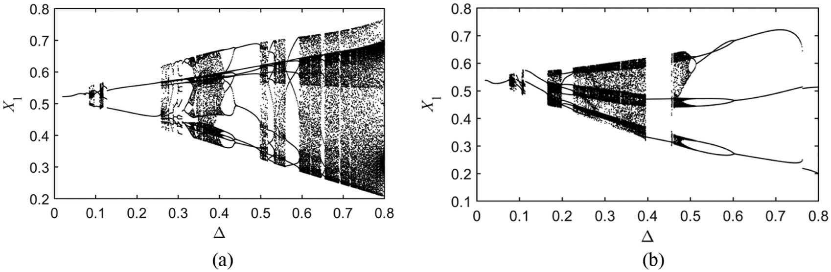
Bifurcation diagrams of the steady-state responses in the horizontal direction with the parameter Δ = 0.02–0.8 when ρ = 0.0549 and A = 0.05: (a) Ω = 1843 r/min and (b) Ω = 2140 r/min.
The misalignment can cause the changes of bearing distributing pressures, which may deteriorate the nonlinearity of journal bearing and lead to the differences of the oil film forces between bearings, and then influence the vibration amplitudes of rotor responses. In this article, the misalignment Δ is chosen as 0.00, 0.02, 0.10, and 0.20, respectively. Figure 15 illustrates the vibration amplitudes of steady-state response in the horizontal direction against the speed parameter Ω = 1200–3000 r/min, in which the rotational speed range can be split into three bands: 1200–1500, 1500–2400, and 2400–3000 r/min. The results show that the misalignments exert a slight influence on the response amplitudes of rotor system in the first band. As the speed Ω is increased from 1500 to 2400 r/min, however, an amplitude jump occurs due to the changes in the qualitative behaviors of the misaligned rotor system (see Figure 9). What is more, the large misalignment tends to bring forward the onset of the amplitude jump. When Ω = 2400–3000 r/min, the misalignments cause a prominent deviation in the response amplitude as compared with the aligned case (Δ = 0), especially for the higher speed such as Ω > 2800 r/min.
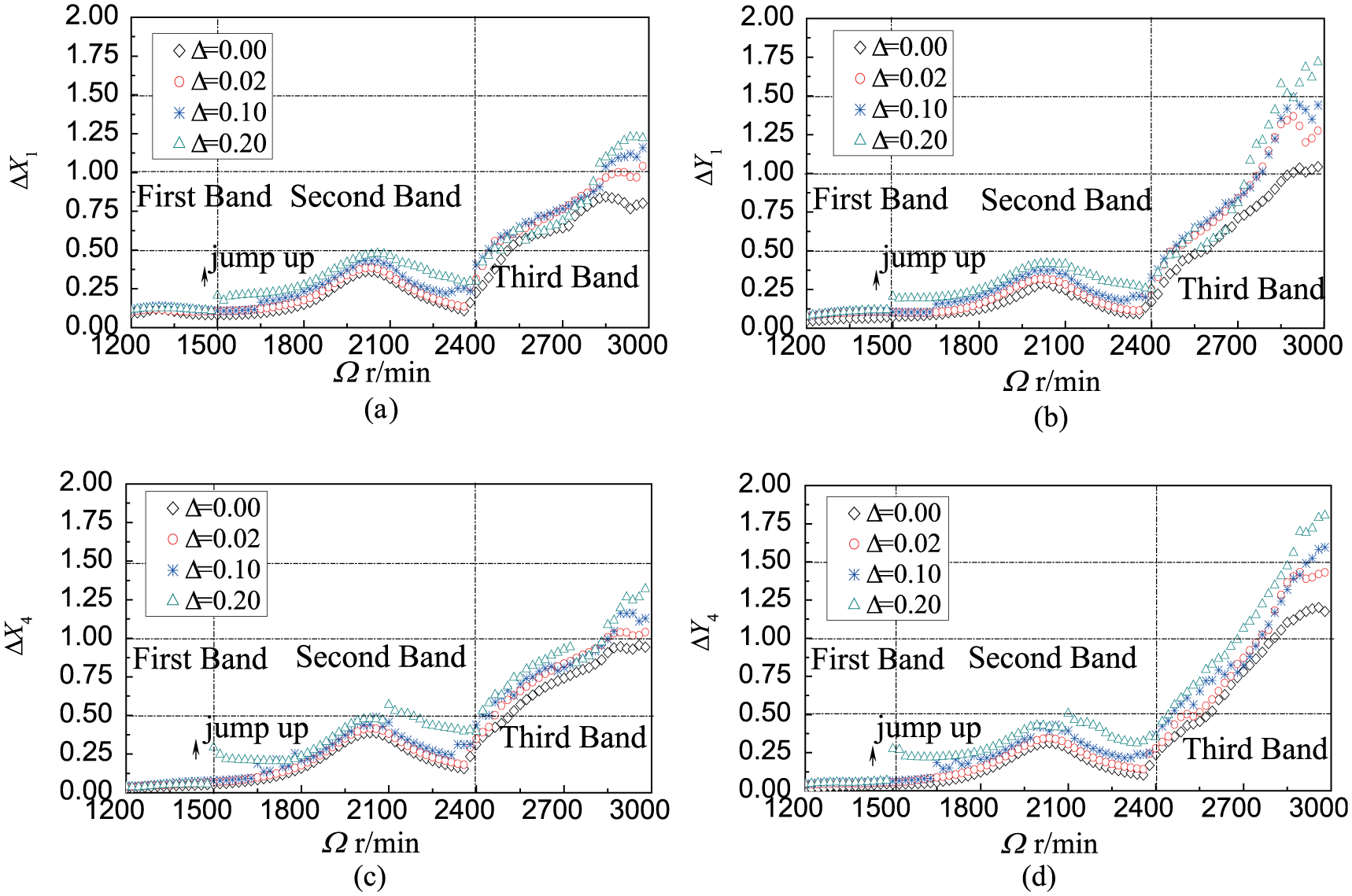
Vibration amplitudes of the steady-state responses with parameter Ω = 1200–3000 r/min, ρ = 0.0549, and A = 0.05 for different Δ.
Conclusion
The dynamic behaviors and vibration characteristics of an unsymmetrical rotor system with the misalignment fault are investigated in this work. The constraint described the parallel misalignment between two rotors is embedded into the dynamic model based on Lagrange’s equation. The nonlinear dynamic behaviors of the system are discussed by the graphical demonstration, such as the rotor orbits and its frequency spectra, Poincaré maps, and LLE. Some conclusions can be drawn as follows:
From the rotor-dynamics point of view, the super-synchronous component in the frequency spectra 2X is a typical characteristic in the diagnosis of rotor misalignment fault. Furthermore, the frequency component may increase with the misalignment and the rotational speed, even over the synchronous component 1X, which can be used to identify the misalignment fault and evaluate its extent.
From the nonlinear dynamics point of view, the misalignment may induce the change of rotor motion in the dynamic behaviors, such as the period-doubling bifurcation and the break of quasi-periodic torus, which may cause the chaotic motions of rotor system and the jump phenomena in response amplitudes.
Footnotes
Appendix 1
Appendix 2
Appendix 3
Handling Editor: Anand Thite
Declaration of conflicting interests
The author(s) declared no potential conflicts of interest with respect to the research, authorship, and/or publication of this article.
Funding
The author(s) disclosed receipt of the following financial support for the research, authorship, and/or publication of this article: The authors acknowledge the financial support from the National Natural Science Foundation of China through grants 11702213 and 11372245.