
Abstract
The calculation of friction power consumption and the performance of nano-magnetic fluids in sealed water turbines have proved to be hurdles in studies on nano-magnetic fluidic device designs and applications. In this article, we investigate the imbalanced rotation Ω ≠ 1/2 (rot υ) of a nano-magnetic fluid suspended in a paramagnetic carrier liquid. Through Langevin and Navier–Stokes equations, the formula for the theoretical friction power consumption can be calculated for the magnetic particles in the nano-magnetic fluid. The calculated value shows a well agreement with the test result. Further simulation indicates that the magnetic field gradient ΔBsum between the tooth space (wave trough) and the pole tooth (wave crest) has the most influence on the imbalanced rotation in a sealed nano-magnetic fluid device in a water turbine. Specifically, the larger the ΔBsum, the more obviously imbalanced the nano-magnetic fluid rotation will be at that location; and the imbalanced torque will be larger, so the seal differential pressure will be as well. As a result, the sealing capacity will be better and the frictional power consumption will be larger; and the reverse is also true. This study result can serve as a reference for designs for sealed nano-magnetic fluidic devices for water turbines, which is significant, especially given the heat from friction power consumption in the water turbine and its cooling equipment.
Introduction
As for the largest source of renewable energy in the world, hydropower is the most stable, efficient, and transportable energy form. 1 Worldwide, there are about 1.05 billion kilowatts of installed capacity yet to be developed.2–4 On the other hand, the main shaft sealing technology in water turbines has always been the technical bottleneck limiting hydroelectric devices. Classic sealing structures with regular materials5,6 often lead to “nonprogrammed halts” and serious environmental pollution. The Nanjingdu hydropower station experienced main shaft leakage 28 times from 1991 to 2005. The 1–3 units at the OzaAkko hydropower station has had serious leakage on multiple occasions. Similar problems have appeared in Tugur, Russia, the Gulf of Cambay in India, Three Gorges in China, Liujiaxia Gorges, Bapanxia Gorges, and the Ertan hydropower station many times, as well. The water leakage at hydropower stations including Baishiyao, Feilaixia, Hekou, and Honghua has caused a mix of oil and water, which extensively contaminated water resources.
Currently, solving the problem of leaking seals in the main shaft of a water turbine using nano-magnetic fluids has become a hot topic in the international hydropower industry. Nano-magnetic fluids, a liquid material with important value in industrial applications, have been applied widely in areas such as astronavigation, computers, vacuum seals, printing, dampers, and speakers. 7 Researchers have pursued many studies on nano-magnetic fluids.8,9 In particular, they have achieved success in the manufacture and production of nano-magnetic fluids. Wei et al. 10 and Hu 11 applied chemical precipitation methods to produce nano-magnetic fluids of a 50 nm particle size for Fe3O4. Kanno et al. 12 produced a vacuum-sealed nano-magnetic fluid with a saturation magnetization of 35.0 emu/g. The research shows that the performance and stability of nano-magnetic fluids are greatly affected by the size and distribution of the nano-magnetic particles.13,14 In recent years, many studies on the characteristics of nanofluids15–17 have greatly benefited the manufacture and production of nano-magnetic fluids.
As nano-magnetic fluid seals have been increasingly and widely applied, there have been more in-depth studies on the laws and dynamic characteristics affecting operations with nano-magnetic fluids. Hayat et al. 18 considered the Soret and Dufour effects when studying the hydrodynamics of nano-magnetic fluids. Through structure-level numerical solutions for homotopy, they found that under different physical parameters, the increase in the Casson number β and Hartman number Ha will cause a decrease in the speed f′(η). Hayat et al. 19 analyzed the influence of radiation on the flow of nano-magnetohydrodynamics induced by an extension-type surface. Ahmad and Asghar 20 analyzed how the boundary layer of the second-grade fluid flows when the surface stretches out and draws back at any speed. Hassani et al. 21 studied the analytical solutions for the boundary layer flow when a nanofluid flows past an extension-type surface. Zou 22 studied the centrifugal force of nano-magnetic fluids. Chi 23 studied the non-Newtonian flow characteristics of nano-magnetic fluids and achieved some breakthroughs on the bearing capacity of nano-magnetic fluids. Hu 24 studied the stability and fluidity of nano-magnetic fluid particles. Nemala et al. 16 studied the impact of temperature on nano-magnetic fluidic dynamics. These achievements have laid a good foundation for a theoretical system for nano-magnetic fluidics.
The application of nano-magnetic fluids in a water turbine seal is a brand-new technology, in which the tribological properties greatly affect the sealing stability. The friction torque caused by the imbalanced rotation of the nano-magnetic fluid is the issue of most concern in this area. Wang et al. 25 studied the tribological properties when adding a Mn-Zn ferrite magnetic nano-particle fluid. Yang 26 studied the friction power consumption and kinetic characteristics of nano-magnetic fluids. Wang et al. 27 studied seven factors that affect the bearing capacity of the magnetic fluid seal under the water environment in the main shaft seal of a turbine and verified the theoretical results through the experiments. Some important results and conclusions were obtained. Yang 28 made reasonable material selection and size design for the magnetic fluid seal structure of the main shaft in a turbine and optimized some important parameters of the magnetic circuit. Additionally, a series of design measures to improve the performance of the magnetic fluid seal were obtained. Yu and Zhang 29 used oil-based Fe3O4 as the sealing material and chose Nd2Fe14B permanent magnet material to provide external magnetic field. They simulated by ANSYS electromagnetic field analysis software. Numerical results showed that the seal ability is the worst and the failure is the most vulnerable in the places close to the shaft in the axial seal and the magnetic conductor side in the radial seal. The tooth shape, seal gap and other structural parameters have obvious influences on the sealing performance, which is stronger in a certain range of values of tooth and gap. Radionov et al. 30 carried out the simulation of the interconnected non-linear magnetic and hydrodynamic processes in the magnetic-fluid seal for rotational shaft. Both Chinese and international studies have shown good results. However, there is a bottleneck that currently exists in the theoretical calculation and experimental methods for friction power consumption, which is caused by the imbalanced rotation in the nano-magnetic fluidic seals and has hindered the development of nano-magnetic fluidic seal technology for water turbines.
In the study, first, the formula of the theoretical friction power consumption was derived for the magnetic particles in the nano-magnetic fluid. Then, the performance of nano-magnetic fluid sealing in a water turbine was simulated, which includes four parts. The first part is the introduction of sealing structure; the second is the introduction of numerical grid and schemes; the third part is the distribution of magnetic line of force, and the last part is the distribution of magnetic field strength and friction torque in the seal. Finally, model tests were carried out to validate the results obtained from theoretical analysis and numerical simulation. Based on the fact that the fluid viscosity increases as the magnetic field strength is enhanced, the comprehensive wear value of Mn-Zn ferrite magnetic-particle lubricating oil was increased, with the maximum being 1.43 times of the base liquid. This study has made breakthroughs in the theory of frictional power loss of magnetic fluid particles and the friction power consumption characteristics of magnetic field gradients and unbalanced rotations of the water turbine nano-magnetic fluid sealing device.
Mathematical derivation of friction power consumption caused by the imbalanced rotation of magnetic particles
Laws of motion for imbalanced rotations
Nano-magnetic fluid particles have magnetic dipole moments when rotating around an axis. Without an external magnetic field, the suspended particles are distributed randomly. In the sealing device for the main shaft in a water turbine, the motion of the nano-magnetic fluid can be indicated by Figure 1(a). When an external magnetic field is exerted, the angles for the dipole moments of these nano-magnetic particles will change, as indicated in Figure 1(b). The nanoparticles show paramagnetism, and the magnetization intensity can be calculated by the Langevin equation

Nano-magnetic fluid shear flow: (a) non-magnetic carrier liquid nanofluid flow and (b) external magnetic field nano-magnetic fluid flow.
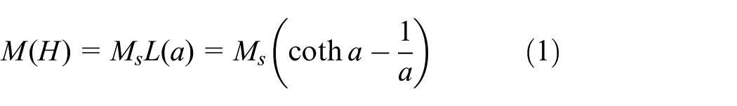
Nano-magnetic fluidic superparamagnetism fits the basic theories of paramagnetic materials. The Langevin function L(ξ) can be used to describe its magnetization characteristics

where a is Langevin’s parameter (magnetic-thermo ratio); n is the number of magnetic particles within the unit volume (m3); m is the magnetic moment of the particles (A m2); and ξ = μ0mH/(K0T), where μ0 is the magnetic conductivity in a vacuum, k is the Boltzmann constant, T is the absolute temperature (K), and H is the magnetic field intensity (T).
According to Newton’s internal friction model, a nano-magnetic fluid has a viscosity-temperature characteristic, just like an ordinary liquid. The imbalanced rotation of a nano-magnetic fluid Ω ≠ 1/2 (rot υ) will cause the friction torque. The nano-magnetic fluid motion of the rotational axial nano-magnetic fluidic sealing device can be described in Figure 1(a). This flow field can be indicated as

where υ0 is the rotational speed of the main shaft (m/s), z is the coordinate of the z-axis, L is the distance between the rotational axis surface and the magnetic pole (m), and
For a nano-magnetic fluid Ω ≠ 1/2 (rot υ), the rotation is considered to be

Mathematical formula derivation for the friction power consumption of magnetic particles
When the external magnetic field as shown in Figure 1(b) is applied, a displacement M is generated in the Z direction, which is smaller than that in the X direction. This feature is shown as

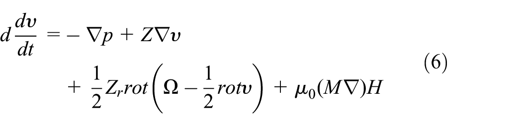


where d is the nano-magnetic fluid density (kg/m3), Z is the shear coefficient of viscosity, Zr is the rotation coefficient of viscosity, f is the relaxation time of magnetization intensity, and θ is the average value of rotational inertia.
Influenced by the magnetic field, and considering the static Maxwell equation and Navier–Stokes equation, the total viscosity of the nano-magnetic fluid in the rotational axis of the water turbine Zeff is


Thus, compared with Zr, ΔZ can express rotational viscosity more conveniently.
When considering the influence of rotation viscosity, considering equations (5)–(9), the formula can be expressed as
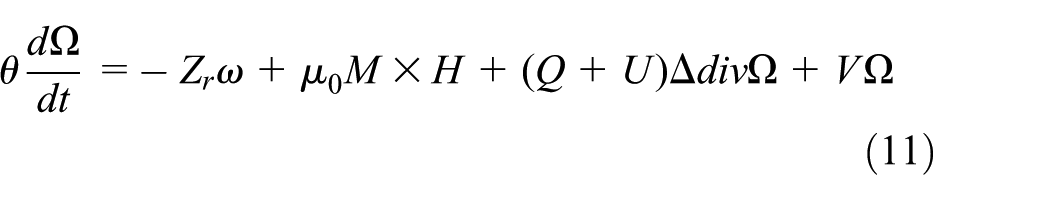
where Q, U, and V are the non-single uncertain rotation diffusion coefficients caused by rotation,
H 0 is the magnetic field intensity asserted on the nano-magnetic fluid. H is the magnetic field intensity inside the fluid. Here, considering the demagnetization coefficient of the container, M (H) can be derived from equation (1).
The friction torque caused by the external magnetic field asserted on the nano-magnetic fluid is

where V is the total volume of the nano-magnetic fluid (m3). After exerting the external magnetic field, a magnetic particle friction torque was added; when a new stable state was reached, the output torque of the dragging generator increased by ΔT. To calculate this better, a function K (H) has been introduced

then

Take e (H) in the equation and get the increment for the friction torque

From this equation, we can further calculate the friction power consumption.
Simulation calculation of the nano-magnetic fluid sealing performance
Affected by the external magnetic field, and considering the imbalanced rotation Ω ≠ 1/2 (rot υ), the total viscosity of the nano-magnetic fluid rotation and the friction torque asserted on the nano-magnetic fluid are two main factors influencing the sealing capacity of the water-turbine sealing device. However, the relationship between the magnetic field and the nano-magnetic fluid friction power consumption is complicated and non-linear, so we cannot draw accurate, quantitative conclusions from the mathematical models. ANSYS software is an efficient way to find the non-linear performance of the nano-magnetic fluid seal.
Nano-magnetic fluid sealing structure of the water turbine
The object of study is a typical low head water turbine on the Yellow River. It has a water-sealing diameter of 0.052 m for the main shaft in the water turbine model. The wheel diameter is 0.34 m. The water head is 5 m. The rotational speed is 68.18 r/min. According to ρgH = (1/2(ρν2) + D/ϒ), the sealing pressure difference Δp < 0.5 MPa. The structural design is indicated in Figure 2. The rotational units include the wheel, the water turbine main shaft, and the rotor. The static units are composed of the inner wall of the flow pass. The water flows between the rotating units and the static units. The nanofluid sealing device is installed between the main shaft and the wheels so as to create a seal between the dynamic and static units.

Sealing structure and device model for the main shaft in the water turbine.
Design the sealing device for the water turbine main shaft into one model with both ends face seal and radial seal. The magnetic pole is in tooth form and designed into a counter gear structure so as to increase the magnetic concentration. The magnetic pole is 2 mm in width and the distance between the tooth spaces is 1.5 mm. The magnetic pole is 2 mm in height and the sealing clearance is 0.3 mm.
In this article, Fe3O4 is selected as the nano-magnetofluid particles, which is processed into nanoscale particles by coprecipitation method, and the saturation magnetization is 0.04 T. The relative permeability of the nano-magnetic fluid is MURX of 1. The base liquid is oil, and its physical parameters are shown in Table 1. The permanent magnetic material is neodymium iron boron (NdFeB). An SA1010 model (#10 grade carbon steel) is selected for the pole piece to obtain a better linear distribution of the magnetic field, which acts as a magnetically permeable magnetic circuit in a magnetic liquid seal. The material for the main shaft is #45 grade steel.
The physical properties of the base fluid.

Model and calculation analysis
Based on ANSYS APDL, SOLID97 unit was selected to establish the model of the water turbine magnetic fluid sealing device. Then, the mesh was divided and finally loaded and run Main menu > Solution > Solve. During the simulation, the parameters and condition settings are as follows: the relative permeability is MURX 1.0; the coercive force MGXX and MGZZ are 0.975000 and 0 A/m, respectively. Because of the irregular clearance of the bearing, it is necessary to mesh with the smart dividing tool, the magnetic fluid and the shaft must be encrypted. The sealing device model was divided into grids as shown in Figure 3. In order to analyze the friction power consumption caused by the imbalanced rotation of the nano-magnetic fluid at different positions in the sealing clearance, three path curves were defined in the sealing clearance of the device, as indicated in Figure 4. The positions are A, B, and C. A total of 10 calculation points are set for each path curve. 31

Sealing device divided into grids for the nano-magnetic fluid in the water turbine main shaft.

Calculation points of positions A, B, and C.
In the nano-magnetic fluid sealing device, magnetic induction is different at different positions. The imbalanced rotation of the nano-magnetic fluid will show different migrations caused by the dipole moment m. As shown in Figure 5, at the sealing clearance of the device, the magnetic lines of force are concentrated and there is little magnetic flux leakage around it. Hence, under the influence of the magnetic field, the nano-magnetic fluid gathers at the pole tooth. If the magnetic field distribution is different at the sealing clearance, the sealing capacity will be different at various positions. As illustrated in Figure 6, the path curves in positions A, B, and C show similar trends in the structure. Different positions will see different friction power consumptions caused by different magnetic field distributions and imbalanced rotations of the nano-magnetic fluid. The wave crest is the magnetic strength on the internal path curve of the sealing clearance indicating the location of the tooth pole; the wave trough is the magnetic strength on the internal path curve of the sealing clearance indicating the location of the tooth space. Since B and C are tooth space on the left and right pole pieces of the same permanent magnet and are symmetrically distributed, the magnetic field, the friction torque, and the power loss are almost the same. The difference between the wave crest and wave trough is the magnetic field gradient ΔBsum. In the A position, there are 10 monitoring points. With the different structure, the magnetic flux density has a similar change, showing a periodic change, in which the maximum value of the magnetic flux density is 1.18 T, and the minimum value is 0.08 T. The variation of the magnetic fluid torque is consistent with the magnetic flux density in Figure 6(a). The maximum value is 2.5 × 10⁻⁵ N m and the minimum value is 0.3 × 10⁻⁵ N m. Positions B and C have the same conclusion with position A. The larger the ΔBsum, the more obvious the nano-magnetic fluid imbalanced rotation will be at that location; the unbalanced torque will be larger, and so will the seal differential pressure; as a result, the sealing capacity will be better, and the reverse is also true. This variation trend fits the friction torque formula for the nano-magnetic fluid increments.
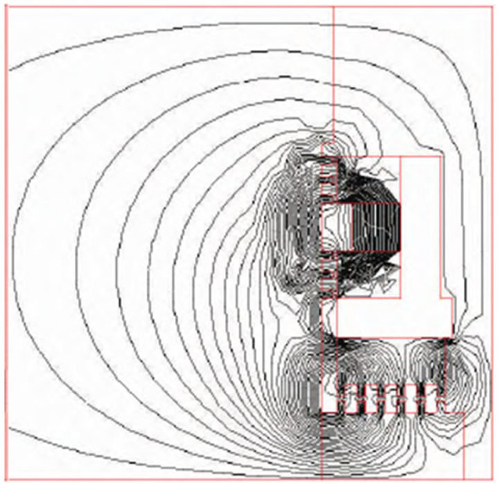
Magnetic lines of distribution of force for the sealing device.

Magnetic field distribution and nano-magnetic fluid particle torque changes at various positions in the sealing clearance: (a) position A, (b) position B, and (c) position C.
Test model
The friction power consumption caused by the imbalanced rotation of the nano-magnetic fluid sealing device can be broken down into two parts: the first part is the Newton internal friction power consumption of the carrier liquid; the second part is the desynchrony between the ferromagnetic particles and the carrier liquid under the impact of the external magnetic field. In order to obtain the friction power consumption mentioned in the second part, the device shown in Figure 7 was applied in the test. The test was carried out in the T4 test stand for hydraulic machinery in the hydropower test room at the Sifang Company’s research and test center shown in Figure 7(a); the model and actual size ratio was 21:1. Based on the schematic design in Picture B, there is nano-magnetic fluid inside the model water-turbine main shaft sealing device. The water turbine makes the main shaft rotate. Without an external magnetic field, the motion of the nano-magnetic fluid and the main shaft is synchronized. At that time,

Rotation friction system for the water turbine nano-magnetic fluid sealing device: (a) model test platform and (b) test schematic diagram.
The positions chosen for the test are close to those in the simulation calculation. As shown in Figure 8, according to the three path curves defined in the simulation calculation, the friction power consumption caused by the nano-magnetic fluid imbalanced rotation at three positions, A, B and C, was analyzed. The wave crest and trough appeared, respectively, at the tooth pole and the tooth space. The curve variation trend was the same as the magnetic field distribution and the nano-magnetic fluid particle torque. In Figure 8, the wave crest shows the power loss at the position of the tooth pole of the sealing clearance, and the wave trough shows the power loss at the position of the corresponding tooth space. The difference between the wave crest and wave trough is the power loss gradient. The friction power changes with ΔBsum, the larger the ΔBsum, the sealing capacity will be better and the friction power consumption will be larger; and the reverse is also true. From the perspective of the test, the calculation formula for the nano-magnetic fluid friction torque is verified.

Friction power consumption fluctuation curves for the sealed nano-magnetic fluid device.
Conclusion
In the nano-magnetic fluid seal in the water turbine, the imbalanced rotation Ω ≠ 1/2 (rot υ) of the nano-magnetic fluid will lead to rotational friction of the magnetic particles, with a magnetic dipole moment of m, suspended in the paramagnetic carrier liquid. The magnetic particles, originally oriented in the magnetic domain, change its direction due to the impact from the external magnetic field. The rotational friction torque formula of the magnetic particles derived from the Langevin and Navier–Stokes equations can be used to calculate the friction power consumption of the magnetic particles in the nano-magnetic fluid. The calculation result of the friction power consumption through the friction torque formula matches the simulation calculation and the test result. Further studies show that in a sealed nano-magnetic fluid device in the water turbine, the magnetic field gradient ΔBsum between the tooth space (wave trough) and the pole tooth (wave crest) has the most influence on imbalanced rotation. To be more specific, the larger the ΔBsum, the more obvious the nano-magnetic fluid imbalanced rotation will be at that location; and the unbalanced torque will be larger, and so will the seal differential pressure; as a result, the sealing capacity will be better and the friction power consumption will be larger; and the reverse is also true. The study results can be referred to when designing sealed nano-magnetic fluidic devices. Specifically, under certain friction power consumptions, a cooling device may be needed for the device.
Footnotes
Handling Editor: Farzad Ebrahimi
Declaration of conflicting interests
The author(s) declared no potential conflicts of interest with respect to the research, authorship, and/or publication of this article.
Funding
The author(s) disclosed receipt of the following financial support for the research, authorship, and/or publication of this article: This work was supported by Open Fund of Key Laboratory of Fluid and Power Machinery (Xihua University), Ministry of Education Sichuan (Grant No. szjj-2017-089 and Grant No. szjj-2017-100-1-001), Sichuan Science and Technology Department (No. 17CZ0034), and Xihua University Natural Fund (Z1510416).